A69GPRS01PV GPRS Data Logger
Shanghai Taoke Network Technology CO.,LTD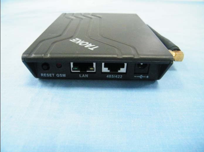
Click to zoom
Application Details
- Equipment Class
- JBP - Part 15 Class B Computing Device Peripheral
- Date of Grant
- Mar 06, 2012
- Application Purpose
- Original Equipment
- Date of Application
- Mar 05, 2012
- Equipment Note
- PV GPRS Data Logger
- Country
- China
Documents & Files
Document Text
Text extracted from the exhibit documents filed with the FCC. Open a document above to read the original.
Users Manual
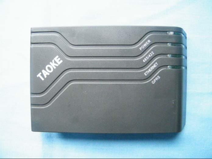
1 2 PV GPRS DATA LOGGER TK-G10-01/08/16/08S/16S Instruction 1. General TAOKE GPRS data logger of PV plants collects the operation data, including inverter, radiation, meter data, etc. by RS-485/422, and sends these data to w ebsite via GPRS and ether net so that user can check the power station runni ng status by logging on to internet website. 2.Scope of supply This logger will be delivered with the following components: 1. TK-G10 PV GPRS data logger 2. Power adapter 220VAC input ,12VDC /1A output 3. Manual 4. CD disk 5. Wall plug and screw 3. Technical data Product parameters Tech-Specifications Power supply 220V AC /12V DC Static power consumption < 2W Active power consumption < 8W Indication for status 4(top)+3(rear) LEDs Internet Connection GPRS+Ethernet Support frequency band GSM900/1800/850/1900 Ethernet connection 10BASE-T/100BASE-TX Ethernet interface RJ45-CAT5 PV device(inverter et c.) connection RS485/422 RS485/422 baudrate 1200 ~ 38.4K bps RS485/422 cable length Maxim 1000m RS485/422 interface RJ45 Data collection interval 5~30min(optional) Operation temperature -10 ~ 55 °C (14 ~ 131 °F ) Protection type IP21(In-door use only) Installation Desktop or Wall-mounting L × W × H 135 × 85 × 25mm Configuration Via computer 4.Ordering information TK-G10 - ×× × Sending data via ethernet to intranet server added Max. number PV devices(inverters,meters,etc.) Sending data via GPRS and ethernet to internet server 3 4 5.I/O illustration : DC power socket 485/422: RS-485/422 socket LAN: Ethernet socket GSM: GSM indicator RESET: Key for reset to “IP address allocated via DHCP automatically” 6. Installation Field connection diagram PV GPRS data logger should be installed where dry and ventilation are required in-door. It can be installed by desktop or wall-mounting. Please check t he GSM signal by GSM mobile before installation. DO NOT install inside metal box or near by big metal material. Adjust and fasten the logger antenna with hand. NOTE: DO NOT use spanner etc. tool to overdrive the antenna. Connection the logger via “RS485/ 422” socket to the PV devices, including inverter, meter, sensor (r adiation, temperature etc ) etc., and wiring among each other with CAT5 cable. RS-422/485 foot pin and CAT5 wire correspondence of logger The logger can also deliver data via ethernet. The logger is set to identify network via DHCP automatically. Connection the logger via “LAN” socket to a network ro uter with network cable, the LED-ETHERNET flashes quickly. When the LED is steady on, the IP address is allocated. If the LE D flashes slowly after one minute, the IP address is not allocated aut omatically. You can set a fix IP address via computer. Read the “Logger set tool User Manual” and use the “Logger set tool.exe” in the disk. If you want to reset “IP address allocated via DHCP automatically”, pull out the DC plug, press the reset key and RJ45 Pinouts/ Color of wire RS422 RS485 1 NC NC 2 NC NC 3/white green R+ 4/Blue T+ 485+(A)5/White blue T- 485-(B) 6/Green R- 7/ Brown GND GND 8 GND GND 5 6 plug in at the same time. The 4 LEDs on top are flashing. When all the LEDs are steady on, release the key. NOTE: Each logger connected to a network has got its own IP address. This address can not be used twice and can not be allocated to another logger, computer, etc. appliance. When the ‘ETHERNET’ indicator is steady on, but there is no data on website or you can not search the logger via computer with “Logger set tool.exe”. If the logger is set a fix IP address, you have set a wrong IP address or the IP address is allocated twice. If the logger is allocated IP address via DHCP automatically, the IP address is allocated twice. 7.Led illustration POWER:steady on when power supply is normal. 485/422:Off,no data is collected. flash 150ms when collection. Steady on, all the data is collected correctly. 500ms On/500ms Off, some data can not be collected. ETHERNET:Off,cable not connected to a router or a computer. Steady on,the IP address is allocated. 500ms On/500ms Off: obtaining IP address automatically. 500ms On/2500ms Off: IP address can not be allocated. GPRS:Off, GPRS not linked. steady on, the GPRS is linked. 500ms On/500ms Off, linking GPRS. 100ms On/100ms Off 5 times, 600ms Off, no SIM card inner simlock or the lock get loose GSM: Off,GSM not work. 500ms On/2500ms Off, the network is linked. 500ms On/500ms Off, linking the network. LAN: The two LEDs Off, ethernet is no linked. The two LEDs blinking. ethernet is linked. NOTE: IF the LED of ‘GSM’ is al ways linking the network, which the LED flash 500ms on/500ms of f a few seconds,and reset.The signal strength of GSM is very w eak ro the SIM card is illegal. 8.SIM card PIN and APN IF there is SIM card PIN and APN, the PIN and APN should be set to the logger beforehand. Read the “Logger set tool User Manual” and use the “Logger set tool.exe” in the disk. Trouble shooting LED Symptom Description ‘GPRS’ is off after ‘GSM’ is linked The APN is not set or wrong. ‘POWER’ on ,then ‘485/422’ on ,then ‘ETHERNET ’ on, then ‘GPRS’ on, — such revolve,and ‘GSM’ is off. The PIN is not set beforehand or is set wrong. And the logger is locked, unless the PIN is set again. ‘POWER’ and ‘485/422’ on at the same time ‘ETHERNET ’ and ‘GPRS’ off, then ‘POWER’ and ‘485/422’ off at the same time ‘ETHERNET ’ and ‘GPRS’ on — such cycle,and ‘GSM’ is off . The PUK is locked. IF the PIN is set wrong 3 times, the PUK will be locked. You should contact SIMCARD seller. 7 8 9. Trouble shooting NOTE This equipment has been tested an d found to comply with the limits for a Class B digital device, pursuant to part 15 of the FCC Rules. These limits are designed to provide reasonable protection against harmful interference in a residential installation. This equipment generates, uses and can radiate radio frequency energy and, if not installed and used in accordance with the instructions, may cause harmf ul interference to radio communications. However, there is no guarantee that interferen…
Text truncated - open the document above for the full version.
Cover Letter(s)
Shanghai Taoke Network Co.,Ltd Federal Communications Commission Authorization and Evaluation Division Confidentiality Request regarding application for certification of FCC ID: A69GPRS01. Purs uant to Sections 0.457 and 0.459 of the Commission’s Rules, we hereby request confidential treatment of information accompanying this application as outlined below: Exhibit Type File Name Block Diagram Schematics Operational Description Parts List Tune Up Info TK-G10_ Block Diagram.pdf TK-G10_ Schematics.pdf TK-G10_ Operational Description.pdf TK-G10_ Parts List.pdf TK-G10_Tune Up Info.pdf (Note- If Internal Photos or the Users Manual are to be requested under Long-Term Confidentiality justification must be required per the FCC’s Confidentiality Policy.) The above materials contain trade secrets and proprietary information not customarily released to the public. The public disclosure of these materials may be harmful to the applicant and provide unjustified benefits to its competitors. The applicant understands that pursuant to Section 0.457 of the Rules, disclosure of this application and all accompanying documentation will not be made before the date of the Grant for this application. Sincerely, (Grantee Contact’s Signature) Jianzhou Lu
External Photos
Z3VGPRS01 External Photo
ID Label/Location Info
This device complies with part 15 of the FCC Rules. Operation is subject to the following two conditions: (1)This device may not cause harmful interference, and (2) this device must accept any interfe- rence received, including interferenc e that may cause undesired operation. 5cm 2.5cm
Internal Photos
A69A69 A69GPRS01 Internal Photo
Test Report
Report No.: RZA1108-1392EMC01R2 Page 1 of 23 TESTING No. L2264 Part 15B TEST REPORT Product Name PV GPRS Data Logger Model Name TK-G10-01,TK-G10-08,TK-G10-16,TK-G10-08S,TK-G10-16S FCC ID A69GPRS01 Client Shanghai Taoke Network Co.,Ltd TA Technology (Shanghai) Co., Ltd. TA Technology (Shanghai) Co., Ltd. Test Report Report No.: RZA1108-1392EMC01R2 Page 2 of 23 GENERAL SUMMARY Product Name PV GPRS Data Logger Model Name TK-G10-01,TK-G10-08,TK- G10-16,TK-G10-08S,TK-G 10-16S FCC ID A69GPRS01 Report No. RZA1108-1392EMC01R2 Client Shanghai Taoke Network Co.,Ltd Manufacturer Shanghai Taoke Network Co.,Ltd Reference Standard(s) FCC Code CFR47 Part15B (2010-12) Radio frequency device. ANSI C63.4 (2003) Methods of Measurement of Radio-Noise Emission from Low-Voltage Electrical and Electronic Equipment in the Range of 9 KHz to 40GHz. Conclusion Test results in Chapter 2 of this test report are below limits specified in the relevant standards. General Judgment : Pass (Stamp) Date of issue: December 12 th , 2011 Comment The test result only responds to the measured sample. Approved by Director Revised by EMC Manager Performed by EMC Engineer TA Technology (Shanghai) Co., Ltd. Test Report Report No.: RZA1108-1392EMC01R2 Page 3 of 23 TABLE OF CONTENT 1. General Information ..................................................................................................................... 4 1.1. Notes of the test report.........................................................................................................4 1.2. Testing laboratory .................................................................................................................4 1.3. Applicant Information ............................................................................................................5 1.4. Manufacturer Information ......................................................................................................5 1.5. Information of EUT................................................................................................................6 1.6. Test Date ..............................................................................................................................7 2. Test Information ........................................................................................................................... 8 2.1. Summary of test results ........................................................................................................8 2.2. Radiated Emission ................................................................................................................9 2.3. Conducted Emission...........................................................................................................16 3. Main Test Instruments ................................................................................................................ 20 ANNEX A: The EUT Appearance and Test Setup .......................................................................... 21 A.1 EUT Appearance .....................................................................................................................21 A.2 Test Setup ...............................................................................................................................22 TA Technology (Shanghai) Co., Ltd. Test Report Report No.: RZA1108-1392EMC01R2 Page 4 of 23 1. General Information 1.1. Notes of the test report TA Technology (Shanghai) Co., Ltd. guarantees the reliability of the data presented in this test report, which is the results of measurements and tests performed for the items under test on the date and under the conditions stated in this test report and is based on the knowledge and technical facilities available at TA Technology (Shanghai) Co., Ltd. at the time of execution of the test. TA Technology (Shanghai) Co., Ltd. is liable to the client for the maintenance by its personnel of the confidentiality of all information related to the items under test and the results of the test. This report only refers to the item that has undergone the test. This report standalone dose not constitute or imply by its own an approval of the product by the certification Bodies or competent Authorities. This report can not be used partially or in full for publicity and/or promotional purposes without previous written approval of TA Technology (Shanghai) Co., Ltd. and the Accreditation Bodies, if it applies. If the electrical report is inconsistent with the printed one, it should be subject to the latter. 1.2. Testing laboratory Company: TA Technology (Shanghai) Co., Ltd. Address: No.145, Jintang Rd, Tangzhen Industry Park, Pudong City: Shanghai Post code: 201201 Country: P. R. China Contact: Yang Weizhong Telephone: +86-021-50791141/2/3 Fax: +86-021-50791141/2/3-8000 Website: http://www.ta-shanghai.com E-mail: [email protected] TA Technology (Shanghai) Co., Ltd. Test Report Report No.: RZA1108-1392EMC01R2 Page 5 of 23 1.3. Applicant Information Company: Shanghai Taoke Network Co.,Ltd Address: Room 201, Building.2, No.215, Rd Yaohua, Dist.Pudong City: Shanghai Postal Code: / Country: P.R.China Contact: Lu Jianzhou Telephone: +86 013916398386 Fax: +86 21 60936519 1.4. Manufacturer Information Company: Shanghai Taoke Network Co.,Ltd Address: Room 201, Building.2, No.215, Rd Yaohua, Dist.Pudong City: Shanghai Postal Code: / Country: P.R.China Telephone: +86 013916398386 Fax: +86 21 60936519 TA Technology (Shanghai) Co., Ltd. Test Report Report No.: RZA1108-1392EMC01R2 Page 6 of 23 1.5. Information of EUT General information Name of EUT: PV GPRS Data Logger IMEI: / Hardware Version: DAU-SPS-ENT V0.02 Software Version: V1.00.ENT.002 Antenna Type: External Antenna TA Technology (Shanghai) Co., Ltd. Test Report Report No.: RZA1108-1392EMC01R2 Page 7 of 23 Auxiliary Equipment Details AE1: Charger Model: YH-S15AV1201000 Manufacture: Yuhang Electric Appliance Co.,Ltd. S/N: / AE1: Notebook Model: IBM T61…
Text truncated - open the document above for the full version.
Test Setup Photos
Z3VGPRS01 Test Setup Photo 1、 RE(Below 1GHz) 2、 RE(Above 1GHz) 3、 CE 4、 RSE
Contact Information
Applicant
LU JIANZHOU
Test Firm
TA Technology (Shanghai) Co., Ltd.Zhihui Liu
Technical Specifications
| # | Rule Parts | Frequency Range | Power Output |
|---|---|---|---|
| 1 | 15B | - | - |
Other Applications from Shanghai Taoke Network Technology CO.,LTD
A69ETHERNET01
Mar 06, 2012PV WEB Data Logger
Equipment Class
JBP - Part 15 Class B Computing Device Peripheral