A6LAT1595-13Front End Satcom Module with Integrated Antenna
AeroAntenna Technology, Inc.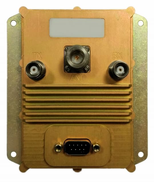
Click to zoom
Application Details
- Equipment Class
- TNB - Licensed Non-Broadcast Station Transmitter
- Date of Grant
- Nov 08, 2015
- Application Purpose
- Original Equipment
- Date of Application
- Nov 06, 2015
- Equipment Note
- Front End Satcom Module with Integrated Antenna
- Frequency Range
- 1626.50000000 - 1660.50000000
- Company
- AeroAntenna Technology, Inc.
- Country
- United States
Documents & Files
Document Text
Text extracted from the exhibit documents filed with the FCC. Open a document above to read the original.
Users Manual
20732 Lassen Street, Chatsworth, CA 91311 Phone: (818) 993-3842 Fax: (818) 993-4525 AT1595-13 BT1595-13 Active Inmarsat Aviation Antenna System User Manual AT15951384-01 Rev 1 BT1595-13 Bias Box/Amplifier AT1595-13 Antenna Industry Canada: This device complies with Industry Canada’s licence-exempt RSSs. Operation is subject to the following two conditions: (1) this device may not cause interference, and (2) this de- vice must accept any interference, including interference that may cause undesired oper- ation of the device. Industrie Canada: Le pressent appareil est conforme aux CNR d'Industrie Canada applicables aux appareils radio exempts de licence. L'exploitation est autorisese aux deux conditions suivantes: (1) l'appareil ne doit pas produire de brouillage, et (2) l'utilisateur de l'appareil doit accepter toutbrouillage radioeslectrique su-bi, meeme si le brouillage est susceptible d'en compro- mettre le fonctionnement. © 2013 AeroAntenna Technology, Inc. All Rights Reserved. AeroAntenna Technology, Inc. AT1595-13/BT1595-13 Aviation Antenna System Rev 122 Sep 2015 1Introduction & Installation The AT1595-13/BT1595-13 antenna system is designed to provide Internet connectivity for General Aviation and Business Aviation markets. The antenna system requires professional installation. 2Safety Information Regarding Exposure to RF Signals WARNING To satisfy FCC RF exposure requirements for mobiletransmitting devices, the minimum safety distance is 1.072 m (3.517 ft). This separation distance should be maintained between antenna and people during operation of the antenna. During normal operation, the radiation of the antenna is directed up towards the sky and only a person on the roof of the aircraft will be exposed to appreciable amounts of radiation. 3Cable Length Requirements To meet Inmarsat performance requirements and comply with FCC regulations, care must be taken to use the appropriate total RF cable length. Your antenna distributor should provide the appropriate cables. Cable Loss requirementRef. Cable/Length SDU* to Bias Box/Amplifier (TX)1.5 ± 0.2 dB @ 1650 MHz44 inches RG-316 SDU* to Bias Box/Amplifier (RX)1.5 ± 0.2 dB @ 1650 MHz44 inches RG-316 Bias Box/Amplifier to Antenna4.7 ± 0.2 dB @ 1650 MHz290 inches RG-142 * SDU = Satellite Data Unit 4Connection Diagram Bias Box/AmplifierAntenna SDU TX out RX in GPS in (NMEA) Airplane Power (28 VDC nominal) page 2 of 3© 2015 AeroAntenna Technology, Inc. All Rights Reserved. WARNING 1.072 METRES MICROWAVE RADIATION MINIMUM SAFE DISTANCE 5Specifications EQUIPMENT TYPE Mobile or Fixed Base Station INTEGRATED OPERATING ENVIRONMENT [ x ] Commercial [ x ] Light Industry & Heavy Industry POWER SUPPLY REQUIREMENT16 to 40V DC, 120W maximum RF INPUT POWER RATING (US & CANADA) 20 dBm or 0.1 Watt peak (conducted) EIRP21.6 dBW Max DUTY CYCLE N/A TX OPERATING FREQUENCY RANGE 1626.5 – 1660.5 MHz RX OPERATING FREQUENCY RANGE 1525.0 – 1559.0 MHz RF INPUT IMPEDANCE 50 Ohms MODULATION G1D, G1E, G1W EMISSION DESIGNATION1K69G1D, 1K69G1E, 1K69G1W ANTENNA TYPE Integral ANTENNA CONNECTOR TYPE Antenna: TNC (Female) Bias Box/Amplifier •ANT: Type N(Female) •TX: TNC(Female) •RX: TNC(Female) TEMPERATURE RATING STORAGE: OPERATIONAL: -55°C to +85°C -55°C to +70°C © 2011 AeroAntenna Technology, Inc. All Rights Reserved.page 3 of 3
Cover Letter(s)
Federal Communications Commission 7435 Oakland Mills Road Columbia MD 21046 Subject:Request for Confidentiality FCC ID:A6LAT1595-13 To Whom It May Concern: Pursuant to the provisions of Sections 0.457 and 0.459 of the Commission’s rules (47 CFR §§ 0.457, 0.459), we are requesting the Commission to withhold the following attachments as confidential document from public disclosure indefinitely. Schematic Diagram Block Diagram Theory of Operation Antenna Specification Above mentioned document contains detailed system and equipment description are considered as proprietary information in operation of the equipment. The public disclosure of above documents might be harmful to our company and would give competitor an unfair advantage in the market. In additional to above mentioned documents, pursuant to Public Notice DA 04-1705 of the Commission’s policy, in order to comply with the marketing regulations in 47 CFR §2.803 and the importation rules in 47 CFR §2.1204, while ensuring that business sensitive information remains confidential until the actual marketing of newly authorized devices. We are requesting the commission to grant short-term confidentiality request on the following attachments until 12/01/2015 External Photos Internal Photos Test Setup Photos User Manual It is our understanding that all measurement test reports, FCC ID label format and correspondent during certification review process cannot be granted as confidential documents and those information will be available for public review once the grant of equipment authorization is issued. Best Regards Alex Sissoev Sr. Electronics R&D Engineer AeroAntenna Technology, Inc. 09/10/2015
Cover Letter(s)
Date:09/10/2015 Federal Communications Commission Equipment Authorization branch 7435 Oakland Mills Road Columbia, MD 21046 To whom it may concern: I, the undersigned, hereby authorize UL Verification Services Inc. to act on our behalf in all manners relating to application for equipment authorization, including signing of all documents relating to these matters. Any and all acts carried out by UL Verification Services Inc. on our behalf shall have the same effect as acts of our own. I, the undersigned, hereby certify that we are not subject to a denial of federal benefits, that includes FCC benefits, pursuant to Section 5301 of the Anti-Drug Abuse Act of 1988, 21 U.S.C. 853(a). In authorizing UL Verification Services Inc. as our representative, we still recognize that we are responsible to: a)comply with the relevant provisions of the certification program; b)make all necessary arrangements for the conduct of the evaluation, including provision for examining documentation and access to all areas, records (including internal audit reports) and personnel for the purposes of evaluation (e.g. testing, inspection, assessment, surveillance, reassessment) and resolution of complaints; c)make claims regarding certification only in respect of the scope for which certification has been granted; d)do not use our product certification in such a manner as to bring the Certification Division into disrepute and not make any statement regarding our product certification which the Certification Division may consider misleading or unauthorized; e)upon suspension or cancellation of certification, discontinue use of all advertising matter that contains any reference thereto and return any certification documents as required by the Certification Division; f)use certification only to indicate the products are certified as being in conformity with specified standards; g)endeavor to ensure that no certificate or report nor any part thereof is used in a misleading manner; h)ensure that any reference to our product certification in communication media such as documents, brochures or advertising, complies with the requirements of the Certification Division; i)keep a record of all complaints made known to the us relating to the product’s compliance with requirements of the relevant standard and to make these records available to the when requested; j)take appropriate action with respect to such complaints and any deficiencies found in products or services that affect compliance with the requirements for certification; k)document the actions taken. This authorization is valid until further written notice from the applicant. Sincerely Yours, Alex Sissoev Sr. Electronics R&D Engineer AeroAntenna Technology, Inc. 09/10/2015
External Photos
Product and Board Pictures for AT1595-13 Antenna and BT1595-13 Bias Box mirror linemirror line 10 cm Page 2 of 6 AT1595-13 Antenna Page 3 of 6 mirror linemirror line 10 cm BT1595-13 Bias Box
Internal Photos
Product and Board Pictures for AT1595-13 Antenna and BT1595-13 Bias Box Page 4 of 6 10 cm mirror linemirror line AT15951314 Board (Antenna) Page 5 of 6 10 cm mirror linemirror line AT15951336 Board (Antenna) Page 6 of 6 mirror linemirror line 10 cm BT15951314 Board (Bias Box)
Parts List/Tune Up Info
September 10 th , 2015 Attn: To whom it may concern Re: Tune Up Procedure The AT1595-13/BT1595-13 does not require any tune up procedure because the amplifier/antenna are tested by an automatic test station. As part of the test, the Maximum RF output power value is measured. In case the RF output power is higher then specified in the acceptance test procedure, the AT1595-13/BT1595-13 will not pass and will receive a fail status. The AT1595-13/BT1595-13 features Automatic Gain Control mechanism, which keeps its gain constant under all electrical and environmental conditions. Sincerely, Alex Sissoev Sr. Electronics R&D Engineer AeroAntenna Technology, Inc. 20732 Lassen Str. Chatsworth CA, 91311 Tel: (818)993-3842 ext. 272 Fax: (818)993_4525 e-mail: [email protected]
RF Exposure Info
20732 Lassen Street, Chatsworth, CA 91311 Phone: (818) 993-3842 Fax: (818) 993-4525 RF Exposure Limits for AT1595-13 BT1595-13 Active Inmarsat Antenna Table of Contents 1 METHOD OF MEASUREMENTS.............................................................................................................................2 2 CALCULATION METHOD FOR RF SAFETY DISTANCE.................................................................................2 3 RF EVALUATION..........................................................................................................................................................2 The criteria used to evaluate the environmental impact of human exposure to radio frequency (RF) radiation is listed in FCC P.1.1310 & P.2.1091 1 METHOD OF MEASUREMENTS In order to demonstrate compliance with FCC P.2.1091, the following information is needed: ■Calculation that estimates the minimum separation distance (20 cm or more) between an antenna and persons required to satisfy power density limits for free space. ■Antenna installation and device operating instructions for installers (professional/unskilled users), and the parties responsible for ensuring compliance with the RF exposure requirement. ■Any caution statements and/or warning labels that are necessary in order to comply with the exposure limits. ■Any other RF exposure related issues that may affect compliance. 2 CALCULATION METHOD FOR RF SAFETY DISTANCE The power density, S, in units of mW/cm 2 is: S= P IN G 4πr 2 = EIRP 4πr 2 Where P IN is power input to the antenna in mW, G is the numeric (linear) gain of the antenna relative to isotropic radiator, EIRP is the equivalent isotropic radiated power, and r is the distance to center of radiation in cm. Therefore: r= √ EIRP 4πS 3 RF EVALUATION Antenna installation and device operating instructions shall be provided to installers to maintain and ensure compliance with RF exposure requirements. Caution statements and/or warning labels that are necessary in order to comply with the exposure limits will be indicated in the User's Manual and displayed on the device label. Using the maximum EIRP of 51.3 dBm and the power density of 1 mW/cm 2 for general population/uncontrolled exposure: page 2 of 3 r= √ 10 ( 51.6dBm 10 ) 4π mW cm 2 = √ 144,544mW 4π mW cm 2 =107.2cm The recommended minimum distance is 107.2 cm in free space. During normal operation, the radiation pattern is directed up towards the sky and only a person walking on the roof of the airplane would be exposed to appreciable levels of radiation. page 3 of 3
Test Report
Test Report In accordance with FCC Rules and Regulations, Volume II, Part 2 and to Part 87 Sub-part 2.1033 (c)(1): Name and Address of Applicant: AeroAntenna Technology, Inc. 20732 Lassen Str. Chatsworth, CA, USA 91311 Manufacturer: AeroAntenna Technology, Inc. Test Laboratory/Issuer:AeroAntenna Technology, Inc. Test Location: AeroAntenna Technology, Inc. Product Type:Geosynchronous Orbit Aeronautical Mobile Satellite Services Aircraft Earth Station Equipment Model Number:AT1595-13/BT1595-13 (c)(2) FCC ID:A6LAT1595-13 (c)(3) Instruction Manuals:See attached. (c)(4) Type of Emission:BPSK, QPSK, QAM (c)(5) Frequency Range:1626.5MHz – 1660.5MHz (c)(6) Power Rating:0.3 Watts (Variable) EIRP Rating:100 Watts (Variable) (c)(7) Maximum Allowed Power:60 Watts Maximum Allowed EIRP:2000 Watts (c)(8) Voltages and Currents in all RF Elements: Voltage = 28V ±12V Current (quiescent @28V) = 0.35A (c)(9) Tune-Up Procedure: See attached exhibits. (c)(10) Circuit Diagram and Description:Circuitry providing suppression of emissions and limiting output power (c)(11) Label Information:See attached exhibits. (c)(12) Photographs:See attached exhibits. (c)(13) Digital Modulation Description: N/A (c)(14) Test and Measurement Data:Follows. Engineer:Alex Sissoev Sr. Electronics R&D Engineer, AeroAntenna Technology, Inc. _____________________________ Date of Report:September 24 th 2015 Table of Contents Test Report.................................................................................................................................................1 Test Results Summary................................................................................................................................4 Carrier Output Power And Conducted Spurious Emissions......................................................................5 Test Procedure..................................................................................................................................5 BPSK 1626.5MHz Conducted Spurious Emissions .............................................................................6 BPSK 1643.5MHz Conducted Spurious Emissions .............................................................................8 BPSK 1660.5MHz Conducted Spurious Emissions............................................................................10 QPSK 1626.5MHz Conducted Spurious Emissions............................................................................12 QPSK 1643.5MHz Conducted Spurious Emissions............................................................................14 QPSK 1660.5MHz Conducted Spurious Emissions............................................................................16 QAM 1626.5MHz Conducted Spurious Emissions............................................................................18 QAM 1643.5MHz Conducted Spurious Emissions............................................................................20 QAM 1660.5MHz Conducted Spurious Emissions............................................................................22 Field Strength Of Radiated Spurious Emissions......................................................................................24 Test Procedure................................................................................................................................24 Test Steps........................................................................................................................................25 Maximum EIRP Level @1626.5MHz............................................................................................26 Maximum EIRP Level @1643.5MHz............................................................................................27 Maximum EIRP Level @1660.5MHz............................................................................................28 BPSK 1626.5MHz Radiated Spurious Emissions...............................................................................29 BPSK 1643.5MHz Radiated Spurious Emissions...............................................................................30 BPSK 1660.5MHz Radiated Spurious Emissions...............................................................................31 QPSK 1626.5MHz Radiated Spurious Emissions...............................................................................32 QPSK 1643.5MHz Radiated Spurious Emissions...............................................................................33 QPSK 1660.5MHz Radiated Spurious Emissions...............................................................................34 QAM 1626.5MHz Radiated Spurious Emissions................................................................................35 QAM 1643.5MHz Radiated Spurious Emissions................................................................................36 QAM 1660.5MHz Radiated Spurious Emissions................................................................................37 Occupied Bandwidth................................................................................................................................38 Test Procedure................................................................................................................................38 BPSK 151.2ksps @ 1626.5MHz Occupied Bandwidth......................................................................39 BPSK 151.2ksps @ 1643.5MHz Occupied Bandwidth......................................................................40 BPSK 151.2ksps @ 1660.5MHz Occupied Bandwidth......................................................................41 QPSK 151.2ksps @ 1626.5MHz Occupied Bandwidth......................................................................42 QPSK 151.2ksps @ 1643.5MHz Occupied Bandwidth......................................................................43 QPSK 151.2ksps @ 1660.5MHz Occupied Bandwidth......................................................................44 QAM 151…
Text truncated - open the document above for the full version.
Test Setup Photos
Appendix C Test Setup Photographs Illustration 74: Conducted Emissions Test Setup. Illustration 75: Radiated Emissions Test Setup. RF Signal Generator Source is located outside of the anechoic chamber on the EUT side. Illustration 76: Radiated Emissions Test Setup. Receiver (Spectrum Analyzer) is located outside of the anechoic chamber on the receiver Standard Gain Horn side. Illustration 77: Radiated Emissions Test Setup. Standard Gain Horn with adjustable polarization axis. Illustration 78: Radiated Emissions Test Setup. EUT mounted on a 2-axis turntable inside the anechoic chamber (front and back).
Contact Information
Applicant
Alex Sissoev(Senior Engineer)
Technical Specifications
| # | Rule Parts | Frequency Range | Power Output | Emission | Tolerance |
|---|---|---|---|---|---|
| 3 | 87 | 1.63 GHz - 1.66 GHz | 20.00 mW | 1K69D1W | 0.01 ppm |
Other Applications from AeroAntenna Technology, Inc.
A6LAT1621-20
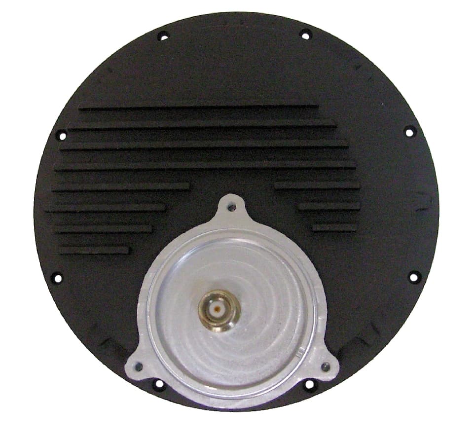
Jan 31, 2012ACTIVE IRIDIUM ANTENNA
Equipment Class
AMP - Amplifier