A6LAT1621-20ACTIVE IRIDIUM ANTENNA
AeroAntenna Technology, Inc.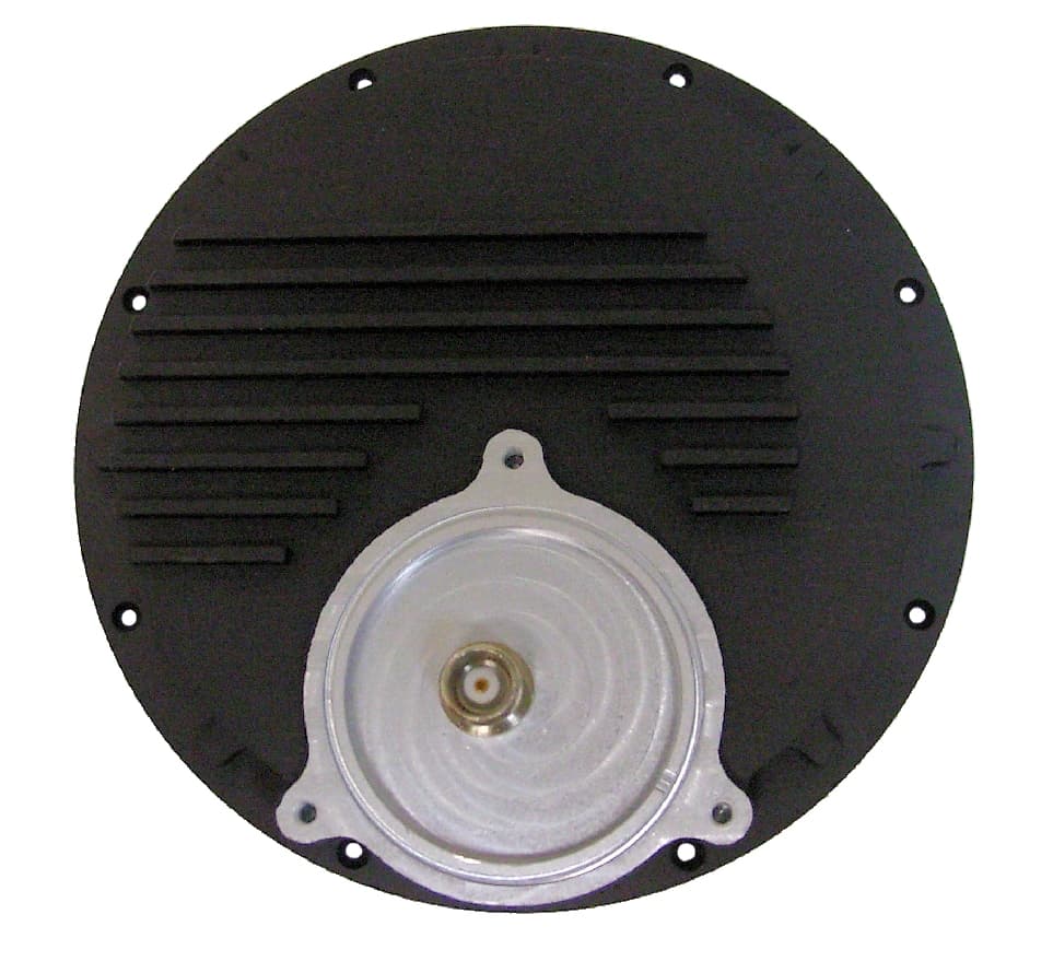
Click to zoom
Application Details
- Equipment Class
- AMP - Amplifier
- Date of Grant
- Jan 31, 2012
- Application Purpose
- Original Equipment
- Date of Application
- Jan 31, 2012
- Equipment Note
- ACTIVE IRIDIUM ANTENNA
- Frequency Range
- 1616.00000000 - 1626.50000000
- Company
- AeroAntenna Technology, Inc.
- Country
- United States
Documents & Files
Document Text
Text extracted from the exhibit documents filed with the FCC. Open a document above to read the original.
Users Manual
20732 Lassen Street, Chatsworth, CA 91311 Phone: (818) 993-3842 Fax: (818) 993-4525 AT1621-20 Active Iridium Antenna User Manual This device complies with Part 15 of the FCC Rules. Operation is subject to the following two conditions: (1) this device may not cause harmful interfer ence and (2) this device must accept any interference received, including in terference that may cause undesired operation. To satisfy FCC RF exposure require ments for mobile transmitting devices, the minimum safety distance is 55 cm (21.7 inches). This separation distance should be maintained between an tenna and people during operation of the antenna. © 2011 AeroAntenna Technology, Inc. All Rights Reserved. AeroAntenna Technology, Inc. AT1621-20 Active Iridium Antenna User Manual Rev 117 Jan 2011 Rev History RevChanges 1 •First version. • • Table of Contents 1Introduction...............................................................................................................................3 2Important Safety Information Regarding Exposure to RF Signals......................3 3Cable Length Requirements................................................................................................3 4Antenna Kit Contents.............................................................................................................4 5Connecting Your Antenna....................................................................................................4 5.1Outside/Above Decks....................................................................................................5 5.1.1Bring long RF cable to top of pole or mast...............................................5 5.1.2Feed cable through mounting bracket and attach TNC connector to antenna..........................................................................................................................5 5.1.3Screw in Mounting Screws to affix mounting bracket to antenna.6 5.1.4Place mounting bracket over pole and tighten set screws................6 5.2Inside/Below Decks.......................................................................................................7 5.2.1Attach Type N connector from long RF cable to bias box..................7 5.2.2Attach short RF cable to bias box and phone/docking station........8 5.2.3Connect DC power (9 to 36 VDC, 30W max) to bias box. ..................9 6Specifications..........................................................................................................................10 © 2012 AeroAntenna Technology, Inc. All Rights Reserved.page 2 of 10 AT1621-20 Active Iridium Antenna User Manual Rev 117 Jan 2011 1Introduction The AT1621-20 antenna is designed for Iridium applications where long RF cables are needed and a passive antenna cannot be used. The AT1621-20 has an integrated power amplifier (for transmitting signals to the satellite) and low noise amplifier (for receiving signals from the satellite) 2Important Safety Information Regarding Exposure to RF Signals WARNING To satisfy FCC RF exposure requirements for mobile transmitting devices, the minimum safety distance is 55 cm (21.7 inches). This separation distance should be maintained between antenna and people during operation of the antenna. 3Cable Length Requirements To meet Iridium performance requirements and comply with FCC regulations, care must be taken to use the appropriate total RF cable length. Your antenna distributor should provide the appropriate cable. Total Cable Loss Requirement 13.3 dB total for two cables Reference Cable Set 5 ft (1.5 m) RG58LL 1.1 dB loss @1621 MHz 115 ft (35 m) LMR240 12.2 dB loss @ 1621 MHz © 2012 AeroAntenna Technology, Inc. All Rights Reserved.page 3 of 10 WARNING MICROWAVE RADIATION MINIMUM SAFE DISTANCE 0.55 METRES AT1621-20 Active Iridium Antenna User Manual Rev 117 Jan 2011 4Antenna Kit Contents DC ANTPHONE WARNING MICROWAVE RADIATION MINIMUM SAFE DISTANCE 0.55 METRES 1 3 2 4 5 6 7 1.4 in (35.6 mm) 4 i n ( 1 0 1 . 6 m m ) 1.4 in ID MAX (35.6 mm) antenna bias box mounting bracket set screws (3) mounting screws (3) flat washers (3) split washers(3) 5Connecting Your Antenna WARNING To satisfy FCC RF exposure requirements for mobile transmitting devices, the minimum safety distance is 55 cm (21.7 inches). This separation distance should be maintained between antenna and people during operation of the antenna. © 2012 AeroAntenna Technology, Inc. All Rights Reserved.page 4 of 10 WARNING MICROWAVE RADIATION MINIMUM SAFE DISTANCE 0.55 METRES AT1621-20 Active Iridium Antenna User Manual Rev 11 Aug 2011 5.1Outside/Above Decks 5.1.1Bring long RF cable to top of pole or mast 5.1.2Feed cable through mounting bracket and attach TNC connector to antenna © 2011 AeroAntenna Technology, Inc. All Rights Reserved.page 5 of 10 TNC to bias box WARNING MICROWAVE RADIATION MINIMUM SAFE DISTANCE 0.55 METRES Type N antenna pipe/ mast mounting bracket to antenna TNC long RF cable pipe/ mast Type N to bias box AT1621-20 Active Iridium Antenna User Manual Rev 11 Aug 2011 5.1.3Screw in Mounting Screws to affix mounting bracket to antenna 5.1.4Place mounting bracket over pole and tighten set screws. © 2011 AeroAntenna Technology, Inc. All Rights Reserved.page 6 of 10 to bias box Type N WARNING MICROWAVE RADIATION MINIMUM SAFE DISTANCE 0.55 METRES antenna WARNING MICROWAVE RADIATION MINIMUM SAFE DISTANCE 0.55 METRES Type N to bias box antenna pipe/ mast mounting bracket AT1621-20 Active Iridium Antenna User Manual Rev 11 Aug 2011 5.2Inside/Below Decks 5.2.1Attach Type N connector from long RF cable to bias box. © 2011 AeroAntenna Technology, Inc. All Rights Reserved.page 7 of 10 Type N WARNING MICROWAVE RADIATION MINIMUM SAFE DISTANCE 0.55 METRES DC ANTPHONE bias box antenna AT1621-20 Active Iridium Antenna User Manual Rev 117 Jan 2011 5.2.2Attach short RF cable to bias box and phone/docking station. © 2012 AeroAntenna Technology, Inc. All Rights Reserved.page 8 of 10 WARNING MICROWAVE RADIATION MINI…
Text truncated - open the document above for the full version.
Cover Letter(s)
Federal Communications Commission Authorization and Evaluation Division Re: Confidentiality Request regarding application for certification of FCC ID: A6LAT1621-20. Pursuant to Sections 0.457 and 0.459 of the Commission’s Rules, we hereby request confidential treatment of information accompanying this application as outlined below: Permanent Confidential: Exhibit TypeFile Name Block DiagramAT1621-20_block_diagram_FCC.pdf SchematicsSchematic_Antenna.pdf SchematicsSchematic_Bias_Box.pdf Parts ListAntenna_Parts_List.pdf Parts ListBias_Box_Parts_List.pdf Tune Up InfoTimco no-tune-up-proc letter.pdf The above materials contain trade secrets and proprietary information not customarily released to the public. The public disclosure of these materials may be harmful to the applicant and provide unjustified benefits to its competitors. The applicant understands that pursuant to Section 0.457 of the Rules, disclosure of this application and all accompanying documentation will not be made before the date of the Grant for this application. Pursuant to DA04-1705 June 15, 2004 of the Commission’s public notice, we also request temporary confidential treatment of information accompanying this application as outlined below: Short term Confidential (45 days): Exhibit TypeFile Name External PhotosExternal Pictures.pdf Internal PhotosInternal Pictures.pdf User ManualUserManual_half_letter.pdf page 1 of 2 an AS9100 Certified Company 20732 Lassen Street, Chatsworth, CA 91311 Phone: (818) 993-3842 Fax: (818) 993-4525 Sincerely, William P Eaton, Ph.D. Senior Engineer AeroAntenna Technology, Inc. page 2 of 2
External Photos
TOP VIEWBOTTOM VIEW BIAS BOX SIDE VIEW BOTTOM VIEW ANTENNA BOTTOM VIEW TNCF connector TOP VIEW TNCF connector (to handset or docking station) N Type Female connector (to antenna) P602C Connector for DC voltage SIDE VIEW
ID Label/Location Info
Label Samples for AT1621-20 Active Iridium Antenna page 1 of 1 an AS9100 Certified Company 20732 Lassen Street, Chatsworth, CA 91311 Phone: (818) 993-3842 Fax: (818) 993-4525
Internal Photos
BIAS BOX ANTENNA
Operational Description
Operational Description AT1621-20 Active Iridium Antenna The AT1621-20 antenna is an active antenna that is an accessory for Iridium transceivers (handsets or modems). The Iridium satellite constellation is a large group of satellites providing voice and data coverage to satellite phones, pagers and integrated transceivers over Earth's entire surface. The AT1621-20 is designed for Iridium applications where long RF cables are needed and a passive antenna cannot be used. The AT1621-20 has an integrated power amplifier (for transmitting signals to the satellite) and low noise amplifier (for receiving signals from the satellite). page 1 of 1 an AS9100 Certified Company 20732 Lassen Street, Chatsworth, CA 91311 Phone: (818) 993-3842 Fax: (818) 993-4525
RF Exposure Info
AeroAntenna Technology, Inc. AS9100 Certified Company 20732 Lassen Street, Chatsworth, CA 91311 Phone: (818) 993-3842 Fax: (818) 993-4525 RF Exposure Limits for AT1621-20 Active Iridium Antenna Table of Contents 1 METHOD OF MEASUREMENTS.............................................................................................................................2 2 CALCULATION METHOD FOR RF SAFETY DISTANCE.................................................................................2 3 RF EVALUATION..........................................................................................................................................................2 The criteria used to evaluate the environmental impact of human exposure to radio frequency (RF) radiation is listed in FCC P.1.1310 & P.2.1091 1 METHOD OF MEASUREMENTS In order to demonstrate compliance with FCC P.2.1091, the following information is needed: ■Calculation that estimates the minimum separation distance (20 cm or more) between an antenna and persons required to satisfy power density limits for free space. ■Antenna installation and device operating instructions for installers (professional/unskilled users), and the parties responsible for ensuring compliance with the RF exposure requirement. ■Any caution statements and/or warning labels that are necessary in order to comply with the exposure limits. ■Any other RF exposure related issues that may affect compliance. 2 CALCULATION METHOD FOR RF SAFETY DISTANCE The power density, S, in units of mW/cm 2 is: S= P IN G 4πr 2 = EIRP 4πr 2 Where P IN is power input to the antenna in mW, G is the numeric (linear) gain of the antenna relative to isotropic radiator, EIRP is the equivalent isotropic radiated power, and r is the distance to center of radiation in cm. Therefore: r= √ EIRP 4πS 3 RF EVALUATION Antenna installation and device operating instructions shall be provided to installers to maintain and ensure compliance with RF exposure requirements. Caution statements and/or warning labels that are necessary in order to comply with the exposure limits will be indicated in the User's Manual and displayed on the device label. Using the maximum EIRP of 42.42 dBm and the power density of 1 mW/cm 2 for general population/uncontrolled exposure: page 2 of 3 r= √ 10 ( 42.42dBm 10 ) 4π mW cm 2 = √ 17458.2mW 4π mW cm 2 =37.3cm The recommended minimum distance is 37.3 cm. In practice, 55 cm is printed on the product because we use the same warning label from a higher power product. page 3 of 3
Test Report
AeroAntenna Technology, Inc. AS9100 Certified Company 20732 Lassen Street, Chatsworth, CA 91311 Phone: (818) 993-3842 Fax: (818) 993-4525 Test Report FCC Part 25 Testing for AT1621-20 Active Iridium Antenna FCC ID: A6LAT1621-20 Table of Contents 1 INTRODUCTION..........................................................................................................................................................4 1.1 SCOPE.................................................................................................................................................................4 1.2 RELATED SUBMITTALS/GRANTS...........................................................................................................4 1.3 NORMATIVE REFERENCES........................................................................................................................4 1.4 DATE OF TESTING.........................................................................................................................................4 2 PERFORMANCE ASSESSMENT..............................................................................................................................4 2.1 APPLICANT INFORMATION......................................................................................................................4 2.2 MANUFACTURER...........................................................................................................................................5 2.3 EQUIPMENT UNDER TEST (EUT)...........................................................................................................5 2.4 EUT TECHNICAL SPECIFICATION...........................................................................................................5 2.5 LIST OF EUT PORTS......................................................................................................................................5 2.6 LIST OF ACCESSORIES.................................................................................................................................6 2.7 LIST OF PERIPHERAL DEVICES USED FOR TESTING.....................................................................6 3 EUT OPERATING CONDITIONS AND CONFIGURATIONS DURING TESTS...........................................7 3.1 CLIMATE TEST CONDITIONS....................................................................................................................7 3.2 OPERATIONAL TEST CONDITIONS & ARRANGEMENT FOR TEST SIGNALS.........................7 4 TESTS FOR PART 25..................................................................................................................................................7 5 SUMMARY OF TEST RESULTS................................................................................................................................8 5.1 LOCATION OF TESTS....................................................................................................................................8 5.2 APPLICABILITY & SUMMARY OF EMC EMISSION TEST RESULTS............................................8 5.3 MODIFICATIONS TO EUT FOR COMPLIANCE PURPOSES.............................................................9 5.4 DEVIATION FROM STANDARD TEST PROCEDURES.......................................................................9 5.5 TEST SETUP.....................................................................................................................................................9 6 EMISSIONS LIMITATIONS.....................................................................................................................................11 6.1 BROADBAND LIMITATIONS....................................................................................................................11 6.1.1 METHOD OF MEASUREMENT AND TEST ARRANGEMENT.....................................11 6.1.2 BROAD EMISSIONS MASK......................................................................................................11 6.1.3 BROAD TEST DATA....................................................................................................................13 6.1.4 Summary of Compliance.........................................................................................................15 6.1.5 Raw data........................................................................................................................................16 6.1.5.1 INPUT to antenna .....................................................................................................16 6.1.5.2 OUTPUT FROM EUT in ASSIGNED BANDWIDTH.........................................18 6.1.5.3 OUTPUT FROM EUT OUT of BAND....................................................................19 6.1.5.3.1 1550 MHz to 1610 MHz.......................................................................................................19 6.1.5.3.2 1.61 to 6.5 GHz.........................................................................................................................20 6.1.5.3.3 6.5 to 18 GHz............................................................................................................................21 6.2 CHANNELIZED LIMITATIONS................................................................................................................23 6.2.1 METHOD OF MEASUREMENT AND TEST ARRANGEMENT.....................................23 6.2.2 CHANNELIZED EMISSIONS MASK......................................................................................23 6.2.3 CHANNELIZED TEST DATA....................................................................................................23 7 99% OCCUPIED BANDWIDTH............................................................................................................................25 7.1 LIMITS.....................................................................................................................................................…
Text truncated - open the document above for the full version.
Test Setup Photos
Test Setup Measurements were performed in an anechoic chamber. A diagram of the test setup is shown in Figure 1. Photographs of the side door and back door are shown in Figure 2 and Figure 3, respectively. horn EUT spectrum analyzer signal generator BT1621-20 Figure 1. Diagram of test set up in anechoic chamber. Top view of anechoic chamber. Doors are closed for measurements. an AS9100 Certified Company 20732 Lassen Street, Chatsworth, CA 91311 Phone: (818) 993-3842 Fax: (818) 993-4525 standard gain horn EUT spectrum analyzer Figure 2. Photograph of test setup. View is looking into open back door of anechoic chamber. For actual measurements, door is closed with RF cable passing through the door to the spectrum analyzer. EUT signal generator BT1621-20 Bias-T box AC/DC Adapter Figure 3. Photograph of test setup. View is looking into open side door of anechoic chamber. For actual measurements, door is closed with RF cable passing through the door to the spectrum analyzer.
Contact Information
Applicant
Alex Sissoev(Senior Engineer)
Technical Specifications
| # | Rule Parts | Frequency Range | Power Output | Emission |
|---|---|---|---|---|
| 1 | 25 | 1.62 GHz - 1.63 GHz | 17 W | Q7W |
Other Applications from AeroAntenna Technology, Inc.
A6LAT1595-13
Nov 08, 2015Front End Satcom Module with Integrated Antenna
Equipment Class
TNB - Licensed Non-Broadcast Station Transmitter