A7D-TCI-24SKYRadio Module
Talon Communications, Inc.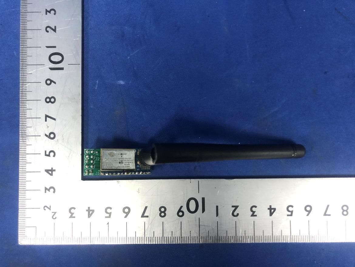
Click to zoom
Application Details
- Equipment Class
- DTS - Digital Transmission System
- Date of Grant
- Jul 09, 2022
- Application Purpose
- Original Equipment
- Date of Application
- Jul 09, 2022
- Equipment Note
- Radio Module
- Frequency Range
- 2402.00000000 - 2480.00000000
- Company
- Talon Communications, Inc.
- Country
- United States
Documents & Files
Document Text
Text extracted from the exhibit documents filed with the FCC. Open a document above to read the original.
Users Manual
Input excel file Revision 1.7 06/26/2022 The information in this document is subject to change without notice. 1/8 TALON COMMUNICATIONS San Diego - Ft. Collins - Ensenada WWW.TALONCOM.COM Copyright © 2022 Talon Communications, Inc. +20dBm Tango Sky INDUSTRIAL RADIOTRANSCEIVER MODULE DATASHEET DESCRIPTION Tango Sky is a low power, high over the air data rate, worldwide FCC/IC/CE/MIC certified 2.4GHz RF Module with a 100mW PA/LNA for extended range operations. Tango Sky is based on the Nordic nRF24L01+ radio incorporating an Enhanced ShockBurst™ hardware protocol accelerator which offloads time critical protocol functions from the application microcontroller enabling the implementation of advanced and robust wireless connectivity with low cost 3rd-party microcontrollers. Tango can be used with the nRFgo SDK for easy code development. The nRFgo SDK is a fully featured Software Development Kit for Nordic nRF24L Series 2.4GHz RF System-on-Chips (SoCs). Used in conjunction with the nRFgo Starter Kit and nRFgo Studio, it contains everything needed for code development and debugging, including integration with Keil μVision™ IDE, a comprehensive library of hardware abstraction layers (HAL), Nordic Gazell 2.4GHz RF protocol stack, USB stack, and example applications. The module brings out all the functional pins of the nRF24L01+ and PA for maximum usability and flexibility including: SPI Bus and Interrupt for Nordic nRF24L01+ control Power Amplifier software controlled TX, RX, Bypass and Sleep modes for complete PA control Power Amplifier automatic PA control via Nordic radio - No extra software required FEATURES • +20dBm (100mW) Maximum Transmit Power FCC/IC • +10dBm (10mW) Maximum Transmit Power CE/MIC •Micro 27mm x 14mm x 10mm form factor • Long range 1Km LoS @ +20dBm •Worldwide 2.4GHz ISM band operation •250Kbps / 1Mbps / 2Mbps selectable data rate •79 Selectable RF channels •Enhanced ShockBurst hardware accelerator •Automatic Packet Handling • Nordic Gazell Protocol Stack • Low power modes (<2μA in sleep mode) •4KV HBM Ruggedized •Nordic Radio plus PA/LNA •SMT or right angle through-hole mounting •-40C to +85C Operation •1.8v to 3.6v Operation • RoHS Compliant • FCC/IC/CE/MIC Certified APPLICATIONS •IoT •JPEG • M2M • Long Range Monitoring • Industrial Control •Commercial Automation • Lighting Control • Asset Tracking Input excel file Revision 1.7 06/26/2022 The information in this document is subject to change without notice. 2/8 TALON COMMUNICATIONS San Diego - Ft. Collins - Ensenada WWW.TALONCOM.COM Copyright © 2022 Talon Communications, Inc. +20dBm Tango Sky INDUSTRIAL RADIOTRANSCEIVER MODULE DATASHEET TANGO SKY PINOUT and PA TRUTH TABLE MODULE PIN # nRF24L01+ PIN # PIN NAME TYPE DESCRIPTION P1 7,15,18,19 VDD POWER 1.8 - 3.6V power supply 3.3v Typical P2 8,14,17,20 GND POWER GROUND P3 1 CE DIGITAL INPUT CHIP ENABLE ACTIVATES TX or RX, +5.0v Max. P4 2 CSN DIGITAL INPUT SPI CHIP SELECT (ACTIVE LOW) , +5.0v Max. P5 3 SCK DIGITAL INPUT SPI SERIAL DATA CLOCK, +5.0v Max. P6 4 MOSI DIGITAL INPUT SPI SLAVE DATA INPUT, +5.0v Max. *P7N/A BYPASS DIGITAL INPUT BYPASS = 1 PA ON BYPASS = 0 PA is bypassed (See below for Truth Table) P8 6 IRQ DIGITAL OUTPUT MASKABLE INTERRUPT (ACTIVE LOW) P9 5 MISO DIGITAL OUTPUT SPI SLAVE DATA OUTPUT (TRISTATE OPTION) P10 11 VDD_PA POWER For "auto PA control" CONNECT P10 to P11 then add 10K pullup to P12 SLEEP_N. *P11N/A TXEN_RXEN_N DIGITAL INPUT POWER AMPLIFIER TRANSMIT = 1, RECEIVE = 0 (See below for Truth Table) *P12N/A SLEEP_N DIGITAL INPUT POWER AMPLIFIER power OFF when = 0 (See below for Truth Table) P13 8,14,17,20 GND POWER GROUND *These PA/LNA signals have changed from the original Tango Module per Truth Table below Input excel file Revision 1.7 06/26/2022 The information in this document is subject to change without notice. 3/8 TALON COMMUNICATIONS San Diego - Ft. Collins - Ensenada WWW.TALONCOM.COM Copyright © 2022 Talon Communications, Inc. +20dBm Tango Sky INDUSTRIAL RADIOTRANSCEIVER MODULE DATASHEET TANGO MODULE DIMENSIONS / PADS Input excel file Revision 1.7 06/26/2022 The information in this document is subject to change without notice. 4/8 TALON COMMUNICATIONS San Diego - Ft. Collins - Ensenada WWW.TALONCOM.COM Copyright © 2022 Talon Communications, Inc. +20dBm Tango Sky INDUSTRIAL RADIOTRANSCEIVER MODULE DATASHEET MODULE RF CONNECTOR TCI-24SKY-RPSMA-RA TCI-24SKY-RPSMA-ST Right Angle RP-SMA Straight RP-SMA Tango Sky Ordering Information Input excel file Revision 1.7 06/26/2022 The information in this document is subject to change without notice. 5/8 TALON COMMUNICATIONS San Diego - Ft. Collins - Ensenada WWW.TALONCOM.COM Copyright © 2022 Talon Communications, Inc. +20dBm Tango Sky INDUSTRIAL RADIOTRANSCEIVER MODULE DATASHEET Warning: Changes or modifications to this unit not expressly approved by the party responsible for compliance could void the user’s authority to operate the equipment. NOTE: This equipment has been tested and found to comply with the limits for a Class B digital device, pursuant to Part 15 of the FCC Rules. These limits are designed to provide reasonable protection against harmful interference in a residential installation. This equipment generates, uses and can radiate radio frequency energy and, if not installed and used in accordance with the instructions, may cause harmful interference to radio communications. However, there is no guarantee that interference will not occur in a particular installation. If this equipment does cause harmful interference to radio or television reception, which can be determined by turning the equipment off and on, the user is encouraged to try to correct the interference by one or more of the following measures: Reorient or relocate the receiving antenna. Increase the separation between the equipment and receiver. Connect the equipment into an outlet on a circuit different from that to which the receiver is connected. Consult the dealer or an experienced radio/TV technician for help. This devi…
Text truncated - open the document above for the full version.
Attestation Statements
1(2) Talon Communications, Inc. RE FCC ID: A7D-TCI-24SKY To the certification reviewer: We are hereby applying for full modular approval of the above-referenced FCC ID, based on compliance with all of the criteria as detailed below. Sincerely, _________________ Scott McDermaid CEO Part 15 Unlicensed Single Modular Transmitter Approval Justifications per 15.212 Requirement per 15.212 Description (i)The radio elements of the modular transmitter must have their own RF shielding. Shielding is provided by a metal cover the circuitry. (ii)The modular transmitter must have buffered modulation/data inputs. All modulation and data inputs are buffered by circuitry on the transmitter chip. (iii)The modular transmitter must have its own power supply regulation. Power supply regulation is provided by circuitry on the transmitter chip. (iv)The modular transmitter must comply with the antenna and transmission system requirements of §§ 15.203, 15.204(b) and 15.204(c). The antenna is a unique removable antenna. (v)The modular transmitter must be tested in a stand-alone configuration, i.e., the module must not be inside another device during testing for compliance with Part 15 requirements. Testing was performed with the module extended outside of the host on a special extender boards, as shown in the test setup photos. 2(2) (vi) The modular transmitter must be equipped with either a permanently affixed label or must be capable of electronically displaying its FCC identification number. If the FCC ID is not visible when the module is installed inside another device, then the outside of the device into which the module is installed must also display a label referring to the enclosed module. See KDB Publication 784748. A sample of the host label is provided as an exhibit, showing the FCC ID of the module. (vii) The modular transmitter must comply with any specific rules or operating requirements that ordinarily apply to a complete transmitter and the manufacturer must provide adequate instructions along with the module to explain any such requirements. A copy of these instructions must be included in the application for equipment authorization. The modular transmitter complies with part 15 as demonstrated in the test report exhibit. (viii) The modular transmitter must comply with any applicable RF exposure requirements in its final configuration. The modular transmitter complies with RF exposure requirements as demonstrated in the RF exposure information exhibit.
Cover Letter(s)
Talon Communications, Inc. April 20, 2021 Federal Communications Commission 445 12 th Street SW Washington, DC 20554 Subject: Limited Agency Agreement Talon Communications, Inc. FCC ID: A7D-TCI-24SKY To Whom It May Concern: We, Talon Communications, Inc., hereby authorized Intertek Testing Services to act as our A gent for the purpose of preparing application for FCC ID number A7D-TCI-24SKY under all applicable parts of the FCC rules and regulations. The effective date of this limited agency agreement is April 20, 2021. The Limited Agency Agreement expires on April 19, 2031, unless sooner terminated or extended by written notice to Intertek Testing Services and the Federal Communications Commission. This is to advise that we are in full compliance with the Anti-Drug Abuse Act. The applicant is not subject to a denial of federal benefits pursuant to Section 5301 of the Anti-Drug Act of 1988, 21 U.S.C. 862, and no party to the application is subject to a denial of federal benefits pursuant to that section. If you have any questions or comments, please do not hesitate to contact me. Sincerely, Scott McDermaid CEO
Cover Letter(s)
1(2) Talon Commu nications, Inc. Attention : Certification reviewer RE: Request fo r Confidentiality FCC ID: A7D-TCI-24SKY To Whom It May Concern: Permanent Confidentiality [Complete this section if permanent confidentiality is requested] Request to withhold permanently from public review certain portions of the application for equipment certification for the referenced FCC identifiers. This request for confidentiality is made pursuant to 47 CFR 0.457(d) and 0.459 of the FCC Rules. In particular, the following sections of the application are to be kept permanently confidential: [Select one or more of items below, as appropriate] Schematics Block Diagrams Operational Descript ion Tune-up Procedure Parts List Internal P hotos (see note) Users Manual (see note) Note 1: Internal Photos may be held confidential 1) if the circuit board or internal components are not accessible to users. For example, it is acceptable if the circuit board is enclosed in epoxy. 2) Also, it is acceptable if the device is not accessible to the public, for example, a device mounted on the top of a large tower (or in a fenced enclosure) such that it is only serviceable by professional designated technicians under a Non-Disclosure Agreement (NDA). All sales for these devices must be under a NDA restricting the disclosure of the propriety information, including internal photos. Users Manual may be held confidential only when the manual contains proprietary technical information intended for professional technicians obligated under a NDA. All sales and distribution of the user’s manual must be under a NDA that restricts the disclosure of the information. In the application cover letter requesting permanent confidentiality the following additional description and the NDA exhibit is required: 1.Describe in detail how internal photos and/or users manual information are controlled to prevent them from becoming public or disclosed to unauthorized persons. 2.Describe how public access is restricted for products serviceable by professional designated technicians. 3.A statement that all sales of the non-consumer device will be under a NDA to include third party sales and that the final user of the device is subject to the NDA. 4.Provide an example of the NDA between the grantee and a purchaser. The request for confidentiality must Note 2: For scanning receiver, the schematics, block diagrams, operational description, tune-up procedure, parts list and internal photos are always held permanently confidential. Short-term Confidentiality [Complete this section if short-term confidentiality is requested] Request to withhold from public review for a period of 180 days from the date of the Grant of Equipment Authorization and prior to marketing, certain portions of the application for equipment certification for the referenced FCC identifiers. This request for confidentiality is made pursuant to 47 CFR 0.457(d) and 0.459 of the FCC Rules. In particular, the following sections of the application are to b e kept short- term confidential for a period above from the date of the grant [Select one or more of items below that are not selected in the list above, as appropriate] Schematics Block diagrams Operational Description Tune-up Procedure 2(2 ) Parts List Test Setup Photos External Phot os Internal Phot os Users Ma nual Ratio nale for request for confidentiality: We have in vested considerable time and materials in research and development to produce the referenced product. Permanent confidentiality: Disclosure of the permanently confidential portions of this application to competitors would not only give them significant competitive advantages in developing similar products, but would also disclose successful implementation of unpublished, leading edge technology developed by us. Short-term confidentiality: Disclosure of the short-term confidential portions of this application during the period of importation and/or distribution would reveal key aspects of proprietary technology to competitors and diminish the value of our investment in research and development. If you have questions or need further information, please contact the undersigned. Sin cerely, __________ _______ Scott McDermaid CEO April 20, 2021
External Photos
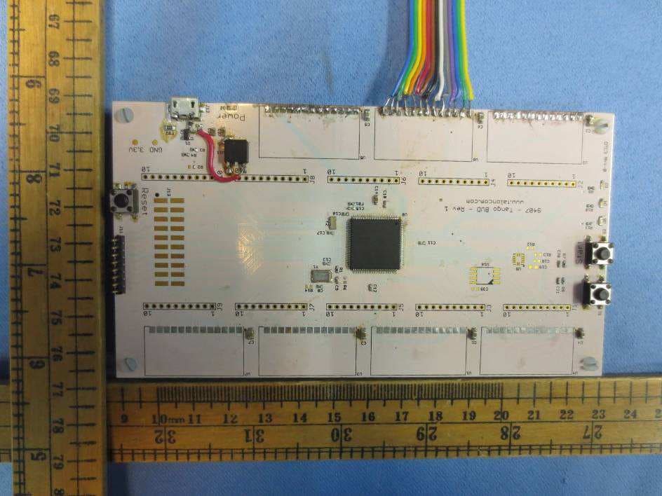
The module is installed on the test board, the test board is only used for testing and is not part of the product. test board module
ID Label/Location Info
Label Size: 9*14.5mm
Internal Photos
The module is installed on the test board, the test board is only used for testing and is not part of the product. test board module
RF Exposure Info
INTERTEK TESTING SERVICES RF Exposure The Equipment Under Test (EUT) is a Radio Module operating at 2402-2480MHz. The EUT is powered by DC 3.3V. For more detailed features description, please refer to the user’s manual. Antenna Type: removable antenna Antenna Gain: 2.0dBi Modulation Type: GFSK The nominal conducted output power specified: 20dBm (±1dB) The nominal radiation output power specified: 22dBm (±1dB) The maximun conducted output power for the EUT is 19.96dBm in the frequency 2440MHz which is within the production variation. The minimum conducted output power for the EUT is 19.70dBm in the frequency 2402MHz which is within the production variation. According to FCC Part 2.1091, this unlicensed transmitting device is categorically excluded from routine environmental evaluation for RF exposure prior to equipment authorization or use, According to the KDB 447498 and OET 65, the simple calculation as below: The source-based time averaged maximum radiated power = 23dBm = 199.53mW At the distance (R) of 20cm to 40cm and in 0.3 GHz to 6 GHz, MPE Exclusion Threshold Level: The MPE limit is 3060mW for general population and uncontrolled exposure in the 2.4GHz frequency range according to FCC Part 1.1307. As the measured power density at 20cm from the transmitter is lower than the MPE limit, the compliance to the MPE limit can be ensured by indicating the minimum 20cm separation between the transmitter's radiating structure and body of the user or nearby persons FCC ID: A7D-TCI-24SKY
Test Report
Talon Communications, Inc. TEST REPORT SCOPE OF WORK FCC TESTING–TCI-24SKY REPORT NUMBER 200303051SZN-001 ISSUE DATE [REVISED DATE] 30 June 2022 [--------------------] PAGES 34 DOCUMENT CONTROL NUMBER FCC ID 247_b © 2017 INTERTEK Intertek Report No.: 200303051SZN-001 This report is for the exclusive use of Intertek's Client and is provided pursuant to the agreement between Intertek and its Client. Intertek's responsibility and liability are limited to the terms and conditions of the agreement. Intertek assumes no liability to any party, other than to the Client in accordance with the agreement, for any loss, expense or damage occasioned by the use of this report. Only the Client is authorized to permit copying or distribution of this report and then only in its entirety. Any use of the Intertek name or one of its marks for the sale or advertisement of the tested material, product or service must first be approved in writing by Intertek. The observations and test results in this report are relevant only to the sample tested. This report by itself does not imply that the material, product, or service is or has ever been under an Intertek certification program. Intertek Testing Services Shenzhen Ltd. Longhua Branch 101, 201, Building B, No. 308 Wuhe Avenue, Zhangkengjing Community, GuanHu Subdistrict, LongHua District, Shenzhen, P.R. China. Tel: (86 755) 8601 6288 Fax: (86 755) 8601 6751 Version: 01-November-2017 Page: 1 of 34 FCC ID 247_b TEST REPORT 101, 201, Building B, No. 308 Wuhe Avenue, Zhangkengjing Community, GuanHu Subdistrict, LongHua District, Shenzhen, P.R. China. Tel: (86 755) 8601 6288 Fax: (86 755) 8601 6751 www.intertek.com Talon Communications, Inc. Application For Certification FCC ID: A7D-TCI-24SKY Radio Module Model: TCI-24SKY 2.4GHz Transceiver Report No.: 200303051SZN-001 We hereby certify that the sample of the above item is considered to comply with the requirements of FCC Part 15, Subpart C for Intentional Radiator, mention 47 CFR [10-1-20] Prepared and Checked by: Approved by: Jeff Liang Peter Kang Engineer Senior Technical Supervisor Date: 30 June 2022 Intertek Report No.: 200303051SZN-001 Version: 01-November-2017 Page: 2 of 34 FCC ID 247_b TEST REPORT MEASUREMENT/TECHNICAL REPORT This report concerns (check one) Original Grant X Class II Change Equipment Type: DTS - Part 15 Digital Transmission Systems (2.4GHz transmitter portion) Deferred grant requested per 47 CFR 0.457(d)(1)(ii)? Yes No X If yes, defer until : date Company Name agrees to notify the Commission by: date of the intended date of announcement of the product so that the grant can be issued on that date. Transition Rules Request per 15.37? Yes No X If no, assumed Part 15, Subpart C for intentional radiator - the new 47 CFR [10-01- 20] Edition] provision. Report prepared by: Jeff Liang Intertek Testing Services Shenzhen Ltd. Longhua Branch 101, 201, Building B, No. 308 Wuhe Avenue, Zhangkengjing Community, GuanHu Subdistrict, LongHua District, Shenzhen, P.R. China. Tel: (86 755) 8601 6288 Fax: (86 755) 8601 6661 Intertek Report No.: 200303051SZN-001 Version: 01-November-2017 Page: 3 of 34 FCC ID 247_b TEST REPORT Table of Contents 1.0 Summary of Test results ............................................................................................... 4 2.0 General Description ...................................................................................................... 5 2.1 Product Description ........................................................................................................... 5 2.2 Related Submittal(s) Grants ............................................................................................... 5 2.3 Test Methodology .............................................................................................................. 5 2.4 Test Facility ........................................................................................................................ 5 3.0 System Test Configuration ............................................................................................ 6 3.1 Justification ........................................................................................................................ 6 3.2 EUT Exercising Software ..................................................................................................... 6 3.3 Special Accessories ............................................................................................................ 6 3.4 Measurement Uncertainty ................................................................................................. 7 3.5 Equipment Modification .................................................................................................... 7 3.6 Support Equipment List and Description .......................................................................... 7 4.0 Measurement Results ................................................................................................... 8 4.1 Maximum Conducted Output Power at Antenna Terminals ................................................. 8 4.2 Minimum 6 dB RF Bandwidth ............................................................................................ 9 4.3 Maximum Power Density Reading ................................................................................... 11 4.4 Out of Band Conducted Emissions ................................................................................... 13 4.5 Out of Band Radiated Emissions ...................................................................................... 20 4.6 Transmitter Radiated Emissions in Restricted Bands ........................................................ 21 4.7 Field Strength Calculation ................................................................................................ 22 4.8 Radiated Spurious Emission ............................................................................................. 23 4.9 Conducted Em…
Text truncated - open the document above for the full version.
Test Setup Photos
The EUT and transmitting antenna was centered on the turntable. The EUT and transmitting antenna was centered on the turntable.
Contact Information
Applicant
Scott McDermaid
Technical Contact
Intertek Testing Services SZ Ltd Longhua BranchWilliam Chen
[email protected]86-755-86016288
101,201,Bldg B, No.308 Wuhe Ave, Zhangkenging Comm · Shenzhen · China
Non-Technical Contact
Intertek Testing Services SZ Ltd Longhua BranchWilliam Chen
[email protected]86-755-86016288
Test Firm
Intertek Testing Services Shenzhen Ltd. Longhua BrHolly Ou
[email protected]+86 755 86140691
Technical Specifications
| # | Rule Parts | Frequency Range | Power Output |
|---|---|---|---|
| 1 | 15C | 2.40 GHz - 2.48 GHz | 99.08 mW |
Other Applications from Talon Communications, Inc.
A7D-24NOD-PA100
Dec 09, 2012Radio Module
Equipment Class
DXX - Part 15 Low Power Communication Device Transmitter