A7KST-WHDMI WI-FI Smart TV Stick
AWOX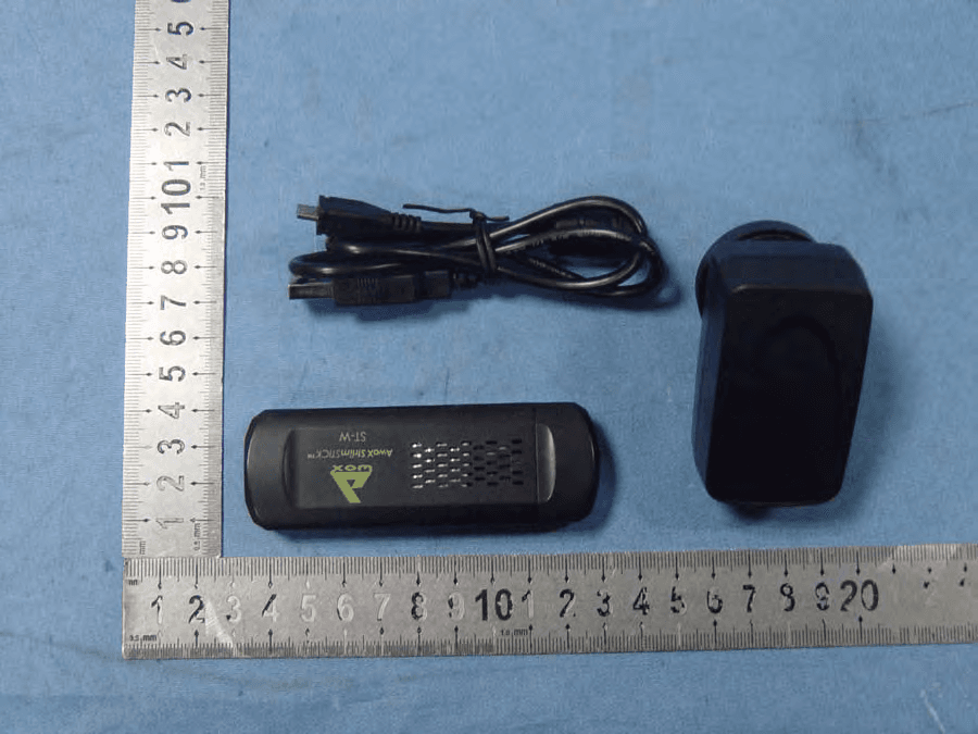
Click to zoom
Application Details
- Equipment Class
- DTS - Digital Transmission System
- Date of Grant
- Apr 21, 2013
- Application Purpose
- Original Equipment
- Date of Application
- Apr 21, 2013
- Equipment Note
- HDMI WI-FI Smart TV Stick
- Frequency Range
- 2422.00000000 - 2452.00000000
- Company
- AWOX
- Country
- France
Documents & Files
Document Text
Text extracted from the exhibit documents filed with the FCC. Open a document above to read the original.
Users Manual
AwoX StriimSTICK Wi-Fi smart TV stick ST-W User guide www.awoxstriim.com AwoX StriimSTICK User Guide | 1 EN Contents Welcome ............................................................................. 2 AwoX StriimSTICK overview ................................................ 3 Remote control ................................................................... 4 AwoX StriimSTICK setup ...................................................... 6 AwoX StiimSTICK applications ............................................. 9 Technical specifications ..................................................... 11 © 2013 AwoX. All rights reserved. StriimSTICK, AwoX, the AwoX logo and other AwoX marks are owned by AwoX. The “Android” name, the logo, and other trademarks are property of Google Inc. All other trademarks are the property of their respective owners. Information contained in this document is non-contractual. AwoX StriimStick User Guide rev 02. www.awoxstriim.com AwoX StriimSTICK User Guide | 2 EN Welcome Congratulations and thank you for choosing the AwoX StriimSTICK™ smart TV adapter. Simply plug this Android™ smart stick into any TV’s HDMI input and surf the Internet over a Wi-Fi connection and run your applications just like on a tablet or smartphone. Enjoy this powerful and easy-to-use Wi-Fi / Internet HDMI smart stick to: Use your TV just like an Android- powered tablet or smartphone Access the on-line store to download thousands of applications Share your photos, listen to music, stream videos Access the Internet and your on-line services Use your on-line e-mail accounts Take the AwoX StriimSTICK with you when you travel... use it anywhere you have a TV and Wi-Fi Internet access! This guide will show you how to set up your AwoX StriimSTICK™ adapter and turn your TV into an Android-powered smart TV in a few easy steps. www.awoxstriim.com AwoX StriimSTICK User Guide | 3 EN AwoX StriimSTICK overview What’s in the box StriimSTICK HDMI dongle to plug into your TV Remote control for StriimSTICK USB-to-Micro USB power cable to provide power to StriimSTICK AC adapter with USB port (in case TV’s USB does not supply enough power) HDMI extension cable Note: The StriimSTICK dongle has a micro-SD card slot that supports cards up to 32 GB Before your begin: Charge your remote control using the provided USB cable. www.awoxstriim.com AwoX StriimSTICK User Guide | 4 EN Remote control Your AwoX StriimSTICK includes a remote control to control an arrow-cursor on your TV screen. Use this remote control exactly like a traditional mouse, as well as to simulate various swipe movements supported by the Android operating system. The following pictures show the various features of your remote control: On/off switch Volume up / down USB charging port Reactivate www.awoxstriim.com AwoX StriimSTICK User Guide | 5 EN OK and “swipe” To perform on-screen swipe actions with your mouse, press and hold the OK key and move the mouse cursor on the screen. Recharging the remote control battery To recharge the battery in your remote control, simply unplug the USB charging cable from the StriimSTICK dongle when you are not using it, and insert the cable into the micro-USB port on the “OK” button in center, directional navigation buttons Cursor control: up, down, right, left Home Back www.awoxstriim.com AwoX StriimSTICK User Guide | 6 EN remote control. The battery should last a week or more depending on use. Reactivating the mouse on your TV screen To save power, the mouse switches to standby mode when not used for a few minutes. To reactive it simply press the reactivate button ( button on the left-hand side of the remote control). AwoX StriimSTICK setup Set up StriimSTICK on your TV 1. Plug the remote control adapter into the top of the StriimSTICK. 2. Plug the micro-USB connector into the appropriate port on StriimSTICK for power. Plug the other USB cable end into a USB port on your TV. 3. Plug the StriimSTICK into a free HDMI port on your TV. If it is difficult to position the dongle directly, use the provided HDMI extension cable. 4. Turn on your TV. The StriimSTICK takes about 1 minute to startup fully. Note: if your TV displays a message that it is unable to read the www.awoxstriim.com AwoX StriimSTICK User Guide | 7 EN StriimSTICK as “add-on media” or similar, simply dismiss the message and proceed. 5. If the outout power from the TV’s USB port is insufficient, or if the TV displays an error, plug the cable into the provided AC adapter instead, and then plug the adapter into a wall socket. 6. Use your regular TV remote control to select the appropriate HDMI port to view the StriimSTICK welcome screen. 7. On the remote control, slide the ON/OFF switch to “ON” to display the cursor on your TV screen. www.awoxstriim.com AwoX StriimSTICK User Guide | 8 EN First-time use: the AwoX setup wizard The AwoX Setup wizard runs the first time you plug your AwoX StriimSTICK into your TV. Follow the simple steps on your TV screen to: Choose the display language Connect to your home Wi-Fi router and enter your router’s password (note: some routers may be case-sensitive to the characters you enter here). Set your time zone. At the end of the Wizard you are ready to use your remote control to navigate around the interface. For more details on using the Android system, apps and other features, please see www.google.com. If you would like to run the wizard again, go into Applications and click on the icon shown here. www.awoxstriim.com AwoX StriimSTICK User Guide | 9 EN AwoX StiimSTICK applications Runs standard Android applications The Android operating system was developed for a wide variety of mobile devices, including smartphones, tablets, set-top TV boxes and consumer electronics/entertainment equipment. Offering the numerous features found in these various types of connected multimedia/Internet terminals, StriimSTICK supports the same applications as other Android devices. You may purchase a…
Text truncated - open the document above for the full version.
Attestation Statements
AW O X April 15, 2013 To: Federal Communications Commission Authorization and Evaluation Division 7435 Oakland Mills Road Columbia, MD FCC ID: A7KST-W To Whom It May Concern: This letter is to ascertain that AW O X (Product:HDMI WI-FI Smart TV Stick Model name: ST-W) has been the units used for conducting FCC compliance testing, the DoC part will be tested by FCC recognized test lab. If you have any question or concerns, pls. contact us. Sincerely, Client’s signature: Client’s name / title: CADIERE JF / Program Manager Contact information / address: 93 Place Pierre Duhem Montpellier 34000 France
Cover Letter(s)
AW O X April 15, 2013 To: SIEMIC, INC. 775 Montague Expressway Milpitas , CA 95035 USA Dear Sir/Madam, Re: Project and Product Certification Representative Authorization Letter We , AW O X hereby authorize SIEMIC, INC. to act as a Certification Body for certifying for the following project(s): Product Description: HDMI WI-FI Smart TV Stick Model name: ST-W FCC ID: A7KST-W We affirm that between SIEMIC and AW O X , any difference in understanding, including test plan, measurement methods, applicable standards and relevant procedures and processes have been resolved prior to commencement of testing activities. Sincerely, Client’s signature: Client’s name / title: CADIERE JF / Program Manager Contact information / address: 93 Place Pierre Duhem Montpellier 34000 France
Cover Letter(s)
SCS-F19: Confidentiality Request Letter Page 1 of 1 Rev 2.0 AWOX April 15, 2013 To: Federal Communications Commission Authorization and Evaluation Division 7435 Oakland Mills Road Columbia, MD Confidentiality Request regarding application for certification of FCC ID: A7KST-W We hereby request confidential treatment of information accompanying this application as outlined below: - Block Diagram - Operational Description - Schematic The above materials contain trade secrets and proprietary information not customarily released to the public. The public disclosure of these materials may be harmful to the applicant and provide unjustified benefits to its competitors. The applicant understands that pursuant to Section 0.457 & 0.459 of the Rules, disclosure of this application and all accompanying documentation will not be made before the date of the Grant for this application. Client’s signature: Client’s name / title: CADIERE JF / Program Manager Contact information / address: 93 Place Pierre Duhem Montpellier 34000 France
ID Label/Location Info
FCC Certification Label Location Sample Label location
ID Label/Location Info
FCC Certification label Sample FCC ID: A7KST-W IC: 10994A-STW AWOX MODEL NO.: ST-W This device complies with Part 15 of the FCC Rules. Operation is subject to the following two conditions: (1) This device may not cause harmful interference, and (2) This device must accept any interference received, including interference that ma y cause undesired operation.
Internal Photos
Antenna
RF Exposure Info
FCC ID : A7KST-W 1. RF EXPOSURE 1.1. The Requirement System operating under the provisions of this section shall be operated in a manner that ensures that the public is not exposed to radio frequency energy levels in excess of the Commission’s guidelines. See Section 15.247(b)(4) and Section 1.1307(b)(1) 1.2. Limit For Maximum Permissible Exposure (MPE) Limits for General Population/ Uncontrolled Exposure F = frequency in MHz, * Plane-wave equivalent power density 1.3. MPE Calculations E(V/m) = 30 P G d , Power Density: S( 2 mW/cm) = 2 377 E Where E = Electric Field (V/m) P = Peak Output Power (mW) Frequency Range (MHz) Electric Field Strength (E) (V/m) Magnetic Field Strength (H) (A/m) Power Density (S) ( 2 mW/cm) Averaging Time 2 E, 2 H or S (minutes) 0.3-1.34 614 1.63 (100)* 30 1.34-30 824/f 2.19/f (180/f)* 30 30-300 27.5 0.073 0.2 30 300-1500 f/1500 30 1500-100,000 1.0 30 G = Antenna Numeric Gain (numeric) = 10 x , x = Antenna Gain(dBi) /10 d = Separation Distance (cm) We can change the formula to: S = 2 30 377 PG d or, d = 30 377 PG S Because the EUT is belong to general population/uncontrolled exposure. So 1.3.1. We considering the limit of minimum separation distance (d) is 20cm, Maximum Output Power = 8.99 Antenna Gain = 2(dBi) = 1.58(numeric) S = 2 30 377 PG d = 2.8*10 -3 < 1.0 2 mW/cm (limit) Calculated RF Exposure power density is 2.8*10 -3 2 mW/cm , less than the limit. 1.3.2. We considering the limit of power density (S) is 1.0 2 mW/cm , Maximum Output Power = 8.99 Antenna Gain = 2(dBi) = 1.58 (numeric) d = 30 377 PG S = 1.06< 20 cm Calculated RF Exposure separation distance is 1.06 less than the minimum separation distance 1.3.3.FCC Radiation Exposure Statement This equipment complies with FCC radiation exposure limits set forth for an uncontrolled environment. In order to avoid the possibility of exceeding the FCC radio frequency exposure limits, Human proximity to the antenna shall not be less than 20cm(8 inches) during normal operation. Proposed RF exposure safety information to include in User’s Manual.
Test Report
Page 1 of 199 FCC ID: A7KST-W ACCURATE TECHNOLOGY CO., LTD Report No.: ATE20130457 APPLICATION CERTIFICATION FCC Part 15C On Behalf of AWOX HDMI WI-FI Smart TV Stick Model No.: ST-W FCC ID: A7KST-W Prepared for : AWOX Address : 93 Place Pierre Duhem Montpellier 34000 France Prepared by : ACCURATE TECHNOLOGY CO., LTD Address : F1, Bldg. A, Changyuan New Material Port, Keyuan Rd. Science & Industry Park, Nanshan, Shenzhen, Guangdong P.R. China Tel: (0755) 26503290 Fax: (0755) 26503396 Report Number : ATE20130457 Date of Test : March 21- April 15, 2013 Date of Report : April 15, 2013 Page 2 of 199 FCC ID: A7KST-W ACCURATE TECHNOLOGY CO., LTD Report No.: ATE20130457 TABLE OF CONTENTS Description Page Test Report Certification 1. GENERAL INFORMATION .......................................................................................................... 5 1.1. Description of Device (EUT)....................................................................................................................5 1.2. Carrier Frequency of Channels .................................................................................................................6 1.3. Test Procedure ..........................................................................................................................................6 1.4. Special Accessory and Auxiliary Equipment ...........................................................................................6 1.5. Description of Test Facility ......................................................................................................................7 1.6. Measurement Uncertainty.........................................................................................................................7 2. MEASURING DEVICE AND TEST EQUIPMENT ..................................................................... 8 3. OPERATION OF EUT DURING TESTING ................................................................................. 9 3.1. Operating Mode ........................................................................................................................................9 3.2. Configuration and peripherals ..................................................................................................................9 4. TEST PROCEDURES AND RESULTS ....................................................................................... 10 5. 6DB BANDWIDTH MEASUREMENT ........................................................................................ 11 5.1. Block Diagram of Test Setup..................................................................................................................11 5.2. The Requirement For Section 15.247(a)(2) ............................................................................................11 5.3. EUT Configuration on Measurement .....................................................................................................11 5.4. Operating Condition of EUT ..................................................................................................................11 5.5. Test Procedure ........................................................................................................................................12 5.6. Test Result ..............................................................................................................................................12 6. MAXIMUM PEAK OUTPUT POWER ....................................................................................... 26 6.1. Block Diagram of Test Setup..................................................................................................................26 6.2. The Requirement For Section 15.247(b)(3)............................................................................................26 6.3. EUT Configuration on Measurement .....................................................................................................26 6.4. Operating Condition of EUT ..................................................................................................................26 6.5. Test Procedure ........................................................................................................................................27 6.6. Test Result ..............................................................................................................................................28 7. POWER SPECTRAL DENSITY MEASUREMENT.................................................................. 42 7.1. Block Diagram of Test Setup..................................................................................................................42 7.2. The Requirement For Section 15.247(e).................................................................................................42 7.3. EUT Configuration on Measurement .....................................................................................................42 7.4. Operating Condition of EUT ..................................................................................................................42 7.5. Test Procedure ........................................................................................................................................43 7.6. Test Result ..............................................................................................................................................44 8. BAND EDGE COMPLIANCE TEST ........................................................................................... 58 8.1. Block Diagram of Test Setup..................................................................................................................58 8.2. The Requirement For Section 15.247(d) ................................................................................................58 8.3. EUT Configuration on Measurement ...............................................................…
Text truncated - open the document above for the full version.
Test Report
Page 101 of 199 FCC ID: A7KST-W ACCURATE TECHNOLOGY CO., LTD Report No.: ATE20130457 Date of Test: March 25 & April 11, 2013 Temperature: 25 o C EUT: HDMI WI-FI Smart TV Stick Humidity: 50% Model No.: ST-W Power Supply: AC 120V/60Hz Test Mode: 802.11g Channel High 2462MHz Test Engineer: Pei For Below 30MHz Reading (dBV/m) Result (dBV/m) Limit (dBV/m) Margin (dB) Frequency (MHz) QP Factor(dB) Corr. QP QP QP Polarization - - - - - - X - - - - - - Y - - - - - - Z For 30MHz-1000MHz Corrected Factor = Antenna Factor + Cable Loss – Amplifier Gain Reading (dBV/m) Result (dBV/m) Limit (dBV/m) Margin (dB) Frequency (MHz) QP Factor Corr. (dB) QP QP QP Polarization 428.0192 46.92 -14.22 32.70 46.00 -13.30 866.0878 43.79 -6.69 37.10 46.00 -8.90 962.1622 40.08 -5.23 34.85 54.00 -19.15 Vertical 396.2414 44.57 -15.67 28.90 46.00 -17.10 866.0878 45.02 -6.69 38.33 46.00 -7.67 962.1622 41.52 -5.23 36.29 54.00 -17.71 Horizontal For 1GHz-25GHz Corrected Factor = Antenna Factor + Cable Loss – Amplifier Gain Reading(dBV/m)Result(dBV/m)Limit(dBV/m)Margin(dBV/m) Frequency (MHz) AV PEAK Factor Corr. (dB) AV PEAKAV PEAK AV PEAK Polarizati on - - - - - - - - - - Vertical - - - - - - - - - - Horizontal Note: 1. Emissions attenuated more than 20 dB below the permissible value are not reported. 2. *: Denotes restricted band of operation. 3. The fundamental radiated emissions were reduced by Band Reject Filter in the attached plots. Page 102 of 199 FCC ID: A7KST-W ACCURATE TECHNOLOGY CO., LTD Report No.: ATE20130457 Date of Test: March 25 & April 11, 2013 Temperature: 25 o C EUT: HDMI WI-FI Smart TV Stick Humidity: 50% Model No.: ST-W Power Supply: AC 120V/60Hz Test Mode: 802.11n Channel Low 2412MHz (20MHz) Test Engineer: Pei For Below 30MHz Reading (dBV/m) Result (dBV/m) Limit (dBV/m) Margin (dB) Frequency (MHz) QP Factor(dB) Corr. QP QP QP Polarization - - - - - - X - - - - - - Y - - - - - - Z For 30MHz-1000MHz Corrected Factor = Antenna Factor + Cable Loss – Amplifier Gain Reading (dBV/m) Result (dBV/m) Limit (dBV/m) Margin (dB) Frequency (MHz) QP Factor Corr. (dB) QP QP QP Polarization 432.5457 48.89 -14.15 34.74 46.00 -11.26 866.0879 43.81 -6.69 37.12 46.00 -8.88 962.1623 41.77 -5.23 36.54 54.00 -17.46 Vertical 385.2805 46.24 -15.77 30.47 46.00 -15.53 824.5968 47.46 -7.39 40.07 46.00 -5.93 866.0879 45.07 -6.69 38.38 46.00 -7.62 Horizontal For 1GHz-25GHz Corrected Factor = Antenna Factor + Cable Loss – Amplifier Gain Reading(dBV/m ) Result(dBV/m)Limit(dBV/m)Margin(dBV/m) Frequency (MHz) AV PEAK Factor Corr. (dB) AV PEAKAV PEAK AV PEAK Polarizati on - - - - - - - - - - Vertical - - - - - - - - - - Horizontal Note: 1. Emissions attenuated more than 20 dB below the permissible value are not reported. 2. *: Denotes restricted band of operation. 3. The fundamental radiated emissions were reduced by Band Reject Filter in the attached plots. Page 103 of 199 FCC ID: A7KST-W ACCURATE TECHNOLOGY CO., LTD Report No.: ATE20130457 Date of Test: March 25 & April 11, 2013 Temperature: 25 o C EUT: HDMI WI-FI Smart TV Stick Humidity: 50% Model No.: ST-W Power Supply: AC 120V/60Hz Test Mode: 802.11n Channel Middle 2437MHz (20MHz) Test Engineer: Pei For Below 30MHz Reading (dBV/m) Result (dBV/m) Limit (dBV/m) Margin (dB) Frequency (MHz) QP Factor(dB) Corr. QP QP QP Polarization - - - - - - X - - - - - - Y - - - - - - Z For 30MHz-1000MHz Corrected Factor = Antenna Factor + Cable Loss – Amplifier Gain Reading (dBV/m) Result (dBV/m) Limit (dBV/m) Margin (dB) Frequency (MHz) QP Factor Corr. (dB) QP QP QP Polarization 437.1198 49.10 -14.10 35.00 46.00 -11.00 866.0878 44.10 -6.69 37.41 46.00 -8.59 962.1622 41.77 -5.23 36.54 54.00 -17.46 Vertical 674.6225 43.97 -15.82 28.15 46.00 -17.85 813.1115 49.49 -7.55 41.64 46.00 -4.36 866.0879 44.42 -6.69 37.73 46.00 -8.27 Horizontal For 1GHz-25GHz Corrected Factor = Antenna Factor + Cable Loss – Amplifier Gain Reading(dBV/m)Result(dBV/m)Limit(dBV/m)Margin(dBV/m) Frequency (MHz) AV PEAK Factor Corr. (dB) AV PEAKAV PEAK AV PEAK Polarizati on - - - - - - - - - - Vertical - - - - - - - - - - Horizontal Note: 1. Emissions attenuated more than 20 dB below the permissible value are not reported. 2. *: Denotes restricted band of operation. 3. The fundamental radiated emissions were reduced by Band Reject Filter in the attached plots. Page 104 of 199 FCC ID: A7KST-W ACCURATE TECHNOLOGY CO., LTD Report No.: ATE20130457 Date of Test: March 25 & April 11, 2013 Temperature: 25 o C EUT: HDMI WI-FI Smart TV Stick Humidity: 50% Model No.: ST-W Power Supply: AC 120V/60Hz Test Mode: 802.11n Channel High 2462MHz (20MHz) Test Engineer: Pei For Below 30MHz Reading (dBV/m) Result (dBV/m) Limit (dBV/m) Margin (dB) Frequency (MHz) QP Factor(dB) Corr. QP QP QP Polarization - - - - - - X - - - - - - Y - - - - - - Z For 30MHz-1000MHz Corrected Factor = Antenna Factor + Cable Loss – Amplifier Gain Reading (dBV/m) Result (dBV/m) Limit (dBV/m) Margin (dB) Frequency (MHz) QP Factor Corr. (dB) QP QP QP Polarization 432.5457 48.86 -14.15 34.71 46.00 -11.29 866.0879 44.66 -6.69 37.97 46.00 -8.03 962.1623 41.11 -5.23 35.88 54.00 -18.12 Vertical 370.7022 43.85 -15.85 28.00 46.00 -18.00 866.0878 45.27 -6.69 38.58 46.00 -7.42 962.1622 41.02 -5.23 35.79 54.00 -18.21 Horizontal For 1GHz-25GHz Corrected Factor = Antenna Factor + Cable Loss – Amplifier Gain Reading(dBV/m)Result(dBV/m)Limit(dBV/m)Margin(dBV/m) Frequency (MHz) AV PEAK Factor Corr. (dB) AV PEAKAV PEAK AV PEAK Polarizati on - - - - - - - - - - Vertical - - - - - - - - - - Horizontal Note: 1. Emissions attenuated more than 20 dB below the permissible value are not reported. 2. *: Denotes restricted band of operation. 3. The fundamental radiated emissions were reduced by Band Reject Filter in the attached plots. Page 105 of 199 FCC ID: A7KST-W ACCURATE TECHNOLOGY CO., LTD Report No.: ATE20130457 Date of Test: March 25 & April 11, 2013 Temperature: 25 o C EUT: HDMI WI-FI Smart TV Stick Humidity: 50% Model No.: ST-W Power Supply: AC 120V/60H…
Text truncated - open the document above for the full version.
Test Report
Page 151 of 199 FCC ID: A7KST-W ACCURATE TECHNOLOGY CO., LTD Report No.: ATE20130457 Page 152 of 199 FCC ID: A7KST-W ACCURATE TECHNOLOGY CO., LTD Report No.: ATE20130457 Page 153 of 199 FCC ID: A7KST-W ACCURATE TECHNOLOGY CO., LTD Report No.: ATE20130457 Page 154 of 199 FCC ID: A7KST-W ACCURATE TECHNOLOGY CO., LTD Report No.: ATE20130457 Page 155 of 199 FCC ID: A7KST-W ACCURATE TECHNOLOGY CO., LTD Report No.: ATE20130457 Page 156 of 199 FCC ID: A7KST-W ACCURATE TECHNOLOGY CO., LTD Report No.: ATE20130457 Page 157 of 199 FCC ID: A7KST-W ACCURATE TECHNOLOGY CO., LTD Report No.: ATE20130457 Page 158 of 199 FCC ID: A7KST-W ACCURATE TECHNOLOGY CO., LTD Report No.: ATE20130457 Page 159 of 199 FCC ID: A7KST-W ACCURATE TECHNOLOGY CO., LTD Report No.: ATE20130457 Page 160 of 199 FCC ID: A7KST-W ACCURATE TECHNOLOGY CO., LTD Report No.: ATE20130457 Page 161 of 199 FCC ID: A7KST-W ACCURATE TECHNOLOGY CO., LTD Report No.: ATE20130457 Page 162 of 199 FCC ID: A7KST-W ACCURATE TECHNOLOGY CO., LTD Report No.: ATE20130457 Page 163 of 199 FCC ID: A7KST-W ACCURATE TECHNOLOGY CO., LTD Report No.: ATE20130457 Page 164 of 199 FCC ID: A7KST-W ACCURATE TECHNOLOGY CO., LTD Report No.: ATE20130457 Page 165 of 199 FCC ID: A7KST-W ACCURATE TECHNOLOGY CO., LTD Report No.: ATE20130457 Page 166 of 199 FCC ID: A7KST-W ACCURATE TECHNOLOGY CO., LTD Report No.: ATE20130457 Page 167 of 199 FCC ID: A7KST-W ACCURATE TECHNOLOGY CO., LTD Report No.: ATE20130457 Page 168 of 199 FCC ID: A7KST-W ACCURATE TECHNOLOGY CO., LTD Report No.: ATE20130457 Page 169 of 199 FCC ID: A7KST-W ACCURATE TECHNOLOGY CO., LTD Report No.: ATE20130457 Page 170 of 199 FCC ID: A7KST-W ACCURATE TECHNOLOGY CO., LTD Report No.: ATE20130457 Page 171 of 199 FCC ID: A7KST-W ACCURATE TECHNOLOGY CO., LTD Report No.: ATE20130457 Page 172 of 199 FCC ID: A7KST-W ACCURATE TECHNOLOGY CO., LTD Report No.: ATE20130457 Page 173 of 199 FCC ID: A7KST-W ACCURATE TECHNOLOGY CO., LTD Report No.: ATE20130457 Page 174 of 199 FCC ID: A7KST-W ACCURATE TECHNOLOGY CO., LTD Report No.: ATE20130457 Page 175 of 199 FCC ID: A7KST-W ACCURATE TECHNOLOGY CO., LTD Report No.: ATE20130457 Page 176 of 199 FCC ID: A7KST-W ACCURATE TECHNOLOGY CO., LTD Report No.: ATE20130457 Page 177 of 199 FCC ID: A7KST-W ACCURATE TECHNOLOGY CO., LTD Report No.: ATE20130457 Page 178 of 199 FCC ID: A7KST-W ACCURATE TECHNOLOGY CO., LTD Report No.: ATE20130457 Page 179 of 199 FCC ID: A7KST-W ACCURATE TECHNOLOGY CO., LTD Report No.: ATE20130457 Page 180 of 199 FCC ID: A7KST-W ACCURATE TECHNOLOGY CO., LTD Report No.: ATE20130457 10. CONDUCTED SPURIOUS EMISSION COMPLIANCE TEST 10.1.Block Diagram of Test Setup (EUT: HDMI WI-FI Smart TV Stick) 10.2.The Requirement For Section 15.247(d) Section 15.247(d): In any 100 kHz bandwidth outside the frequency band in which the spread spectrum or digitally modulated intentional radiator is operating, the radio frequency power that is produced by the intentional radiator shall be at least 20 dB below that in the 100 kHz bandwidth within the band that contains the highest level of the desired power, based on either an RF conducted or a radiated measurement, provided the transmitter demonstrates compliance with the peak conducted power limits. If the transmitter complies with the conducted power limits based on the use of RMS averaging over a time interval, as permitted under paragraph (b)(3) of this section, the attenuation required under this paragraph shall be 30 dB instead of 20 dB. Attenuation below the general limits specified in Section 15.209(a) is not required. In addition, radiated emissions which fall in the restricted bands, as defined in Section 15.205(a), must also comply with the radiated emission limits specified in Section 15.209(a). 10.3.EUT Configuration on Measurement The following equipment is installed on the emission measurement to meet the commission requirements and operating regulations in a manner which tends to maximize its emission characteristics in normal application. 10.3.1.HDMI WI-FI Smart TV Stick (EUT) Model Number : ST-W Serial Number : N/A Manufacturer : NEWMI TECH.(HK)CO., LTD. Low Loss Cable Spectrum Analyzer EUT Page 181 of 199 FCC ID: A7KST-W ACCURATE TECHNOLOGY CO., LTD Report No.: ATE20130457 10.4.Operating Condition of EUT 10.4.1.Setup the EUT and simulator as shown as Section 10.1. 10.4.2.Turn on the power of all equipment. 10.4.3.Let the EUT work in TX modes measure it. The transmit frequency are 2412-2462 and 2422-2452MHz. We select 2412MHz, 2437MHz, 2462MHz and 2422MHz, 2437MHz, 2452MHz TX frequency to transmit. 10.5.Test Procedure 10.5.1.The transmitter output was connected to the spectrum analyzer via a low loss cable. 10.5.2.Set RBW of spectrum analyzer to 100kHz and VBW to 300kHz (below 1GHz). 10.5.3.Set RBW of spectrum analyzer to 1MHz and VBW to 3MHz (above 1GHz). 10.5.4.The Conducted Spurious Emission was measured and recorded. 10.6.Test Result Pass. The spectrum analyzer plots are attached as below. Page 182 of 199 FCC ID: A7KST-W ACCURATE TECHNOLOGY CO., LTD Report No.: ATE20130457 TX 802.11b Channel Low 2412MHz (30MHz-1GHz) TX 802.11b Channel Low 2412MHz (1GHz-25GHz) Page 183 of 199 FCC ID: A7KST-W ACCURATE TECHNOLOGY CO., LTD Report No.: ATE20130457 TX 802.11b Channel Middle 2437MHz (30MHz-1GHz) TX 802.11b Channel Middle 2437MHz (1GHz-25GHz) Page 184 of 199 FCC ID: A7KST-W ACCURATE TECHNOLOGY CO., LTD Report No.: ATE20130457 TX 802.11b Channel High 2462MHz (30MHz-1GHz) TX 802.11b Channel High 2462MHz (1GHz-25GHz) Page 185 of 199 FCC ID: A7KST-W ACCURATE TECHNOLOGY CO., LTD Report No.: ATE20130457 TX 802.11g Channel Low 2412MHz (30MHz-1GHz) TX 802.11g Channel Low 2412MHz (1GHz-25GHz) Page 186 of 199 FCC ID: A7KST-W ACCURATE TECHNOLOGY CO., LTD Report No.: ATE20130457 TX 802.11g Channel Middle 2437MHz (30MHz-1GHz) TX 802.11g Channel Middle 2437MHz Page 187 of 199 FCC ID: A7KST-W ACCURATE TECHNOLOGY CO., LTD Report No.: ATE20130457 TX 802.11g Channel High 2462MHz (30MHz-1GHz) TX 802.11g Channel High 2462MHz (1GHz-25GHz) Pa…
Text truncated - open the document above for the full version.
Test Setup Photos
Conducted emissions test Radiated emissions test < 30MHz Radiated emissions test 30MHz- 1GHz Radiated emissions test > 1GHz
Contact Information
Applicant
CADIERE JF(PROGRAM MANAGER)
Test Firm
Accurate Technology Co., Ltd.Sean Liu
Technical Specifications
| # | Rule Parts | Frequency Range | Power Output |
|---|---|---|---|
| 2 | 15C | 2.42 GHz - 2.45 GHz | 8.07 mW |
Other Applications from AWOX
A7K-ALBC7
Jun 20, 2015Smart LED Light
Equipment Class
DXX - Part 15 Low Power Communication Device Transmitter
A7K-SLCW13
Dec 22, 2014AwoX StriimLIGHTTM Wi-Fi Color
Equipment Class
DTS - Digital Transmission System
A7K-SLCB13
Aug 19, 2014AwoX StriimLIGHTTM Color
Equipment Class
DXX - Part 15 Low Power Communication Device Transmitter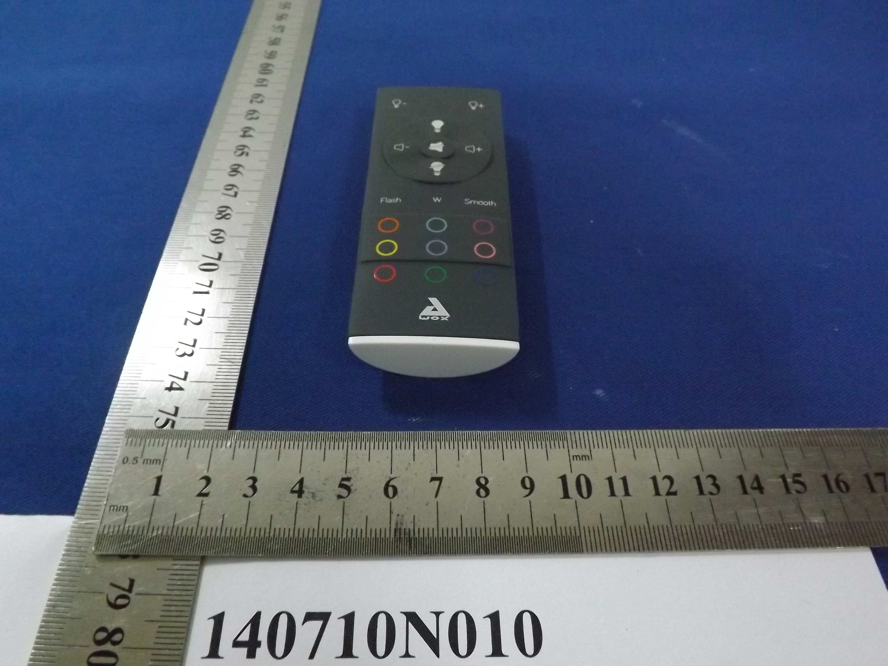
A7K-SLMCB3
Aug 19, 2014AwoX StriimLIGHTTM mini Color
Equipment Class
DXX - Part 15 Low Power Communication Device Transmitter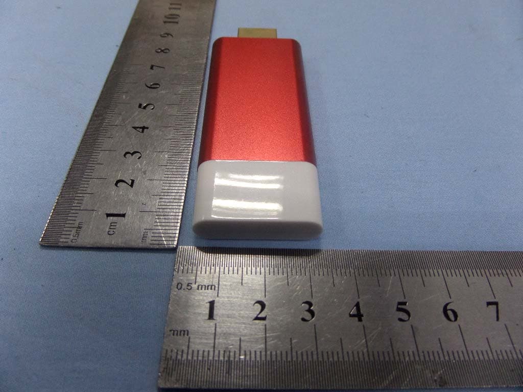
A7K-SCW
Jun 16, 2014Awox StriimCAST
Equipment Class
DTS - Digital Transmission System