Text extracted from the exhibit documents filed with the FCC. Open a document above to read the original.
Model 95A04-2 Bluetooth Remote Input Module (BRIM) 95I04-2 Home Automation, Inc. DESCRIPTION The Bluetooth Remote Input Module (BRIM) is a remote audio input (Bluetooth or wired) and infrared output module designed to be installed in rooms that will have music sources. Bluetooth devices can connect and act as a music server or a wired audio source can be connected directly to the BRIM, which allows that music to be shared with any audio zone in the house. Each BRIM ships with an IR flasher that is used for sending IR data to source equipment. When you point your source equipment remote control at the IR receiver in a VSC and send a signal, the IR data is routed to the appropriate BRIM (to which the source is logically connected), which then sends the IR signal through the IR flasher to the source equipment. INSTALLATION Remote Input Modules connect directly to the Hi-Fi2 Main Assembly using Cat 5, unshielded, twisted pair (UTP) for communications. Each end of the wire is terminated with an RJ45 connector. The correct wiring scheme for the Cat 5 cable is standard EIA/TIA 568A. Properly terminating the Cat 5 cable is crucial for the operation of the system. It is best that no single run of Cat 5 exceeds 500 feet. Insert the RJ45 connector on one end of the cable to the respective source input jack (1-8) under “Remote Audio In / IR Out” on the Hi-Fi2 Main Assembly. Insert the RJ45 connector on the other end of the cable to the jack labeled “Remote Audio” on the BRIM. SETTING THE FREQUENCY OF THE IR OUTPUT When using the BRIM to send IR data to source equipment, there are two different IR carrier frequencies in which the BRIM can transmit the IR signal. The default setting of 38 kHz is used for most audio sources. However, most cable and satellite converter boxes operate at a higher IR carrier frequency closer to 56 kHz. Each BRIM has a switch that allows you to change the frequency of the IR output when using such devices. To change the frequency setting, remove the faceplate and insert from the BRIM using a small-blade screwdriver and gently depress each latch on one side while lifting up on the insert. Once the latches are released on one side, remove the insert from the other side. Once the insert has been removed, move the frequency switch (SW1) from the “38kHz” position to the “56kHz” position. Reinstall the insert by aligning the latches of the insert to the openings on the BRIM and gently snapping it into place. Then, attach the faceplate. 38kHz 56kHz TOP FREQUENCY SWITCH SW1 Page 2 BLUETOOTH To pair a Bluetooth device to the BRIM, simply find the BRIM in the list of Bluetooth devices and connect. When a Bluetooth device is paired with the BRIM, the LED above the HAI logo will glow blue, and then you can play audio from application running on the device (such as Pandora, Spotify, Rhapsody, iTunes, and YouTube) in any Hi-Fi2 audio zone. IR OUTPUT Each BRIM ships with an IR flasher (62A08-1). The IR flasher is used for sending IR data to the source equipment. When you point your source equipment remote control at the IR receiver in the VSC and send a signal, the IR data is routed to the appropriate BRIM (to which the source is connected), which then sends the IR signal through the IR flasher to the source equipment. FEDERAL COMMUNICATIONS COMMISSION INTERFERENCE STATEMENT This device complies with Part 15 of the FCC Rules. Operation is subject to the condition that this device does not cause harmful interference. This mobile device meets guidelines for exposure to radio waves. Your mobile device is a radio transmitter and receiver. It is designed not to exceed the limits for exposure to radio waves recommended by international guidelines. This equipment has been tested and found to comply with the limits for a Class B digital device, pursuant to Part 15 of the FCC Rules. These limits are designed to provide reasonable protection against harmful interference in a residential installation. This equipment generates, uses, and can radiate radio frequency energy and, if not installed and used in accordance with the instructions, may cause harmful interference to radio communications. However, there is no guarantee that interference will not occur in a particular installation. If this equipment does cause harmful interference to radio or television reception, which can be determined by turning the equipment off and on, the user is encouraged to try to correct the interference by one or more of the following measures: --Reorient or relocate the receiving antenna. --Increase the separation between the equipment and receiver. --Connect the equipment into an outlet on a circuit different from that to which the receiver is connected. --Consult the dealer or an experienced radio/TV technician for help. CAUTION: Any changes or modifications not expressly approved by the grantee of this device could void the user's authority to operate the equipment. Body-worn operations are restricted to belt-clips, holsters, or similar accessories that have no metallic component in the assembly and must provide at least 1.5 cm separation between the device and the user’s body. RF exposure warning: The equipment complies with FCC RF exposure limits set forth for an uncontrolled environment. The equipment must not be co-located or operating in conjunction with any other antenna or transmitter. IC Radiation Exposure Statement for Canada This device complies with Industry Canada license-exempt RSS standard(s). Operation is subject to the following two conditions: (1) this device may not cause interference, and (2) this device must accept any interference, including interference that may cause undesired operation of the device. Le présent appareil est conforme aux CNR d'Industrie Canada applicables aux appareils radio exempts de licence. L'exploitation est autorisée aux deux conditions suivantes : (1) l'appareil ne doit pas produire de brouillage, et (2) l'utilisateur de l'appareil doit accepter tout brouillage radioél…
Text truncated - open the document above for the full version.
Hangzhou NUVO Electronics Co. Ltd. Attestation for FCC Declaration of Conformity FCC ID: A8G-95A042 Date: 2012/06/21 Please be notified that we, the undersigned, Hangzhou NUVO Electronics Co. Ltd. declares that the product which bears the above FCC ID is also compliant with the FCC requirements for DOC. And the DoC procedure shall be carried out prior to marketing the device in the US. Sincerely, Amy Mi / Prject Manager Hangzhou NUVO Electronics Co. Ltd.
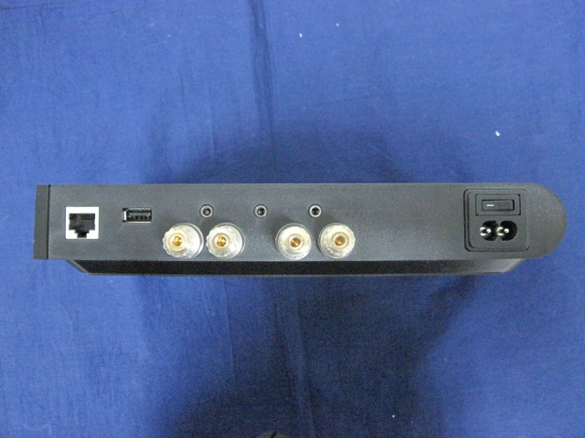
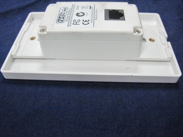
1. EUT Photograph (1) EUT Photo (2) EUT Photo (3) EUT Photo (4) EUT Photo (5) EUT Photo (6) EUT Photo
(1) EUT Photo (2) EUT Photo (3) EUT Photo (4) EUT Photo
RF Exposure Evaluation Declaration Product Name : Bluetooth Remote Input Module Model No. : 95A04-2 FCC ID : A8G-95A042 IC : 7246A-95A042 Applicant : Hangzhou NUVO Electronics Co. Ltd. Address : No.8, Jiaqi Road, Xianlin Street, Yuhang District, Hangzhou Date of Receipt : 18/05/2012 Issued Date : 19/06/2012 Report No. : 125S044R-RF-US-P20V01 Report Version : V1.0 The test results relate only to the samples tested. The test results shown in the test report are traceable to the national/international standard through the calibration of the equipment and evaluated measurement uncertainty herein. This report must not be used to claim product endorsement by TAF, CNAS or any agency of the Government. The test report shall not be reproduced except in full without the written approval of QuieTek Corporation. Report No: 125S044R-RF-US-P20V01 Page: 2 of 5 Test Report Certification Issued Date : 19/06/2012 Report No. : 125S044R-RF-US-P20V01 Product Name : Bluetooth Remote Input Module Applicant : Hangzhou NUVO Electronics Co. Ltd. Address : No.8, Jiaqi Road, Xianlin Street, Yuhang District, Hangzhou Manufacturer : Hangzhou NUVO Electronics Co. Ltd. Address : No.8, Jiaqi Road, Xianlin Street, Yuhang District, Hangzhou Model No. : 95A04-2 FCC ID : A8G-95A042 IC : 7246A-95A042 EUT Voltage : AC 100-240V / 50-60Hz Test Voltage : 120V / 60Hz Brand Name : HAI Applicable Standard : FCC OET 65 RSS-102: Issue 4, March, 2010 Test Result : Complied Performed Location : Suzhou EMC Laboratory No.99 Hongye Rd., Suzhou Industrial Park Loufeng Hi-Tech Development Zone., Suzhou, China TEL: +86-512-6251-5088 / FAX: +86-512-6251-5098 FCC Registration Number: 800392; IC Lab Code: 4075B Documented By : (Engineering ADM: Alice Ni) Reviewed By : (Senior Engineer: Jame Yuan) Approved By : (Manager: Marlin Chen) Report No: 125S044R-RF-US-P20V01 Page: 3 of 5 Laboratory Information We, QuieTek Corporation, are an independent EMC and safety consultancy that was established the whole facility in our laboratories. The test facility has been accredited/accepted(audited or listed) by the following related bodies in compliance with ISO 17025, EN 45001 and specified testing scope: The related certificate for our laboratories about the test site and management system can be downloaded from QuieTek Corporation’s Web Site :http://www.quietek.com/tw/ctg/cts/accreditations.htm The address and introduction of QuieTek Corporation’s laboratories can be founded in our Web site : http://www.quietek.com/ If you have any comments, Please don’t hesitate to contact us. Our contact information is as below: HsinChu Testing Laboratory : No.75-2, 3rd Lin, Wangye Keng, Yonghxing Tsuen, Qionglin Shiang, Hsinchu County 307, Taiwan, R.O.C. TEL:+886-3-592-8858 / FAX:+886-3-592-8859 E-Mail : [email protected] LinKou Testing Laboratory : No.5-22, Ruishukeng, Linkou Dist., New Taipei City 24451, Taiwan, R.O.C. TEL : 886-2-8601-3788 / FAX : 886-2-8601-3789 E-Mail : [email protected] Suzhou Testing Laboratory : No.99 Hongye Rd., Suzhou Industrial Park Loufeng Hi-Tech Development Zone., SuZhou, China TEL : +86-512-6251-5088 / FAX : 86-512-6251-5098 E-Mail : [email protected] Taiwan R.O.C. :BSMI, NCC, TAF Germany :TUV Rheinland Norway :Nemko, DNV USA :FCC, NVLAP Japan :VCCI China :CNAS Report No: 125S044R-RF-US-P20V01 Page: 4 of 5 1. RF Exposure Evaluation 1.1. Limits According to FCC 1.1310: The criteria listed in the following table shall be used to evaluate the environment impact of human exposure to radio frequency (RF) radiation as specified in 1.1307(b) LIMITS FOR MAXIMUM PERMISSIBLE EXPOSURE (MPE) Frequency Range (MHz) Electric Field Strength (V/m) Magnetic Field Strength (A/m) Power Density (mW/cm2) Average Time (Minutes) (A) Limits for Occupational/ Control Exposures 300-1500 -- -- F/300 6 1500-100,000 -- -- 5 6 (B) Limits for General Population/ Uncontrolled Exposures 300-1500 -- -- F/1500 6 1500-100,000 -- -- 1 30 F= Frequency in MHz Friis Formula Friis transmission formula: Pd = (Pout*G)/(4*pi*r2) Where Pd = power density in mW/cm2 Pout = output power to antenna in mW G = gain of antenna in linear scale Pi = 3.1416 R = distance between observation point and center of the radiator in cm Pd id the limit of MPE, 1 mW/cm2 . If we know the maximum gain of the antenna and the total power input to the antenna, through the calculation, we will know the distance r where the MPE limit is reached. Report No: 125S044R-RF-US-P20V01 Page: 5 of 5 1.2. Test Procedure Software provided by client enabled the EUT to transmit and receive data at lowest, middle and highest channel individually. The temperature and related humidity: 18°Cand 78% RH. 1.3. Test Result of RF Exposure Evaluation Product : Bluetooth Remote Input Module Test Item : RF Exposure Evaluation Test Site : AC-6 Antenna Gain: Antenna Gain: The maximum Gain measured in fully anechoic chamber is 2.0dBi in logarithm scale. Output Power into Antenna & RF Exposure Evaluation Distance: Frequency Band (MHz) Maximum Output Power to Antenna (mW) Power Density at R = 20 cm (mW/cm2) 2402 - 2480 MHz 1.7338 0.000547 Note: The power density Pd (4th column) at a distance of 20 cm calculated from the Friis transmission formula is far below the limit of 1 mW/cm2.
Test Report FCC Part15 Subpart C Product Name : Bluetooth Remote Input Module Model No. : 95A04-2 FCC ID : A8G-95A042 IC : 7246A-95A042 Applicant : Hangzhou NUVO Electronics Co. Ltd. Address : No.8, Jiaqi Road, Xianlin Street, Yuhang District, Hangzhou Date of Receipt : 18/05/2012 Test Date : 19/05/2012~11/06/2012 Issued Date : 19/06/2012 Report No. : 125S044R-RF-US-P06V01 Report Version : V 1.1 The test results relate only to the samples tested. The test results shown in the test report are traceable to the national/international standard through the calibration of the equipment and evaluated measurement uncertainty herein. This report must not be used to claim product endorsement by TAF, CNAS or any agency of the Government. The test report shall not be reproduced except in full without the written approval of QuieTek Corporation. Report No: 125S044R-RF-US-P06V01 Page: 2 of 116 Test Report Certification Issued Date : 19/06/2012 Report No. : 125S044R-RF-US-P06V01 Product Name : Bluetooth Remote Input Module Applicant : Hangzhou NUVO Electronics Co. Ltd. Address : No.8, Jiaqi Road, Xianlin Street, Yuhang District, Hangzhou Manufacturer : Hangzhou NUVO Electronics Co. Ltd. Address : No.8, Jiaqi Road, Xianlin Street, Yuhang District, Hangzhou Model No. : 95A04-2 FCC ID : A8G-95A042 IC : 7246A-95A042 EUT Voltage : AC 100-240V / 50-60Hz Test Voltage : 120V / 60Hz Brand Name : HAI Applicable Standard : FCC CFR Title 47 Part 15 Subpart C: 2011 ANSI C63.4: 2009; ANSI C63.10: 2009 Industry Canada RSS-Gen Issue 3/RSS-210 Issue 8 Test Result : Complied Performed Location : Suzhou EMC Laboratory No.99 Hongye Rd., Suzhou Industrial Park Loufeng Hi-Tech Development Zone., Suzhou, China TEL: +86-512-6251-5088 / FAX: +86-512-6251-5098 FCC Registration Number: 800392; IC Lab Code: 4075B Documented By : (Engineering ADM: Alice Ni) Reviewed By : (Senior Engineer: Jame Yuan) Approved By : (Manager: Marlin Chen) Report No: 125S044R-RF-US-P06V01 Page: 3 of 116 Laboratory Information We, QuieTek Corporation, are an independent EMC and safety consultancy that was established the whole facility in our laboratories. The test facility has been accredited/accepted(audited or listed) by the following related bodies in compliance with ISO 17025, EN 45001 and specified testing scope: The related certificate for our laboratories about the test site and management system can be downloaded from QuieTek Corporation’s Web Site :http://www.quietek.com/tw/ctg/cts/accreditations.htm The address and introduction of QuieTek Corporation’s laboratories can be founded in our Web site : http://www.quietek.com/ If you have any comments, Please don’t hesitate to contact us. Our contact information is as below: HsinChu Testing Laboratory : No.75-2, 3rd Lin, Wangye Keng, Yonghxing Tsuen, Qionglin Shiang, Hsinchu County 307, Taiwan, R.O.C. TEL:+886-3-592-8858 / FAX:+886-3-592-8859 E-Mail : [email protected] LinKou Testing Laboratory : No.5-22, Ruishukeng, Linkou Dist., New Taipei City 24451, Taiwan, R.O.C. TEL : 886-2-8601-3788 / FAX : 886-2-8601-3789 E-Mail : [email protected] Suzhou Testing Laboratory : No.99 Hongye Rd., Suzhou Industrial Park Loufeng Hi-Tech Development Zone., SuZhou, China TEL : +86-512-6251-5088 / FAX : 86-512-6251-5098 E-Mail : [email protected] Taiwan R.O.C. :BSMI, NCC, TAF Germany :TUV Rheinland Norway :Nemko, DNV USA :FCC, NVLAP Japan :VCCI China :CNAS Report No: 125S044R-RF-US-P06V01 Page: 4 of 116 TABLE OF CONTENTS Description Page 1. General Information........................................................................................................7 1.1. EUT Description .........................................................................................................7 1.2. Mode of Operation .....................................................................................................9 1.3. Tested System Details..............................................................................................10 1.4. Configuration of Tested System ............................................................................... 11 1.5. EUT Exercise Software ............................................................................................12 2. Technical Test ...............................................................................................................13 2.1. Summary of Test Result ...........................................................................................13 2.2. Test Environment.....................................................................................................14 3. Conducted Emission ....................................................................................................15 3.1. Test Equipment ........................................................................................................15 3.2. Test Setup ................................................................................................................15 3.3. Limit..........................................................................................................................16 3.4. Test Procedure.........................................................................................................16 3.5. Uncertainty ...............................................................................................................16 3.6. Test Result...............................................................................................................17 4. Radiated Emission .......................................................................................................19 4.1. Test Equipment ........................................................................................................19 4.2. Test Setup ................................................................................................................20 4.3. Limit.............................................................................................…
Text truncated - open the document above for the full version.
1. Test Setup Photograph Description: Front View of Conducted Emission Test Setup Description: Back View of Conducted Emission Test Setup Description: Radiated Emission Test Setup for Below 30MHz Description: Radiated Emission Test Setup for Below 1GHz Description: Radiated Emission Test Setup for Above 1GHz Description: Radiated Emission Test Setup for Above 18GHz
| # | Rule Parts | Frequency Range | Power Output |
|---|---|---|---|
| 1 | 15C | 2.40 GHz - 2.48 GHz | 1.70 mW |

Power Amplifier
Equipment Class
DSS - Part 15 Spread Spectrum Transmitter