FCCID.CO- FCC ID Database
HomeCompaniesEquipment ClassesSearch

© 2026 FCC ID Database. All rights reserved.

AboutContactData sourced from FCC public records
  1. Home/
  2. Hangzhou NUVO Electronics Co. Ltd./
  3. A8G-NUVOWPMG

A8G-NUVOWPMGPower Amplifier

Hangzhou NUVO Electronics Co. Ltd.
Power Amplifier - FCC ID A8G-NUVOWPMG - Hangzhou NUVO Electronics Co. Ltd.
Click to zoom

Application Details

Equipment Class
DSS - Part 15 Spread Spectrum Transmitter
Date of Grant
Apr 16, 2012
Application Purpose
Original Equipment
Date of Application
Apr 16, 2012
Equipment Note
Power Amplifier
Frequency Range
2402.00000000 - 2480.00000000
Company
Hangzhou NUVO Electronics Co. Ltd.
Country
China

Documents & Files

Select a file to view
Users Manual

↗

Cover Letter(s)

↗
↗
↗

External Photos

↗

ID Label/Location Info

↗

Internal Photos

↗

RF Exposure Info

↗

Test Report

↗

Test Setup Photos

↗

Document Text

Text extracted from the exhibit documents filed with the FCC. Open a document above to read the original.

Users Manual

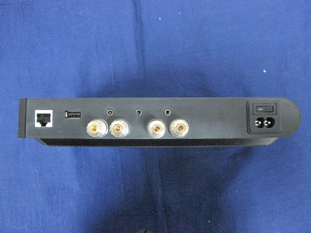
1 Player Portfolio Manual Player Portfolio Models NV-P100 Zone Player NV-P200 Zone Player NV-P3100 Three Zone Player NV-GW100 Wireless Gateway NV-CR100 Wireless Controller Introduction Welcome to the exciting world of the NuVo Player Portfolio. Now your favorite music anywhere you want it, anytime you want it is as close as the touch of a button on the NuVo Wireless Controller or any of your Apple or Android Wi-Fi enabled portable devices. T rue high fidelity music from your own personal library or streaming from the Internet, is more affordable and accessible than you ever imagined. The Player Portfolio has the flexibility of two amplified Wireless Players that easily connect to the home’s network through the NV-GW100 dual band gateway. The setup is quick and the communication is very robust. In addition, the NV-P3100 is a rack mountable component that connects directly to the network and provides a “hardwired” solution that is perfect for installations that already have traditionally installed speakers. This is your guide to quickly and easily filling a home with music. 2 3 4 The NuVo Wireless Player Portfolio System is comprised of: 1. Players – NV-P100, NV-P200, or NV-P3100 2. Wireless Gatew ay – NV-GW100 3. Router and an Internet connection 4. Wireless control – NV-CR100 and / or iPhone, IPad, IPod Touch, Android phone or Android Tablet 5 NV-P100 Features 1. Ethernet:This RJ-45 port allows for a wired connection directly to the NV- GW100 Gateway or directly to the network router. 2.USB:Any USB enabled hard drive can share music content with the Player Portfolio System through this port. 3.Audio In:This 3.5mm stereo input will accept any analog line level audio signal. The local audio source is amplified by the local Player, as well as providing it as an additional source selection in any other associated audio zones within the Player Portfolio System. 4.Audio Out:This 3.5mm stereo output provides the local line level audio signal to an additional amplifier, powered subwoofer, or headphones. 5.Left and Right Speaker Outputs:These binding posts provide an amplified local audio signal to any connected speakers. The maximum output of the NV- P100 is 40 watts stereo. 6.AC Input:The universal power supply will accept 100 – 240VAC, 50-60Hz. 6 NV-P200 Features 1. Ethernet:This RJ-45 port allows for a wired connection directly to the NV- GW100 Gateway or directly to the network router. 2. USB:Any USB enabled hard drive can share music content with the Player Portfolio System through this port. 3.Audio In:This 3.5mm stereo input will accept any analog line level audio signal. The local audio source is amplified by the local Player, as well as providing it as an additional source selection in any other associated audio zones within the Player Portfolio System. 4. Audio Out:This 3.5mm stereo output provides the local line level audio signal to an additional amplifier, powered subwoofer, or headphones. 5. Setup Mic:This 3.5mm input is designed for the Audyssey® calibration mic. Audyssey features a room equalization algorithm built-into the Player Portfolio user control. This calibration is very useful for compensating for poor room acoustics or speaker placement. The Audyssey mic is sold separately. 6.Left and Right Speaker Outputs:These binding posts provide an amplified local audio signal to any connected speakers. The maximum output of the NV- P200 is 120 watts stereo. 7.AC Input:The universal power supply will accept 100 – 240VAC, 50-60Hz. . 7 NV-P3100 Features 1. Ethernet:The NV-P3100 is designed to connect directly to the network. The second port enables multiple P3100’s to share the same network connection within one system. 2.Speaker:This modular connection provides a maximum 40 watt stereo amplified signal to the connected speakers. Each zone represents an independent output. 3.Line In:This 3.5mm stereo input will accept any analog line level audio signal. The local audio source is amplified by the local Player, as well as providing it as an additional source selection in any other associated audio zones within the Player Portfolio System. Each zone represents an independent input. 4.Trigger In:This 3.5mm input acts as an input control from external equipment. Each zone represents an independent input. 5.Line Out:This 3.5mm stereo output provides the local line level audio signal to an additional amplifier, powered subwoofer, or headphones. Each zone represents an independent output. 6. Trigger Out:This 3.5mm output acts as a voltage trigger for external equipment. Each zone represents an independent output. 7.USB:Any USB enabled hard drive can share music content with the Player Portfolio System through this port. zone represents an independent input. 8.Setup:This button is used for each of the Zone sections in the setup process to associate the zone control with the network. 9.AC Input:The universal power supply will accept 100 – 240VAC, 50-60Hz. 8 1. Setup/Installation 1.1 Network requirements A live Internet connection is not necessary for basic functionality and accessing music that is stored on a hard drive on the network, but keep in mind that a live access to the Internet is necessary at initial setup. The Player System does use the web to verify the user license associated with each Player being installed and will automatically check for updates to the firmware and software. A minimum 100Mbps wired network in necessary for proper communication. This should not be a problem. T oday’s network routers are designed to operate in the Gigabyte range. If this is not the case, you should update the installation’s network equipment before you proceed with the Player Portfolio setup. 1.2 Connecting the Gateway to the Network The NV-GW100 Wireless Gateway is the central communication point for the Wireless Players and control. It requires a standard Ethernet CAT 5, CAT5e or CAT6 cable. It should be a standard EIA/TIA 568A or 568B network termination, as shown in fig. 1. Note that this is …

Text truncated - open the document above for the full version.

Cover Letter(s)

Hangzhou NUVO Electronics Co. Ltd. Date:Mar. 20, 2012 Federal Communications Commission Authorization and Evaluation Division FCC ID: A8G-NUVOWPMG IC : 7246A-NUVOWPMG Confidentiality Request Pursuant to Sections 0.457 and 0.459 of the Commission’s Rules, the Applicant hereby requests confidential treatment of information accompanying this Application as outlined below: 1 Schematics 2 Block Diagram 3 Operational Description The above materials contain trade secrets and proprietary information not customarily released to the public. The public disclosure of these matters might be harmful to the Applicant and provide unjustified benefits to its competitors. Sincerely, Amy Mi/Project Manager Hangzhou NUVO Electronics Co. Ltd.

Cover Letter(s)

Hangzhou NUVO Electronics Co. Ltd. Attestation for FCC Declaration of Conformity FCC ID: A8G-NUVOWPMG Date: 2012/04/05 Please be notified that we, the undersigned, Hangzhou NUVO Electronics Co. Ltd. declares that the product which bears the above FCC ID is also compliant with the FCC requirements for DOC. And the DoC procedure shall be carried out prior to marketing the device in the US. Sincerely, Amy Mi / Prject Manager Hangzhou NUVO Electronics Co. Ltd.

External Photos

1. EUT Photograph (1) EUT Photo (2) EUT Photo (3) EUT Photo (4) EUT Photo (5) EUT Photo (6) EUT Photo

Internal Photos

(1) EUT Photo (2) EUT Photo (3) EUT Photo (4) EUT Photo (5) EUT Photo (6) EUT Photo (7) EUT Photo (8) EUT Photo (9) EUT Photo (10) EUT Photo (11) EUT Photo (12) EUT Photo

RF Exposure Info

RF Exposure Evaluation Declaration Product Name : Power Amplifier Model No. : NV-P200 FCC ID : A8G-NUVOWPMG IC : 7246A-NUVOWPMG Applicant : Hangzhou NUVO Electronics Co. Ltd. Address : No.8, Jiaqi Road, Xianlin Street, Yuhang District, Hangzhou Date of Receipt : 06/02/2012 Issued Date : 16/02/2012 Report No. : 11CS042R-RF-US-P20V01 Report Version : V1.1 The test results relate only to the samples tested. The test results shown in the test report are traceable to the national/international standard through the calibration of the equipment and evaluated measurement uncertainty herein. This report must not be used to claim product endorsement by TAF, NVLAP, NIST or any agency of the Government. The test report shall not be reproduced except in full without the written approval of QuieTek Corporation. Report No: 11CS042R-RF-US-P20V01 Page: 2 of 5 Test Report Certification Issued Date : 16/02/2012 Report No. : 11CS042R-RF-US-P20V01 Product Name : Power Amplifier Applicant : Hangzhou NUVO Electronics Co. Ltd. Address : No.8, Jiaqi Road, Xianlin Street, Yuhang District, Hangzhou Manufacturer : Hangzhou NUVO Electronics Co. Ltd. Address : No.8, Jiaqi Road, Xianlin Street, Yuhang District, Hangzhou Model No. : NV-P200 FCC ID : A8G-NUVOWPMG IC : 7246A-NUVOWPMG EUT Voltage : 90-240vac Brand Name : NUVO Applicable Standard : FCC OET 65 RSS-102: Issue 4, March, 2010 Test Result : Complied Performed Location : Suzhou EMC Laboratory No.99 Hongye Rd., Suzhou Industrial Park Loufeng Hi-Tech Development Zone., Suzhou, China TEL: +86-512-6251-5088 / FAX: +86-512-6251-5098 FCC Registration Number: 800392; IC Lab Code: 4075B Documented By : (Engineering ADM: Alice Ni) Reviewed By : (Senior Engineer: Jame Yuan) Approved By : (Engineering Manager: Marlin Chen) Report No: 11CS042R-RF-US-P20V01 Page: 3 of 5 Laboratory Information We, QuieTek Corporation, are an independent EMC and safety consultancy that was established the whole facility in our laboratories. The test facility has been accredited/accepted(audited or listed) by the following related bodies in compliance with ISO 17025, EN 45001 and specified testing scope: The related certificate for our laboratories about the test site and management system can be downloaded from QuieTek Corporation’s Web Site : http://www.quietek.com/tw/ctg/cts/accreditations.htm The address and introduction of QuieTek Corporation’s laboratories can be founded in our Web site : http://www.quietek.com/ If you have any comments, Please don’t hesitate to contact us. Our contact information is as below: HsinChu Testing Laboratory : No.75-2, 3rd Lin, Wangye Keng, Yonghxing Tsuen, Qionglin Shiang, Hsinchu County 307, Taiwan, R.O.C. TEL:+886-3-592-8858 / FAX:+886-3-592-8859 E-Mail : [email protected] LinKou Testing Laboratory : No. 5-22, Ruei-Shu Valley, Ruei-Ping Tsuen, Lin-Kou Shiang, Taipei, Taiwan, R.O.C. TEL : 886-2-8601-3788 / FAX : 886-2-8601-3789 E-Mail : [email protected] Suzhou (China) Testing Laboratory : No. 99 Hongye Rd., Suzhou Industrial Park Loufeng Hi-Tech Development Zone., Suzhou,China. TEL : +86-512-6251-5088 / FAX : +86-512-6251-5098 E-Mail : [email protected] Taiwan R.O.C. :BSMI, NCC, TAF Germany :TUV Rheinland Norway :Nemko, DNV USA :FCC, NVLAP Japan :VCCI Report No: 11CS042R-RF-US-P20V01 Page: 4 of 5 1. RF Exposure Evaluation 1.1. Limits According to FCC 1.1310: The criteria listed in the following table shall be used to evaluate the environment impact of human exposure to radio frequency (RF) radiation as specified in 1.1307(b) LIMITS FOR MAXIMUM PERMISSIBLE EXPOSURE (MPE) Frequency Range (MHz) Electric Field Strength (V/m) Magnetic Field Strength (A/m) Power Density (mW/cm2) Average Time (Minutes) (A) Limits for Occupational/ Control Exposures 300-1500 -- -- F/300 6 1500-100,000 -- -- 5 6 (B) Limits for General Population/ Uncontrolled Exposures 300-1500 -- -- F/1500 6 1500-100,000 -- -- 1 30 F= Frequency in MHz Friis Formula Friis transmission formula: Pd = (Pout*G)/(4*pi*r2) Where Pd = power density in mW/cm2 Pout = output power to antenna in mW G = gain of antenna in linear scale Pi = 3.1416 R = distance between observation point and center of the radiator in cm Pd id the limit of MPE, 1 mW/cm2 . If we know the maximum gain of the antenna and the total power input to the antenna, through the calculation, we will know the distance r where the MPE limit is reached. Report No: 11CS042R-RF-US-P20V01 Page: 5 of 5 1.2. Test Procedure Software provided by client enabled the EUT to transmit and receive data at lowest, middle and highest channel individually. The temperature and related humidity: 18°Cand 78% RH. 1.3. Test Result of RF Exposure Evaluation Product : Power Amplifier Test Item : RF Exposure Evaluation Test Site : AC-6 Antenna Gain: Antenna Gain-WLAN: The maximum Gain measured in fully anechoic chamber is 1.4dBi o for 2.4G and 2.9dBi for 5G. Antenna Gain-BT: The maximum Gain measured in fully anechoic chamber is 2dBi in logarithm scale. Output Power into Antenna & RF Exposure Evaluation Distance: WLAN Test Mode Frequency Band (MHz) Maximum Output Power to Antenna (mW) Power Density at R = 20 cm (mW/cm2) 802.11b/g/n(20MHz) 2412~2462 110.1539 0.030250 802.11n(40MHz) 2422~2452 79.6159 0.021864 802.11a/n(20MHz) 5745~5825 15.0314 0.005831 802.11n(40MHz) 5755~5795 14.7231 0.005711 BT Frequency Band (MHz) Maximum Output Power to Antenna (mW) Power Density at R = 20 cm (mW/cm2) 2402 - 2480 MHz 1.0765 0.000339 Note: The power density Pd (4th column) at a distance of 20 cm calculated from the Friis transmission formula is far below the limit of 1 mW/cm2. The product's function BT/WLAN can't work simultaneous;

Test Report

Test Report Industry Canada RSS-Gen Issue 3/RSS-210 Issue 8 FCC Part15 Subpart C Product Name : Power Amplifier Model No. : NV-P200 FCC ID : A8G-NUVOWPMG IC : 7246A-NUVOWPMG Applicant : Hangzhou NUVO Electronics Co. Ltd. Address : No.8, Jiaqi Road, Xianlin Street, Yuhang District, Hangzhou Date of Receipt : 14/12/2011 Test Date : 13/02/2012~22/02/2012 Issued Date : 23/02/2012 Report No. : 11CS042R-RF-US-P06V01 Report Version : V1.1 Report No: 11CS042R-RF-US-P06V01 Page: 2 of 117 Test Report Certification Issued Date : 23/02/2012 Report No. : 11CS042R-RF-US-P06V01 Product Name : Power Amplifier Applicant : Hangzhou NUVO Electronics Co. Ltd. Address : No.8, Jiaqi Road, Xianlin Street, Yuhang District, Hangzhou Manufacturer : Hangzhou NUVO Electronics Co. Ltd. Address : No.8, Jiaqi Road, Xianlin Street, Yuhang District, Hangzhou Model No. : NV-P200 FCC ID : A8G-NUVOWPMG IC : 7246A-NUVOWPMG EUT Voltage : 90-240vac Brand Name : NUVO Applicable Standard : FCC CFR Title 47 Part 15 Subpart C: 2008 ANSI C63.4: 2009; ANSI C63.10: 2009 Industry Canada RSS-Gen Issue 3/RSS-210 Issue 8 Test Result : Complied Performed Location : Suzhou EMC Laboratory No.99 Hongye Rd., Suzhou Industrial Park Loufeng Hi-Tech Development Zone., Suzhou, China TEL: +86-512-6251-5088 / FAX: +86-512-6251-5098 FCC Registration Number: 800392; IC Lab Code: 4075B Documented By : (Engineering ADM: Alice Ni) Reviewed By : (Senior Engineer: Jame Yuan) Approved By : The test results relate only to the samples tested. The test results shown in the test report are traceable to the national/international standard through the calibration of the equipment and evaluated measurement uncertainty herein. This report must not be used to claim product endorsement by TAF, NVLAP or any agency of the Government. The test report shall not be reproduced except in full without the written approval of QuieTek Corporation. Report No: 11CS042R-RF-US-P06V01 Page: 3 of 117 (Engineering Manager: Marlin Chen) Report No: 11CS042R-RF-US-P06V01 Page: 4 of 117 Laboratory Information We, QuieTek Corporation, are an independent EMC and safety consultancy that was established the whole facility in our laboratories. The test facility has been accredited/accepted(audited or listed) by the following related bodies in compliance with ISO 17025, EN 45001 and specified testing scope: The related certificate for our laboratories about the test site and management system can be downloaded from QuieTek Corporation’s Web Site : http://www.quietek.com/tw/ctg/cts/accreditations.htm The address and introduction of QuieTek Corporation’s laboratories can be founded in our Web site : http://www.quietek.com/ If you have any comments, Please don’t hesitate to contact us. Our contact information is as below: HsinChu Testing Laboratory : No.75-2, 3rd Lin, Wangye Keng, Yonghxing Tsuen, Qionglin Shiang, Hsinchu County 307, Taiwan, R.O.C. TEL:+886-3-592-8858 / FAX:+886-3-592-8859 E-Mail : [email protected] LinKou Testing Laboratory : No. 5-22, Ruei-Shu Valley, Ruei-Ping Tsuen, Lin-Kou Shiang, Taipei, Taiwan, R.O.C. TEL : 886-2-8601-3788 / FAX : 886-2-8601-3789 E-Mail : [email protected] Suzhou (China) Testing Laboratory : No. 99 Hongye Rd., Suzhou Industrial Park Loufeng Hi-Tech Development Zone., Suzhou,China. TEL : +86-512-6251-5088 / FAX : +86-512-6251-5098 E-Mail : [email protected] Taiwan R.O.C. :BSMI, NCC, TAF Germany :TUV Rheinland Norway :Nemko, DNV USA :FCC, NVLAP Japan :VCCI Report No: 11CS042R-RF-US-P06V01 Page: 5 of 117 TABLE OF CONTENTS Description Page 1. General Information .......................................................................................................8 1.1. EUT Description .........................................................................................................8 1.2. Mode of Operation ...................................................................................................10 1.3. Tested System Details.............................................................................................. 11 1.4. Configuration of Tested System ...............................................................................12 1.5. EUT Exercise Software ............................................................................................13 2. Technical Test ..............................................................................................................14 2.1. Summary of Test Result ...........................................................................................14 2.2. Test Environment.....................................................................................................15 3. Conducted Emission ....................................................................................................16 3.1. Test Equipment ........................................................................................................16 3.2. Test Setup ................................................................................................................16 3.3. Limit..........................................................................................................................17 3.4. Test Procedure.........................................................................................................17 3.5. Uncertainty ...............................................................................................................17 3.6. Test Result...............................................................................................................18 4. Radiated Emission.......................................................................................................20 4.1. Test Equipment ........................................................................................................20 4.2. Test Setup ................................................................................................................21 4.3. Limit.....................................…

Text truncated - open the document above for the full version.

Test Setup Photos

1. Test Setup Photograph Description: Front View of Conducted Emission Test Setup Description: Back View of Conducted Emission Test Setup Description: Radiated Emission Test Setup for Below 30MHz Description: Radiated Emission Test Setup for Below 1GHz Description: Radiated Emission Test Setup for Above 1GHz Description: Radiated Emission Test Setup for Above 18GHz Part15 B for Receiver -Test Photograph Description: Front View of Conducted Emission Test Setup-Mode 1 Description: Back View of Conducted Emission Test Setup-Mode 1 Description: Radiated Emission Test Setup for Below 30MHz Description: Radiated Emission Test Setup for Below 1GHz Description: Radiated Emission Test Setup for Above 1GHz Description : Radiated Emission Test Setup for Above 18GHz

Contact Information

Applicant

Xiaohong Mao(Office Director)
[email protected]0571-89081090Fax: 0571-89081093

Test Firm

DEKRA Testing and Certification (Suzhou) Co., Ltd.Jerry Pan
[email protected]86-512-62515088Fax: 86-512-62515098

Technical Specifications

#Rule PartsFrequency RangePower Output
115C2.40 GHz - 2.48 GHz1.00 mW
Confidentiality
Long Term
Grant Notes
Power output listed is peak conducted. The antenna(s) used for this transmitter must be installed to provide a separation distance of at least 20 cm from all persons and is approved for use in co-located transmitter operating configurations as described in this filing. End-users and installers must be provided with antenna installation instructions and transmitter operating conditions for satisfying RF exposure compliance

Other Applications from Hangzhou NUVO Electronics Co. Ltd.

Bluetooth Remote Input Module - FCC ID A8G-95A042 - Hangzhou NUVO Electronics Co. Ltd.
A8G-95A042

Bluetooth Remote Input Module

Jul 08, 2012

Equipment Class

DSS - Part 15 Spread Spectrum Transmitter