A8J-ENS200Secured Wireless Access Point
EnGenius Technologies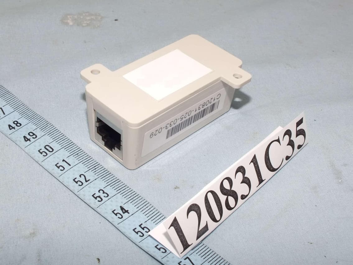
Click to zoom
Application Details
- Equipment Class
- DTS - Digital Transmission System
- Date of Grant
- Nov 28, 2012
- Application Purpose
- Original Equipment
- Date of Application
- Nov 28, 2012
- Equipment Note
- Secured Wireless Access Point
- Frequency Range
- 2412.00000000 - 2462.00000000
- Company
- EnGenius Technologies
- Country
- United States
Documents & Files
Document Text
Text extracted from the exhibit documents filed with the FCC. Open a document above to read the original.
Users Manual
EnGenius ® X-TRA RANGE ® ENS200 LONG RANGE WIRELESS 11N OUTDOOR CB / AP User Guide V1.0 TABLE OF CONTENTS I TABLE OF CONTENTS Conventions0-vi Copyright0-viii Product Overview Package Contents1-1 Product Overview1-2 Key Features . . . . . . . . . . . . . . . . . . . . . . . . . . . . . . . . . . . . . . . . . . . . . . . . . . . . . . .1-2 Benefits . . . . . . . . . . . . . . . . . . . . . . . . . . . . . . . . . . . . . . . . . . . . . . . . . . . . . . . . . . .1-3 Technical Specification . . . . . . . . . . . . . . . . . . . . . . . . . . . . . . . . . . . . . . . . . . . . . . . . .1-4 Physical Interface . . . . . . . . . . . . . . . . . . . . . . . . . . . . . . . . . . . . . . . . . . . . . . . . . . .1-4 Wireless Specification . . . . . . . . . . . . . . . . . . . . . . . . . . . . . . . . . . . . . . . . . . . . . . . .1-4 Hardware Specification . . . . . . . . . . . . . . . . . . . . . . . . . . . . . . . . . . . . . . . . . . . . . . .1-4 Product Layout1-5 Installation System Requirements2-1 TABLE OF CONTENTS II Installing the Device2-2 Pre-Installation Guidelines . . . . . . . . . . . . . . . . . . . . . . . . . . . . . . . . . . . . . . . . . . . . . .2-2 Installing the Device . . . . . . . . . . . . . . . . . . . . . . . . . . . . . . . . . . . . . . . . . . . . . . . . . .2-2 Web Configuration Logging In3-1 Best Practices . . . . . . . . . . . . . . . . . . . . . . . . . . . . . . . . . . . . . . . . . . . . . . . . . . . . . . .3-2 Basic Network Settings System Status4-1 Using Save/Load4-1 Viewing System Information4-2 Viewing Wireless Client List4-4 Viewing System Log4-5 Viewing Connection Status4-6 Viewing DHCP Client Table4-7 Viewing WDS Link List4-8 System Setup4-9 Configuring Operation Mode4-9 TABLE OF CONTENTS III Configuring IP Settings4-10 Configuring Spanning Tree Settings4-11 Router Setup4-12 Configuring WAN Settings4-12 Static IP . . . . . . . . . . . . . . . . . . . . . . . . . . . . . . . . . . . . . . . . . . . . . . . . . . . . . . . . . . 4-12 Dynamic IP. . . . . . . . . . . . . . . . . . . . . . . . . . . . . . . . . . . . . . . . . . . . . . . . . . . . . . . . 4-13 Point-to-Point Protocol over Ethernet (PPPoE) . . . . . . . . . . . . . . . . . . . . . . . . . . . . . . . . 4-14 Point-to-Point Tunnelling Protocol (PPTP) . . . . . . . . . . . . . . . . . . . . . . . . . . . . . . . . . . . 4-16 Configuring LAN Settings4-18 Configuring VPN Pass-Through4-19 Configuring Port Forwarding4-20 Configuring Demilitarized Zone4-22 Configuring Wireless LAN4-23 Configuring Wireless Settings4-23 Access Point Mode . . . . . . . . . . . . . . . . . . . . . . . . . . . . . . . . . . . . . . . . . . . . . . . . . . . 4-23 Client Bridge Mode . . . . . . . . . . . . . . . . . . . . . . . . . . . . . . . . . . . . . . . . . . . . . . . . . . 4-26 WDS Bridge Mode . . . . . . . . . . . . . . . . . . . . . . . . . . . . . . . . . . . . . . . . . . . . . . . . . . . 4-27 Client Router Mode . . . . . . . . . . . . . . . . . . . . . . . . . . . . . . . . . . . . . . . . . . . . . . . . . . 4-28 Configuring Wireless Security4-29 Wired Equivalent Privacy (WEP) . . . . . . . . . . . . . . . . . . . . . . . . . . . . . . . . . . . . . . . . . 4-29 TABLE OF CONTENTS IV Wi-Fi Protected Access Pre-Shared Key (WPA-PSK) . . . . . . . . . . . . . . . . . . . . . . . . . . . . 4-30 Wi-Fi Protected Access 2 Pre-Shared Key (WPA2-PSK). . . . . . . . . . . . . . . . . . . . . . . . . . 4-31 Wi-Fi Protected Access Pre-Shared Key (WPA-PSK) Mixed . . . . . . . . . . . . . . . . . . . . . . . 4-32 Wi-Fi Protected Access (WPA) . . . . . . . . . . . . . . . . . . . . . . . . . . . . . . . . . . . . . . . . . . . 4-33 Wi-Fi Protected Access 2 (WPA2) . . . . . . . . . . . . . . . . . . . . . . . . . . . . . . . . . . . . . . . . 4-35 Wi-Fi Protected Access (WPA) Mixed . . . . . . . . . . . . . . . . . . . . . . . . . . . . . . . . . . . . . . 4-37 Configuring Wireless MAC Filter4-39 Configuring WDS Link Settings4-40 Configuring Advanced Network Settings4-41 Management Setup4-43 Configuring Administrator Account4-43 Configuring Management VLAN4-45 Configuring SNMP4-46 Configuring Backup/Restore Settings4-48 Configuring Firmware Upgrade4-49 Configuring System Time4-50 Configuring Command Line Interface4-51 Configuring Logging4-52 Configuring Diagnostics4-53 Viewing Device Discovery4-54 TABLE OF CONTENTS V Configure Denial of Service Protection4-55 Logging Out4-56 Appendix A Federal Communication Commission Interference StatementA-1 Appendix B Industry Canada StatementB-1 Appendix C WorldWide Technical SupportC-1 CONVENTIONS 0-VI Conventions The following conventions are used to give the user additional information about specific procedures or content. It is important to pay attention to these conventions as they provide informa- tion to prevent damage to equipment or personal injury. General Conventions The following general conventions are used in this document. N/A: Indicates that a component or a procedure is not applica- ble to this model. Prerequisite: Indicates a requirement that must be addressed before proceeding with the current function or procedure. CAUTION! CAUTIONS APPEAR BEFORE THE TEXT IT REFERENCES. CAU- TIONS APPEAR IN CAPITAL LETTERS TO EMPHASIZE THAT THE MESSAGE CONTAINS VITAL HEALTH AND SAFETY INFORMATION. WARNING! Warning information appears before the text it references to emphasize that the content may prevent damage to the device or equipment. Important: Indicates information that is important to know for the proper completion of a procedure, choice of an option, or completing a task. Note: Indicates additional information that is relevant to the cur- rent process or procedure. ! ! Example: Indicates information used to demonstrate or explain an associated concept. CONVENTIONS 0-VII Typographical Conventions The following typographical conventions are used in this docu- ment: Italics Indicates book titles, directory names, file names, path names, and program/process names. Constant w…
Text truncated - open the document above for the full version.
Users Manual
BASIC NETWORK SETTINGSCONFIGURING IP SETTINGS 4-10 4.2.2 Configuring IP Settings Configure the LAN settings for the ENS200 using a static or dynamic IP address. IP Network Setting Configure the network connection type using either a static IP or dynamic IP. IP Address Enter the LAN IP address of the ENS200. Subnet Mask Enter the subnet mask of the ENS200. Default Gateway Enter the default gateway of the ENS200. Primary DNS Enter the primary DNS address of the ENS200. Secondary DNS Enter the secondary DNS address of the ENS200. Click Apply to save the settings or Cancel to discard changes. BASIC NETWORK SETTINGSCONFIGURING SPANNING TREE SETTINGS 4-11 4.2.3 Configuring Spanning Tree Settings Spanning Tree Status Enable or disable the ENS200 Spanning Tree function. Bridge Hello Time Specify Bridge Hello Time, in seconds. This value determines how often the ENS200 sends hello packets to communicate information about the topology throughout the entire Bridged Local Area Network Bridge Max Age Specify Bridge Max Age, in seconds. If another bridge in the spanning tree does not send a hello packet for a long period of time, it is assumed to be dead. Bridge Forward Delay Specify Bridge Forward Delay, in seconds. Forwarding delay time is the time spent in each of the Listening and Learning states before the Forwarding state is entered. This delay is provided so that when a new bridge comes onto a busy network, it looks at some traffic before participating. Priority Specify the Priority number. Smaller numbers have greater priority. Click Accept to confirm the changes or Cancel to cancel and return previous settings. BASIC NETWORK SETTINGSROUTER SETUP 4-12 4.3 Router Setup 4.3.1 Configuring WAN Settings Configure the WAN settings for the ENS200 using a static or dynamic IP address, PPPoE or PPTP. Static IP Setting a static IP address allows an administrator to set a specific IP address for the router and guarantees that it can not be assigned a different address. Account Name Enter the account name provided by your ISP Domain Name Enter the domain name provided by your ISP MTU The maximum transmission unit (MTU) specifies the largest packet size permitted for an internet transmission. The factory default MTU size for static IP is 1500. The MTU size can be set between 512 and 1500. IP Address Enter the router’s WAN IP address. Subnet Mask Enter the router’s WAN subnet mask. Default Gateway Enter the WAN gateway address. Primary DNS Enter the primary DNS server address. Secondary DNS Enter the secondary DNS server address. Discard Ping on WAN Check to Enable to recognize pings on the ENS200 WAN interface or Disable to block pings on the BASIC NETWORK SETTINGSDYNAMIC IP 4-13 ENS200 WAN interface. Note: Pinging IP addresses is a common method used by hackers to test whether the IP address is valid. Blocking pings provides some extra security from hackers. Click Accept to save the settings or Cancel to discard changes. Dynamic IP Dynamic IP addressing assigns a different IP address each time a device connects to an ISP service provider. The service is most commonly used by ISP cable providers. Account Name Enter the account name provided by your ISP Domain Name Enter the domain name provided by your ISP MTU The maximum transmission unit (MTU) specifies the largest packet size permitted for an internet transmission. The factory default MTU size for static IP is 1500. The MTU size can be set between 512 and 1500. Get Automatically From ISP Click the radio button to obtain the DNS automatically from the DHCP server. Use These DNS Servers Click the radio button to set up the Primary DNS and Secondary DNS servers manually. Discard Ping on WAN Check to Enable to recognize pings on the ENS200 WAN interface or Disable to block pings on the ENS200 WAN interface. Note: Pinging IP addresses is a common method used by hackers to test whether the IP address is valid. Blocking pings provides some extra security from hackers. Click Accept to save the settings or Cancel to discard changes. BASIC NETWORK SETTINGSPOINT-TO-POINT PROTOCOL OVER ETHERNET (PPPOE) 4-14 Point-to-Point Protocol over Ethernet (PPPoE) Point-to-Point Protocol over Ethernet (PPPoE) is used mainly by ISPs that provide DSL modems to connect to the Internet. MTU Enter the maximum transmission unit (MTU). The MTU specifies the largest packet size permitted for an internet transmission (PPPoE default: 1492). The MTU size can be set between 512 and 1492. Login Enter the username assigned by an ISP. Password Enter the password assigned by an ISP. Service Name Enter the service name of an ISP (optional). Connect on Demand Select the radio button to specify the maximum idle time. Internet connection will disconnect when it reach the maximum idle time, but it will automatically connect when user tries to access the network. Keep Alive Select whether to keep the Internet connection always on, or enter a redial period once the internet lose connection. BASIC NETWORK SETTINGSPOINT-TO-POINT PROTOCOL OVER ETHERNET (PPPOE) 4-15 Get Automatically From ISP Click the radio button to obtain the DNS automatically from the DHCP server. Use These DNS Servers Click the radio button to set up the Primary DNS and Secondary DNS servers manually. Discard Ping on WAN Check to Enable to recognize pings on the ENS200 WAN interface or Disable to block pings on the ENS200 WAN interface. Note: Pinging IP addresses is a common method used by hackers to test whether the IP address is valid. Blocking pings provides some extra security from hackers. Click Accept to save the settings or Cancel to discard changes. BASIC NETWORK SETTINGSPOINT-TO-POINT TUNNELLING PROTOCOL (PPTP) 4-16 Point-to-Point Tunnelling Protocol (PPTP) The point-to-point tunnelling protocol (PPTP) is used in association with virtual private networks (VPNs). There a two parts to a PPTP connection: the WAN interface settings and the PPTP settings. MTU Enter the maximum transmission unit (MTU). The MTU specifies the larg…
Text truncated - open the document above for the full version.
Users Manual
1 Wireless-N 150Mbps Long Range Wall Mount AP/Repeate r ERA150 Wireless-N 150Mbps Long Range Wall Mount AP/Repeat er V1.0 1 Table of Contents 1 Introduction ...................................... ................................................... ................................................... ........................... 5 1.1 Features and Benefits ............................... ................................................... ................................................... ................................................ 6 1.2 Package Contents .................................... ................................................... ................................................... .................................................. 7 1.3 System Requirements ................................. ................................................... ................................................... .............................................. 7 1.4 Applications ....................................... ................................................... ................................................... ................................................... ....... 7 2 Before you Begin .................................. ................................................... ................................................... ....................... 9 2.1 Considerations for Wireless Installation ............. ................................................... ................................................... ............................... 9 2.2 Computer Settings (Windows XP/Windows 7) ............. ................................................... ................................................... ................ 10 2.3 Computer Settings in Apple Mac X OS .................. ................................................... ................................................... ......................... 13 2.4 Hardware Installation ............................... ................................................... ................................................... .............................................. 14 3 Configuring Your Access Point ..................... ................................................... ................................................... ........... 17 3.1 Default Settings .................................... ................................................... ................................................... ................................................... 17 3.2 Web Configuration .................................. ................................................... ................................................... ............................................... 18 4 Building a Wireless Network ....................... ................................................... ................................................... ............ 20 4.1 Access Point Mode .................................. ................................................... ................................................... ............................................... 20 4.2 Repeater mode ...................................... ................................................... ................................................... .................................................. 21 5 Status ............................................ ................................................... ................................................... .............................. 22 5.1 Save/Reload ....................................... ................................................... ................................................... ................................................... .... 22 5.2 Main .............................................. ................................................... ................................................... ................................................... ............ 23 5.3 Wireless Client List ............................... ................................................... ................................................... ................................................... 25 5.4 Connection Status .................................... ................................................... ................................................... ............................................... 26 5.5 System Log ......................................... ................................................... ................................................... ................................................... .... 27 6 System ............................................ ................................................... ................................................... ............................ 28 2 6.1 Operation Mode ..................................... ................................................... ................................................... ................................................. 2 8 6.2 IP Settings ......................................... ................................................... ................................................... ................................................... ...... 29 6.3 Spanning Tree Setting ............................... ................................................... ................................................... ............................................ 30 7 Wireless .......................................... ................................................... ................................................... ............................ 31 7.1 Wireless Network ................................... ................................................... ................................................... ................................................. 3 1 7.2 Wireless Security .................................. ...........................................…
Text truncated - open the document above for the full version.
Users Manual
FortiAP 112B QuickStart Guide September 14, 2012 20-430-177873-20120914 Copyright© 2012 Fortinet, Inc. All rights reserved. Fortinet®, FortiGate®, and FortiGuard®, are registered trademarks of Fortinet, Inc., and other Fortinet names herein may also be trademarks of Fortinet. All other product or company names may be trademarks of their respective owners. Performance metrics contained herein were attained in internal lab tests under ideal conditions, and performance may vary. Network variables, different network environments and other conditions may affect performance results. Nothing herein represents any binding commitment by Fortinet, and Fortinet disclaims all warranties, whether express or implied, except to the extent Fortinet enters a binding written contract, signed by Fortinet’s General Counsel, with a purchaser that expressly warrants that the identified product will perform according to the performance metrics herein. For absolute clarity, any such warranty will be limited to performance in the same ideal conditions as in Fortinet’s internal lab tests. Fortinet disclaims in full any guarantees. Fortinet reserves the right to change, modify, transfer, or otherwise revise this publication without notice, and the most current version of the publication shall be applicable. Table of Contents Package Contents 1 Connecting Your FortiAP Unit 2 Access Point Configuration 3 Mesh Mode Configuration 5 Mounting Your FortiAP Unit 7 Technical Specifications 9 LED Specifications 10 Documentation and Links 11 Cautions and Warnings 12 Register Your Product 14 Product License Agreement 15 Package Contents Page 1 Fortinet’s FortiAP wireless thin access points deliver secure, identity-driven WiFi client access that creates a fortified WLAN network that is centrally managed by a FortiGate or FortiWiFi platform. The FortiAP 112B has built-in proprietary PoE to support long-range network installation. It can be setup either as an access point, or in mesh mode. Your box contains the following: FortiAP 112B QuickStart Guide Wall/Pole Mounting Hardware Kit PoE Injector with Power Adapter FortiAP 112B QuickStart Guide Quickstart Guide Wall/Pole Mounting Hardware Kit L AN P o E PoE InjectorPower Adapter Page 2 Connecting Your FortiAP Unit The FortiAP 112B -PoE can be configured to function as an access point, or to operate in mesh mode. Adequate grounding must be provided to the FortiAP unit and the PoE injector, in compliance with the local electrical code. Note: The included PoE injector must be mounted indoors, as it is not weatherproof. Caution: Only use the provided PoE injector (EPE-1212) and power adapter with this devices. Using a different PoE injector or power adapter may cause damage to the device. Note: The FortiAP 112B has a directional antenna located on the front of the device. For a reliable wireless connection, the device must be aimed towards its target to establish a connection. See Mounting Your FortiAP Unit on page 7. To connect the FortiAP unit: 1. Insert an Ethernet cable into the ETH (PoE) port of the FortiAP unit and insert the other end of the cable into the PoE port on the provided PoE injector. 2. Insert one end of the provided power adapter into the PoE injector, and plug the other end into an electrical outlet. The Status LED will light up. 3. Insert an Ethernet cable from the LAN port of the provided PoE injector or the ETH port of the FortiAP unit, to a PC, FortiGate, or FortiWifi device. To configure the management computer: 1. Configure the management computer to be on the same subnet as the internal interface of the FortiAP unit: a. Browse to the Network and Sharing Center > Change Adapter Settings > Local Area Connection Properties > Internet Protocol Version 4 (TCP/IPv4) Properties. b. Change the IP address of the management computer to 192.168.1.1 and the netmask to 255.255.255.0. 2. Connect from the LAN port of the PoE injector, or the ETH port on the FortiAP unit, to the management computer using an Ethernet cable. Page 3 The FortiAP unit is designed to require no configuration in most networks. Zero Configuration mode works if the unit is directly connected (or through the PoE injector) to the FortiGate or FortiWifi performing the Wireless LAN Controller (WLC) functions, or on the same layer-2 network and subnet as the FortiGate or FortiWifi unit. If the FortiAP wireless controller’s IP address cannot be determined using Zero Configuration mode, or if the network uses static IP addresses, it can be configured to use a static IP address. To enable the FortiAP using Zero Configuration: 1. After connecting the FortiAP unit as described in the previous chapter, the unit goes through its boot procedure and requests an IP address from the DHCP server. 2. If the IP address is retrieved successfully, the FortiAP enters discovery mode to locate a FortiGate or FortiWifi wireless controller. The discovery modes are: • Broadcast • Multicast • DHCP option 138 3. Verify that the FortiAP has successfully connected to the controller. In the FortiGate Web-based Manager, go to WiFi Controller > Managed Access Points > Managed FortiAP. A successfully discovered unit displays an orange circle with a question mark. 4. Select the access point and click Edit. 5. In the State field, select Authorize. 6. In the AP Profile field, select Change, then select a profile from the list and click OK. The configuration is downloaded from the wireless controller to the FortiAP and the WiFi LED lights up. To enable the FortiAP with a static IP address: 1. Connect the unit and configure the management computer as described in the “Connecting Your FortiAP Unit” chapter. 2. Telnet to IP address 192.168.1.2. 3. Type admin in the Name field, leave the Password field blank, and press Enter. Access Point Configuration 4. Configure a static IP address for the FortiAP unit and netmask & gateway information for your network, using the following commands: cfg -a ADDR_MODE=STATIC cfg –a AP_IPADDR=xxx.xxx.xxx.xx…
Text truncated - open the document above for the full version.
External Photos
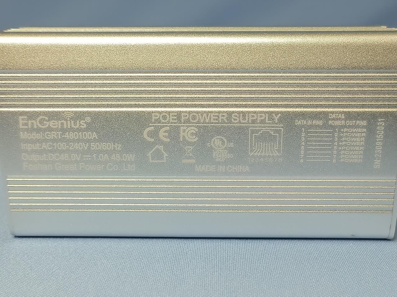
Page 1 CONSTRUCTION PHOTOS OF EUT MODEL: ERA150 Page 2 Page 3 Page 4 Page 5 MODEL: DSA‐12G‐12 FUS 120120 (Adapter) Page 6 Page 7 MODEL: ENS200 Page 8 Page 9 MODEL: FAP‐112B Page 10 Page 11 Model: EPE‐1212 (POE) Page 12 MODEL: DSA‐12G‐12 FUS 120120 (Adapter for POE) Page 13 Page 14 MODEL: PA1024‐2HUB (Adapter for POE) Page 15
ID Label/Location Info
FCC ID:A8J-ENS200 IC: 10103A-ENS200 FCC ID:A8J-ENS200 IC: 10103A-ENS200
Internal Photos
Page 16 MODEL: ERA150 Page 17 Page 18 Page 19 Page 20 MODEL: ENS200 Page 21 Page 22 Page 23 Page 24 Page 25 Page 26 MODEL: FAP‐112B Page 27 Page 28 Page 29 Page 30 Page 31
Operational Description
FCC ID: A8J-ENS200 Report No.: RF120831C35 Operational Description This device is a Secured Wireless Access Point, which operates in 2.4GHz band; the maximum data rate could be up to 300Mbps which OFDM technique. If the signal to noise radio is too poor which could not support 150Mbps, the 11Mbps data rate with DSSS technique will be applied. The transmitter of the EUT is powered by the 48Vdc or 12Vdc from POE or 5Vdc from power adapter. The EUT is used antenna list as below: The other instruction, please have a look at the users manual.
RF Exposure Info
Report No.: SA120831C35 of 5 Report Format Version 5.0.0 1 RF EXPOSURE REPORT REPORT NO.: SA120831C35 MODEL NO.: ERA150, ENS200, FAP-112B FCC ID: A8J-ENS200 RECEIVED: Sep. 02, 2012 TESTED: Sep. 05 ~ Sep. 19, 2012 ISSUED: Sep. 21, 2012 APPLICANT: EnGenius Technologies ADDRESS: 1580 Scenic Avenue, Costa Mesa, CA92626 ISSUED BY: Bureau Veritas Consumer Products Services (H.K.) Ltd., Taoyuan Branch LAB ADDRESS: No. 47, 14th Ling, Chia Pau Vil., Lin Kou Dist., New Taipei City, Taiwan, R.O.C. TEST LOCATION: No. 19, Hwa Ya 2nd Rd, Wen Hwa Tsuen, Kwei Shan Hsiang, Taoyuan Hsien 333, Taiwan, R.O.C. This report is for your exclusive use. Any copying or replication of this report to or for any other person or entity, or use of our name or trademark, is permitted only with our prior written permission. This report sets forth our findings solely with respect to the test samples identified herein. The results set forth in this report are not indicative or representative of the quality or characteristics of the lot from which a test sample was taken or any similar or identical product unless specifically and expressly noted. Our report includes all of the tests requested by you and the results thereof based upon the information that you provided to us. You have 60 days from date of issuance of this report to notify us of any material error or omission caused by our negligence, provided, however, that such notice shall be in writing and shall specifically address the issue you wish to raise. A failure to raise such issue within the prescribed time shall constitute your unqualified acceptance of the completeness of this report, the tests conducted and the correctness of the report contents. Unless specific mention, the uncertainty of measurement has been explicitly taken into account to declare the compliance or non-com pliance to the specification. Report No.: SA120831C35 of 5 Report Format Version 5.0.0 2 TABLE OF CONTENTS RELEASE CONTROL RECORD ................................................................................................................ 3 1. CERTIFICATION ............................................................................................................................. 4 2. RF EXPOSURE ............................................................................................................................... 5 2.1 LIMITS FOR MAXIMUM PERMISSIBLE EXPOSURE (MPE) ........................................................ 5 2.2 MPE CALCULATION FORMULA .................................................................................................... 5 2.3 CLASSIFICATION ........................................................................................................................... 5 2.4 CALCULATION RESULT OF MAXIMUM CONDUCTED POWER ................................................. 5 Report No.: SA120831C35 of 5 Report Format Version 5.0.0 3 RELEASE CONTROL RECORD ISSUE NO. REASON FOR CHANGE DATE ISSUED SA120831C35 Original release Sep. 21, 2012 Report No.: SA120831C35 of 5 Report Format Version 5.0.0 4 1. CERTIFICATION PRODUCT: Secured Wireless Access Point MODEL: ERA150, ENS200, FAP-112B BRAND: EnGenius, Fortinet APPLICANT: EnGenius Technologies TESTED: Sep. 06 ~ Sep. 15, 2012 TEST SAMPLE: ENGINEERING SAMPLE STANDARDS: FCC Part 2 (Section 2.1091) FCC OET Bulletin 65, Supplement C (01-01) IEEE C95.1 The above equipment (Model: ERA150, ENS200) has been tested by Bureau Veritas Consumer Products Services (H.K.) Ltd., Taoyuan Branch, and found compliance with the requirement of the above standards. The test record, data evaluation & Equipment Under Test (EUT) configurations represented herein are true and accurate accounts of the measurements of the sample’s EMC characteristics under the conditions specified in this report. PREPARED BY : , DATE :Sep. 21, 2012 Pettie Chen / Senior Specialist APPROVED BY : , DATE :Sep. 21, 2012 Gary Chang / Technical Manager Report No.: SA120831C35 of 5 Report Format Version 5.0.0 5 2. RF EXPOSURE 2.1 LIMITS FOR MAXIMUM PERMISSIBLE EXPOSURE (MPE) FREQUENCY RANGE (MHz) ELECTRIC FIELD STRENGTH (V/m) MAGNETIC FIELD STRENGTH (A/m) POWER DENSITY (mW/cm 2 ) AVERAGE TIME (minutes) LIMITS FOR GENERAL POPULATION / UNCONTROLLED EXPOSURE 300-1500 ... ... F/1500 30 1500-100,000 ... ... 1.0 30 F = Frequency in MHz 2.2 MPE CALCULATION FORMULA Pd = (Pout*G) / (4*pi*r 2 ) where Pd = power density in mW/cm 2 Pout = output power to antenna in mW G = gain of antenna in linear scale Pi = 3.1416 R = distance between observation point and center of the radiator in cm 2.3 CLASSIFICATION The antenna of this product, under normal use condition, is at least 20cm away from the body of the user. So, this device is classified as Mobile Device. 2.4 CALCULATION RESULT OF MAXIMUM CONDUCTED POWER MAX POWER (dBm) ANTENNA GAIN (dBi) DISTANCE (cm) POWER DENSITY (mW/cm 2 ) LIMIT (mW/…
Text truncated - open the document above for the full version.
Contact Information
Applicant
Mingi Tsai(Senior Product Manager)
Test Firm
Bureau Veritas CPS (H.K.) Ltd., Taoyuan BranchRichard Chen
Technical Specifications
| # | Rule Parts | Frequency Range | Power Output |
|---|---|---|---|
| 1 | 15C | 2.41 GHz - 2.46 GHz | 245.00 mW |
Other Applications from EnGenius Technologies
A8J-EOC655
Feb 18, 2024Outdoor6 2x2 CPE
Equipment Class
DTS - Digital Transmission System
A8J-ENSTATION6
May 07, 2023EnGenius Station Wi-Fi 6 2x2 5GHz Outdoor CPE
Equipment Class
DTS - Digital Transmission System
A8J-ECW270
Mar 21, 2023Cloud6 4x4 Outdoor
Equipment Class
DTS - Digital Transmission System
A8J-ECW230S
Jul 31, 202211ax Cloud Managed AP
Equipment Class
NII - Unlicensed National Information Infrastructure TX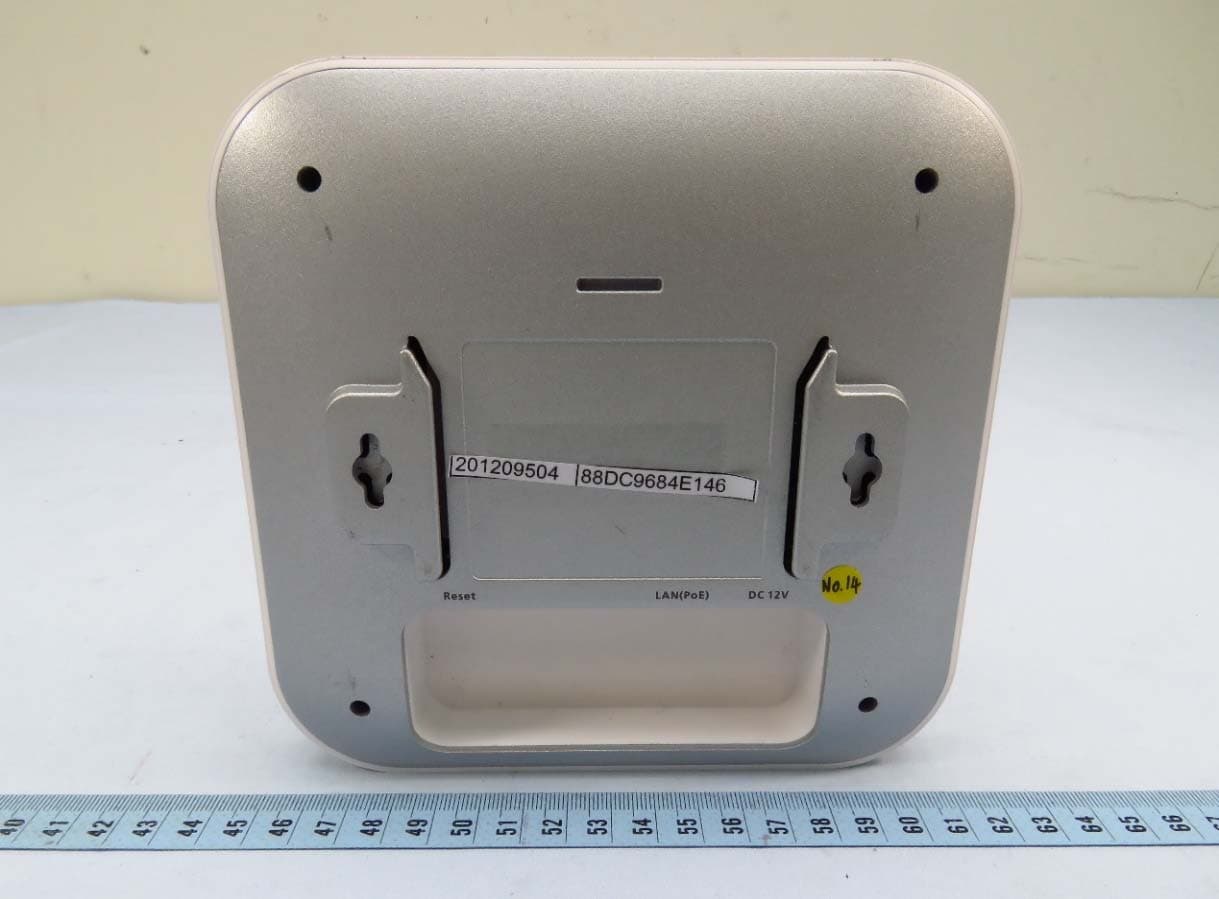
A8J-EWS357APV3A
Jan 17, 202111ax Indoor Managed AP, 11ax Cloud Managed AP
Equipment Class
DTS - Digital Transmission System