A95-TURNON01Remote Control
Dukane CorporationApplication Details
- Equipment Class
- DSC - Part 15 Security/Remote Control Transmitter
- Date of Grant
- Jul 06, 2004
- Application Purpose
- Original Equipment
- Date of Application
- Jul 06, 2004
- Equipment Note
- Remote Control
- Frequency Range
- 433.92000000 - 433.92000000
- Company
- Dukane Corporation
- Country
- United States
Documents & Files
Document Text
Text extracted from the exhibit documents filed with the FCC. Open a document above to read the original.
Users Manual
12 VOLT AUTOMOTIVE CONTROL SYSTEM Thank you for purchasing the 2KOOL automotive 12 Volt control system. This is the most advanced program- mable control system available today. This system can control interior and exterior neon, strobe, and LED lights, EL logos, and customized functions. With an optional relay and receiver applications such as trunk lids, shaved door handles and linear actuators can be controlled. Consult with a professional installer when current requirements for your application exceed 10 Amps. THE 2KOOL SYSTEM The 2KOOL System (patent pending) has two components: a keypad that is used to send the activation com- mand, and a receiver that responds to the commands by turning the application on and off. KEYPAD The keypad has five buttons. Four can be used to send individual on/off commands, and one sends an off command to all trained receivers. RECEIVER The receiver, when trained, is used to turn your applications on and off. After training, the receiver will only respond to pressing the button you select. Each receiver has a different code so you don’t have to worry about interfering with another 2KOOL control system. CAUTION Please follow manufacturer’s installation recommendations when adding accessory items, particularly auxiliary lighting. Lights installed with a 2Kool controller may be intended for off-road or show use only. Check with your light manufacturer and local authorities before street use. Installation of any merchandise shall be the sole and absolute responsibility of the purchaser. See our web site at www.2kooltech.com or call 1-877-UR2KOOL (1-877-872-5665) for complete details. SPECIFICATIONS KEYPAD 5 control buttons-4 for on/off and 1 for all off. Self contained replaceable battery. FCC approved (no license is necessary). RECEIVER User programmable for the desired keypad button location. Power input and output is +12 Volts and ground. The wire with the white stripe is + 12 Volts. Note: Applications over 1 Amp require a relay. Figure 1 Receiver Training Perform the following steps to train the receiver after it has been wired to the accessory and to a 12 Volt power source. 1. Remove the two phillips head screws and remove the cover from the receiver housing. 2. Locate the small jumper block shown in Figure 3 below. Gently pull up on the jumper block that is pressed onto one of the pins. Lift it off of the single pin, reposition it over both pins and gently press it down. It is now in the training mode. 3. Press the keypad button you wish to use several times. (You will see the light or accessory turn on and off) and replace the jumper so that it only covers one pin. 4.Replace the cover on the receiver. The receiver will now respond to the button you pressed. Note: When the jumper covers both pins (training mode) the receiver will respond to any button you press. The receiver only remembers the last button you press as its assigned button. NOTE The range of the keypad can be affected by where you put the receiver in the car. If you are having trouble activating the receiver with the keypad, move the receiver to another location. See the FAQ section of the 2Kool website for more installation information. 2Kool Technologies St. Charles, IL 60174 www.2kooltech.com Compliance Statement ( Part 15.19 ) This device complies with Part 15 of the FCC Rules and with RSS-210 of Industry Canada. Operation is subject to the following two conditions: 1. This device may not cause harmful interference, and 2. This device must accept any interference received, including interference that may cause undesired operation. Warning ( Part 15.21 ) Changes or modifications not expressly approved by the party responsible for compliance could void the user’s authority to operate the equipment. CONNECTION Select the physical location of your application such as neon lights. Install the lights in accordance with the manufacturer recommendations. Connect the wire from the lights to the receiver wire. This is the wire on the right hand side (see figure 2). The wire with the white stripe is the ( + ) wire the other wire is the ground wire. For power connect the wire coming from the left hand side of the receiver to a 12 Volt source and ground. The wire with the white stripe is +12 Volts, the other wire is connected to ground. Note: When mounting receiver unit make sure you have access to the two phillips head screws on the cover plate. You will need to remove the cover to train the receiver. Figure 2 PATENT PENDING Figure 3 Typical Lights/Accessories Connection Typical Underbody Light Connection (Over 1 Amp Application) *Most Underbody Kits Exceed 1 Amp
Cover Letter(s)
F C C CONFIDENTIALITY Date: 5/18/04 To: FEDERAL COMMUNICATIONS COMMISSION 7435 Oakland Mills Road Columbia, MD 21046 Subject: Request for Non disclosure for FCC ID: A95-TurnOn01 To Whom It May Concern: Pursuant to 47 CFR Section 0.459, Dukane Corporation hereby requests non disclosure and confidential treatment of the following materials submitted in support of FCC certification application for FCC ID # A95-TurnOn01 a. Schematic Diagrams b. Operational Description c. Block Diagram Above materials contain trade secrets, proprietary and technical information which would customarily be guarded from competitors under 47 CFR section 0.457(d)(2). Disclosure or publication of any portion of this company confidential material to other parties could cause substantial competitive harm and provide unjustified benefits for competitors. Dukane Corporation understands that pursuant to 47 CFR section 0.457(d)(1)(ii) disclosure of the applicant and all accompanying documentation will not be made before the date of the grant. Sincerely yours, Kenneth D. Neltnor / Director of Engineering Dukane Corporation Seacom Dukane Corporation Seacom Division 2900 Dukane Drive St. Charles, IL 60174 TEL: (630) 762-4050 FAX: (630) 762-4049 WEB: www.dukcorp.com/sc E-mail: [email protected]
External Photos
Dukane Corporation 2KOOL Automotive Control System Turn On Key Fob FCC ID#: A95-TURNON01 Photo One – External Top View of Transmitter – 5 Key Control Dukane Corporation 2KOOL Automotive Control System Turn On Key Fob FCC ID#: A95-TURNON01 Photo Two – External Back View of Transmitter – FCC ID Label Dukane Corporation 2KOOL Automotive Control System Turn On Key Fob FCC ID#: A95-TURNON01 Photo Three – External Close-Up of FCC ID Label
ID Label/Location Info
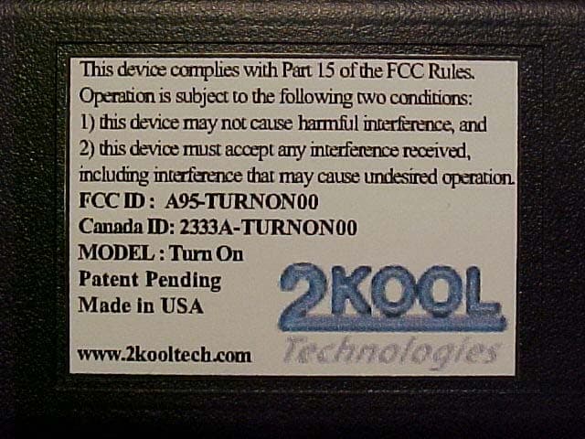
FCC ID : A95-TURNON01 Canada ID: 2333A-TURNON01 MODEL : Turn On Patent Pending Made in USA www.2kooltech.com
Internal Photos
Dukane Corporation 2KOOL Automotive Control System Turn On Key Fob FCC ID#: A95-TURNON01 Photo One - Internal Open for Inspection Dukane Corporation 2KOOL Automotive Control System Turn On Key Fob FCC ID#: A95-TURNON01 Photo Two - Internal Close-up of RF Section and PCB Antenna Dukane Corporation 2KOOL Automotive Control System Turn On Key Fob FCC ID#: A95-TURNON01 Photo Three - Internal Flip side of PCB – Antenna on Top Dukane Corporation 2KOOL Automotive Control System Turn On Key Fob FCC ID#: A95-TURNON01 Photo Four - Internal Components of the Key Fob
Test Report
Test Report #: 304223 Page 1 of 23 Prepared For: Dukane Corporation Prepared By: L.S. Compliance, Inc. L.S. Compliance, Inc. W66 N220 Commerce Court Cedarburg, WI 53012 262.375.4400 FAX: 262.375.4248 Compliance Testing of: “Turn On” Key-FOB Transmitter Prepared For: Dukane Corporation Attention: Mr. Dan Kramer 2900 Dukane Drive St. Charles, IL 60174 Test Report Number: 304223 Test Date(s): May 24 th , 2004 All results of this report relate only to the items that were tested. This report may not be reproduced, except in full, without written approval of L.S. Compliance, Inc. Test Report #: 304223 Page 2 of 23 Prepared For: Dukane Corporation Prepared By: L.S. Compliance, Inc. Table of Contents Section Description Page Index 2 1 L.S. Compliance in Review 3 2 A2LA Certificate of Accreditation 4 3 A2LA Scope of Accreditation 5 4 Validation Letter-U.S. Competent Body for EMC Directive 89/336/EEC 6 5 Signature Page 7 6 Product and General Information 8 7 Introduction 8 8 Product Description 8 9 Test Requirements 9 10 Summary of Test Report 9 11 Radiated Emissions Test 10-18 12 Conducted Emissions Test (AC Line) 19 Appendices A Calculations 20 B Duty Cycle Correction 21-22 C Test Equipment List 23 Test Report #: 304223 Page 3 of 23 Prepared For: Dukane Corporation Prepared By: L.S. Compliance, Inc. 1. L.S. Compliance in Review L.S. Compliance - Accreditations and Listing’s As an EMC Testing Laboratory, our Accreditation and Assessments are recognized through the following: A2LA – American Association for Laboratory Accreditation Accreditation based on ISO/IEC 17025 : 1999 with Electrical (EMC) Scope of Accreditation A2LA Certificate Number: 1255.01 Federal Communications Commission (FCC) – USA Listing of 3 Meter Semi-Anechoic Chamber based on Title 47 CFR – Part 2.948 FCC Registration Number: 90756 Listing of 3 and 10 meter OATS based on Title 47CFR – Part 2.948 FCC Registration Number: 90757 Industry Canada On file, 3 Meter Semi-Anechoic Chamber based on RSS-212 – Issue 1 File Number: IC 3088-A On file, 3 and 10 Meter OATS based on RSS-212 – Issue 1 File Number: IC 3088 U. S. Conformity Assessment Body (CAB) Validation Validated by the European Commission as a U. S. Competent Body operating under the U. S. /EU, Mutual Recognition Agreement (MRA) operating under the European Union Electromagnetic Compatibility –Council Directive 89/336/EEC, Article 10.2. Date of Validation: January 16, 2001 Validated by the European Commission as a U.S. Notified Body operating under the U.S./EU, Mutual Recognition Agreement (MRA) operating under the European Union Telecommunication Equipment – Council Directive 99/5/EC, Annex V. Date of Validation: November 20, 2002 Notified Body Identification Number: 1243 Test Report #: 304223 Page 4 of 23 Prepared For: Dukane Corporation Prepared By: L.S. Compliance, Inc. 2. A2LA Certificate of Accreditation Test Report #: 304223 Page 5 of 23 Prepared For: Dukane Corporation Prepared By: L.S. Compliance, Inc. 3. A2LA Scope of Accreditation Test Report #: 304223 Page 6 of 23 Prepared For: Dukane Corporation Prepared By: L.S. Compliance, Inc. 4. Validation Letter – U. S. Competent Body for EMC Directive 89/336/EEC Test Report #: 304223 Page 7 of 23 Prepared For: Dukane Corporation Prepared By: L.S. Compliance, Inc. 5. Signature Page Prepared By: July 2, 2004 Teresa A. White, Document Coordinator Date Tested By: July 2, 2004 Abtin Spantman, EMC Engineer Date Approved By: July 2, 2004 Kenneth L. Boston, EMC Lab Manager Date PE # 31926 Licensed Professional Engineer Registered in the State of Wisconsin, United States Test Report #: 304223 Page 8 of 23 Prepared For: Dukane Corporation Prepared By: L.S. Compliance, Inc. 6. Product and General Information Manufacturer: Dukane Corporation Date(s) of Test: “Turn On” Key-FOB Transmitter Test Engineer(s): Tom Smith √ Abtin Spantman Ken Boston Model #: Turn On FOB Serial #: Pre-production Sample Test Frequency and Voltage: 433.9 MHz 3.0 VDC Operation Mode: Normal Environmental Conditions in the Test Lab : Temperature: 20-25° C Atmospheric Pressure: 86 kPa - 106 kPa Humidity: 30-60% 7. Introduction On May 24 th , 2004 a series of Radiated Emissions tests were performed on one pre- production sample of the Dukane Corporation “Turn On” key-FOB transmitter, here forth referred to as the “Equipment Under Test” or “EUT”. These tests were performed using the test procedure outlined in ANSI C63.4, 2001 for intentional radiators, and in accordance with the limits set forth in FCC Part 15.231(b) for a periodic operation of a low power transmitter. All Radiated Emission tests were performed to measure the emissions in the frequency bands described later in this report, and to determine whether said emissions are below the limits established by the aforementioned standards. These tests were performed in accordance with the procedures described in the American National Standard for methods of measurements of Radio-Noise Emissions from Low- Voltage Electrical and Electronic Equipment in the Range of 9 kHz to 40 GHz (ANSI C63.4, 2001). Also used as a reference for the EMI Receiver specification is the International Special Committee on Radio Interference – CISPR 16-1, 2002. Test Report #: 304223 Page 9 of 23 Prepared For: Dukane Corporation Prepared By: L.S. Compliance, Inc. 8. Product Description This is a system for controlling a device on a vehicle with an onboard battery, such as an automobile. The system consists of a portable key-FOB transmitter and a receiver. The key-FOB transmitter (remote control unit) sends a coded message to a receiving unit. The receiving unit, upon detecting a valid signal, provides onboard battery voltage to a remote location. This voltage is toggled on or off, when the receiving unit detects a valid signal. The receiving unit is wired to the vehicle’s onboard battery, and provides an output signal that can be used to control an apparatus, such as a light. The transmitter operates on 3.0 VDC, as provided by one type “CR2…
Text truncated - open the document above for the full version.
Test Setup Photos
Photo(s) of Radiated Emission Test Setup The EUT shown in the vertical orientation, producing the highest measured emission levels. Horizontal Orientation Side Orientation
Contact Information
Applicant
Ron Ohlhaber
Test Firm
LS Research, LLCRyan Urness
Technical Specifications
| # | Rule Parts | Frequency Range | Power Output |
|---|---|---|---|
| 1 | 15.231 | 433.92 MHz - 433.92 MHz | - |
Other Applications from Dukane Corporation
A95-TURNON00
Apr 05, 2004Remote Control
Equipment Class
DSC - Part 15 Security/Remote Control TransmitterA95-28A8010
May 14, 1995Video Projector A shielded Video/VGA Cable incorporating a ferrite core must be supplied with each unit.
Equipment Class
JBP - Part 15 Class B Computing Device PeripheralA959JV20A1800
Jul 25, 19858IC - Unkown (From ALTOS)
Equipment Class
8IC - Unkown (From ALTOS)A959JV20A1000
Jan 10, 19858ID - Unkown (From ALTOS)
Equipment Class
8ID - Unkown (From ALTOS)A959JV40B325B
Jan 11, 19848CD - Unkown (From ALTOS)
Equipment Class
8CD - Unkown (From ALTOS)