A9SAT155Aviation Transponder
Narco Avionics Inc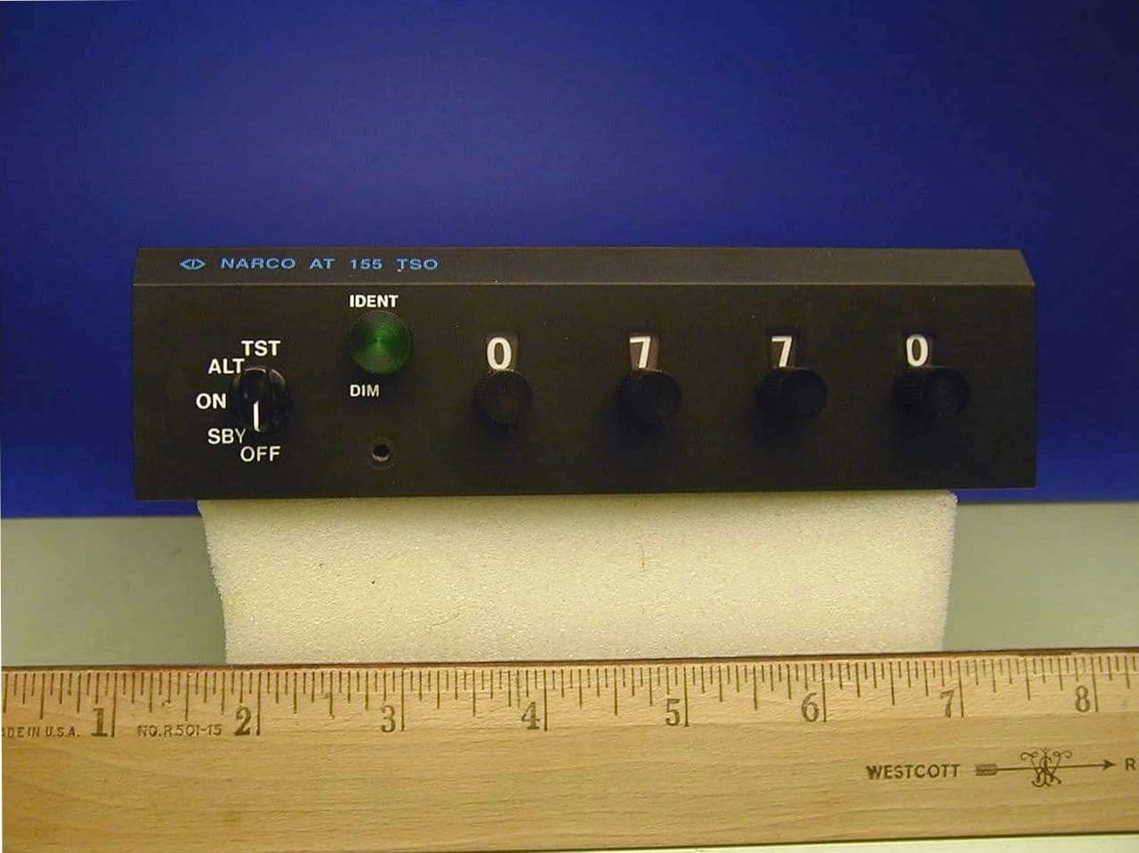
Click to zoom
Application Details
- Equipment Class
- TNB - Licensed Non-Broadcast Station Transmitter
- Date of Grant
- Sep 02, 2002
- Application Purpose
- Original Equipment
- Date of Application
- Jul 08, 2002
- Equipment Note
- Aviation Transponder
- Frequency Range
- 1090.00000000 - 1090.00000000
- Company
- Narco Avionics Inc
- Country
- United States
Documents & Files
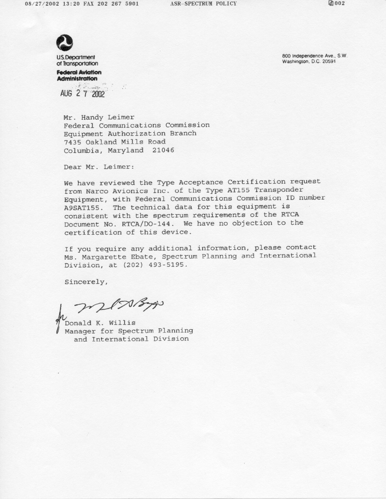
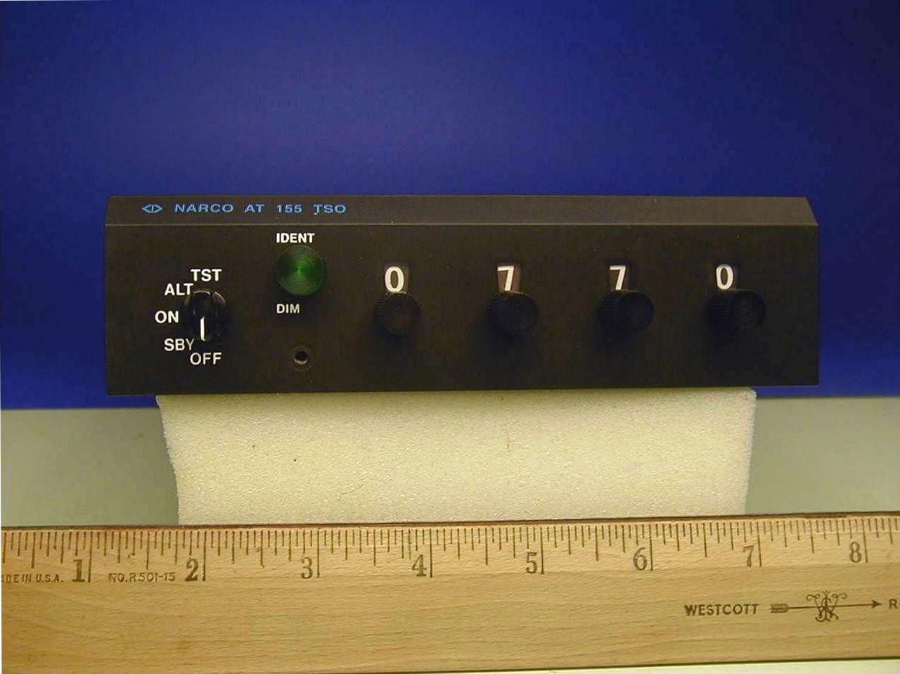
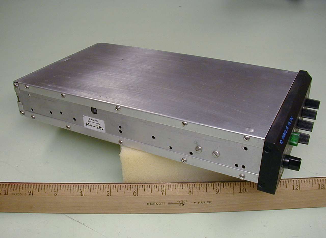
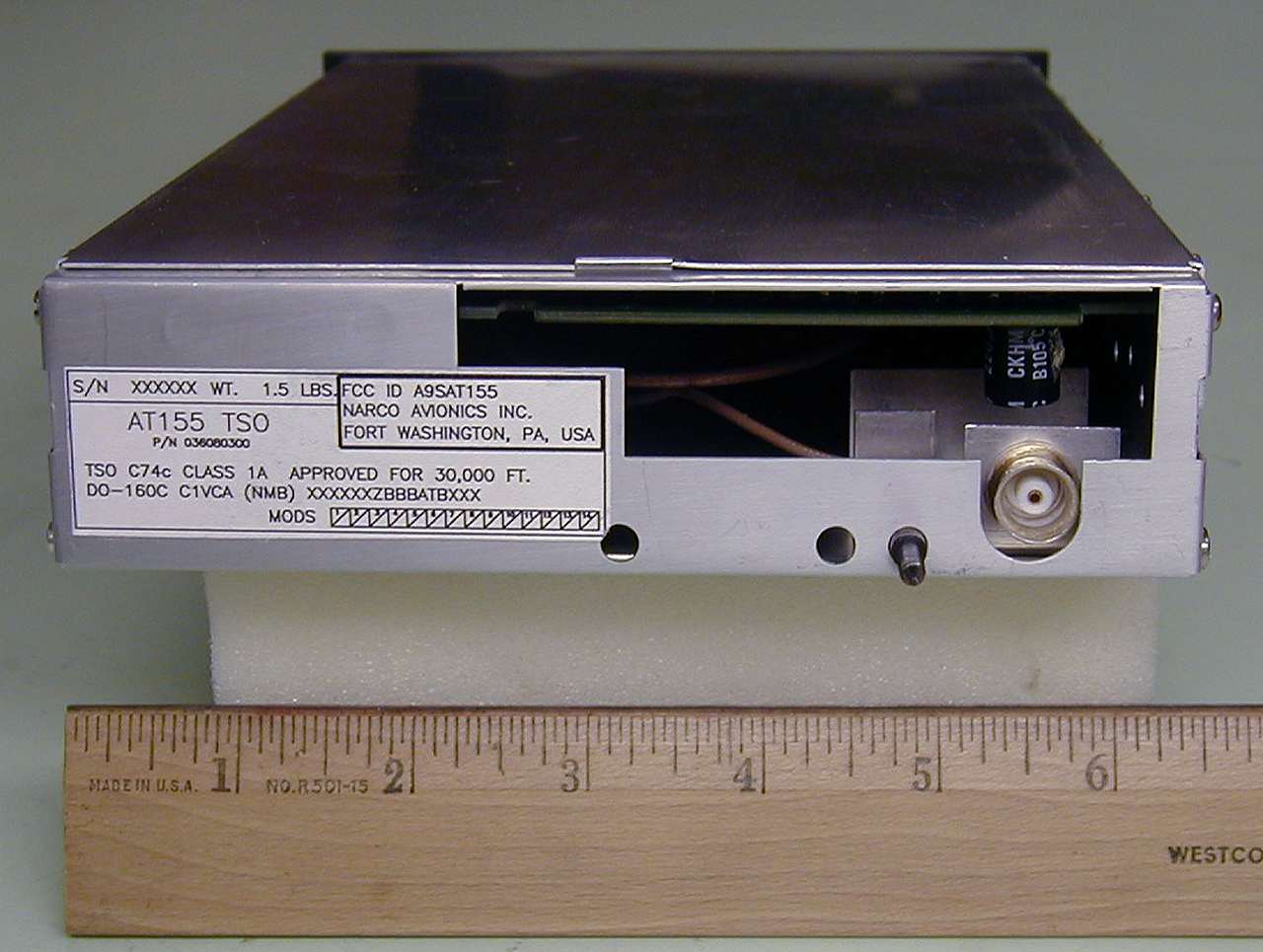
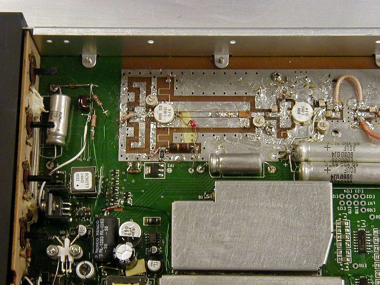
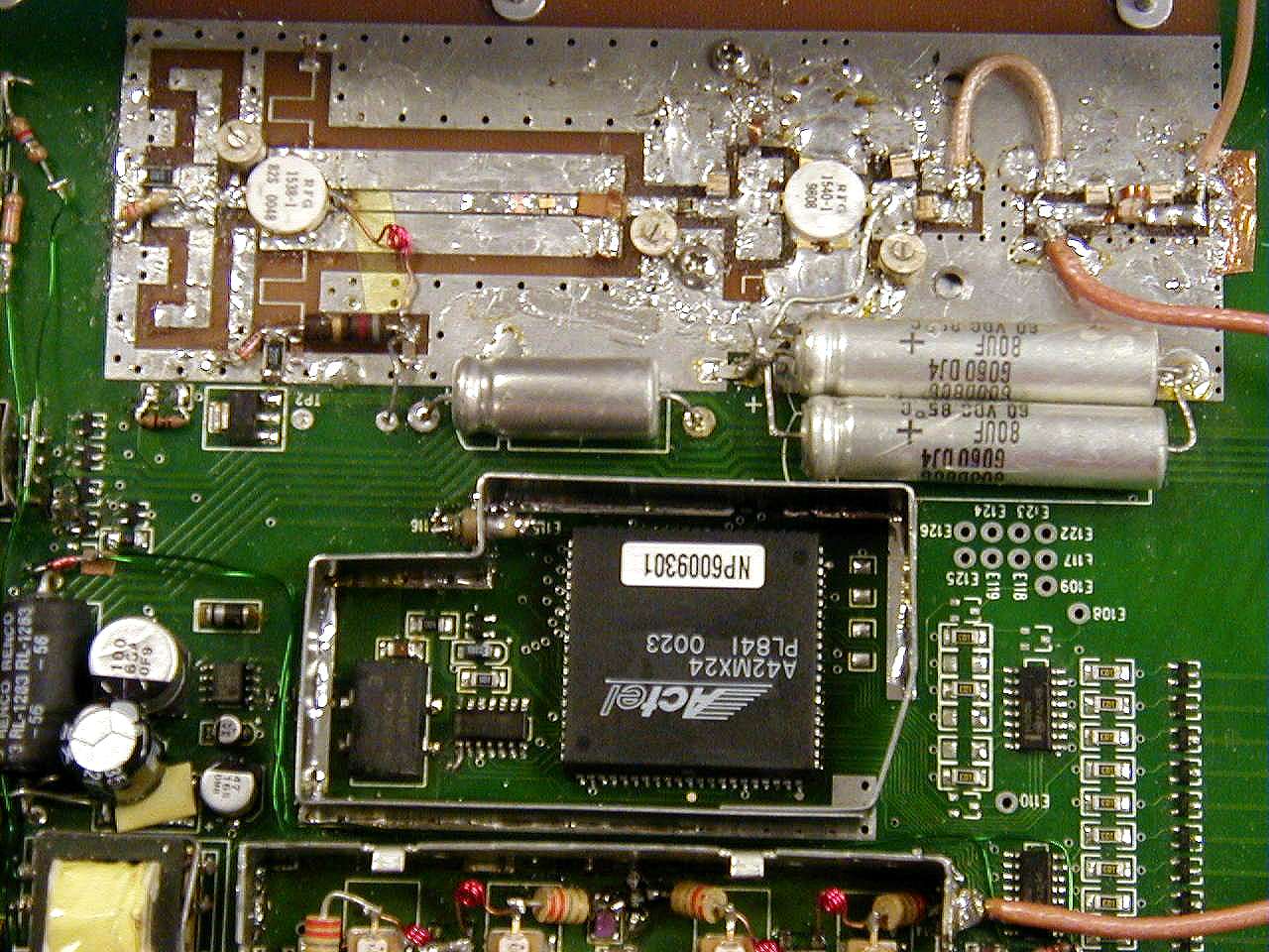
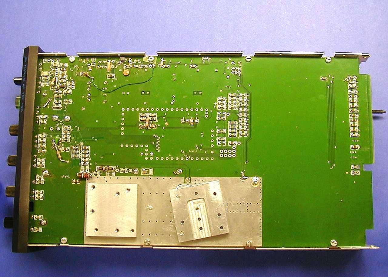
Document Text
Text extracted from the exhibit documents filed with the FCC. Open a document above to read the original.
Users Manual
PRINTED IN U.S.A. REV 1.0MAY, 2002 Narco Avionics AT155 TSO Transponder Installation Manual 03608-0620 Narco Avionics Inc. 270 Commerce Drive Ft. Washington, Pa. 19034 U.S.A. REV 1.0 NOTICE While every effort has been made by Narco Avionics Inc. to ensure accuracy in the preparation of this Installation Manual, Narco assumes no responsibility for errors or omissions Narco Avionics can be reached by calling : Phone : 215-643-2900 FAX : 215-643-0197 Or on the Internet at www.narcoavionics.com May, 2002 REV 1.0i Narco Avionics AT155 TSO TABLE OF CONTENTS SECTION NUMBERTITLE PAGE NUMBER 1.1GENERAL 1-1 1.1.1 Manual Organization 1-1 1.2PRODUCT DESCRIPTION 1-1 1.3 PRODUCT SPECIFICATIONS 1-2 1.4 TSO EXPLANATION 1-3 1.4.1 AT155 Antenna 1-3 1.5UNITS AND ACCESSORIES SUPPLIED 1-3 1.6 OPTIONAL ACCESSORIES1-4 1.7 MISCELLANEOUS ITEMS REQUIRED BUT NOT SUPPLIED.1-4 1.8 OPERATOR LICENSE REQUIIREMENTS1-4 1.9 OPERATION 1-5 1.9.1 Function Selector Switch1-5 1.9.2 IDENT/DIM1-6 1.9.3 Code Selector1-6 2.1 INTRODUCTION 2-1 2.2 PRELIMINARY INSPECTION 2-1 2.2.1 Unpacking 2-1 2.2.2 Electrical Bench Test. 2-2 2.2.2.1 Test Equipment Required. 2-2 2.2.2.2 Test Procedure 2-2 2.3 MECHANICAL INSTALLATION. 2-5 2.3.1 Mounting Tray 2-5 2.3.2 Insertion And Removal Of The AT155 2-5 2.4 ANTENNA INSTALLATION 2-7 2.4.1 Antenna Location And Mounting. 2-7 2.4.2 Antenna Extension Cable. 2-8 2.5 ELECTRICAL INSTALLATION 2-9 2.5.1 Power And Interconnect Cable 2-9 2.5.2 Cable Fabrication 2-11 2.5.3 Pilot Lamps 2-12 2.5.4 External Suppression 2-12 2.5.5 Remote IDENT 2-13 2.5.6 Altitude Digitizer 2-13 2.6 POST INSTALLATION TESTS 2-13 2.6.1 Preflight Tests 2-13 2.6.2 Flight Test 2-14 2.7AIRCRAFT LICENSE REQUIREMENTS.2-14 APPENDIX A – CERTIFICATION DOCUMENTS A.1ENVIRONMENTAL QUALIFICATION FORMA-1 A.2CONTINUED AIRWORTHINESSA-2 R.1MANUAL REVISION HISTORYR-1 ii REV 1.0May, 2002 LIST OF ILLUSTRATIONS FIGURE NUMBERTITLE PAGE NUMBER 1-1AT155 TSO FRONT PANEL1-7 2-1BENCH TEST SET-UP2-2 2-2INSTALLATION DIAGRAM2-6 2-3AT155 ANTENNA MOUNTING2-7 2-4POWER AND INTERCONNECT CABLE2-9 2-5ORIENTATION DIAGRAM2-10 2-6CRIMPING TOOL2-11 2-7PILOT LAMP CONVERSION (SWITCH)2-12 LIST OF TABLES TABLE NUMBERTITLE PAGE NUMBER 1.1UNITS AVAILABLE1-3 1.2INSTALLATION KIT (3604-0500)1-4 2.1ALTITUDE DIGITIZER INPUTS2-4 INTRODUCTION SECTION 1 May, 2002 REV 1.01-1 1.1GENERAL In support of the Narco Avionics AT155 TSO Transponder, this manual provides detailed installation and operation procedures. "This manual is intended for use only by persons qualified to service equipment in this manual pursuant to current regulatory requirements." 1.1.1 Manual Organization Organized into two major sections the manual inc ludes the following: Section 1, Introduction - general information required in planning the installation Section 2, Installation - detailed procedures for performing the mechanical and electrical installation 1.2 PRODUCT DESCRIPTION The AT155 TSO consists of a receiver tuned to the frequency of a ground interrogation station (1030 MHz), logic circuitry to check the validity of the received interrogation and encode a reply containing pertinent identification information, and a transmitter which sends the coded reply to the ground station. When an optional altitude digitizer, Narco Model AR-850, is incorporated, coded altitude information will be transmitted to the ground station. The AT155 has been designed for 14V or 28V operation. If the AT155 is replacing an existing AT50A or AT150 that uses an MP10 or a passive voltage converter these do not have to be removed. Narco Avionics AT155 1-2 REV 1.0May, 2002 1.3 PRODUCT SPECIFICATIONS Mechanical Physical Dimensions and MountingRefer to appropriate diagram in Section 2 Weight1.5lbs. (0.68kg) Electrical Power Requirements 13.75 VDC 27.5VDC Standby 210mA125mA Transmit 1.2 A530mA Pilot Lamps 220mA90mA Receiver Frequency1030 MHz Frequency Stability Crystal Controlled Sensitivity Minimum trigger level (MTL) -69 to -74 dBm Side-Lobe Suppression (SLS)99% or greater for signals from 3 dB to 50 dB above MTL Dynamic Range Logarithmic pulse response 50 dB or greater above MTL Bandwidth-60dB at ± 25 MHz Decoding Capability Mode A Pulse pair spaced at 8 ±0.5μs Mode C Pulse pair spaced at 21 ±0.5μs Side-Lobe Suppression35 μs suppression upon receipt of two pulses spaced 2 ±0.5μs apart. Encoding Capability Mode A4096 reply codes selectable by front panel switches. Mode C Altitude reporting to 30,700 feet SPIP (Special Position An SPIP may be added to mode A for 20 ±5 seconds Identification Pulse) Transmitter Frequency1090 MHz Pulse Power 250 watts nominal, 190 watts minimum External Interference Suppression (positive) Pulse Amplitude5 to 50 volts Load on Suppressor3300 ohms External Interference Suppression (negative) Voltage0.8V (maximum) Current5 mA INTRODUCTION SECTION 1 May, 2002 REV 1.01-3 1.4TSO EXPLANATION The TSO'd AT155 is designed to be instrument panel mounted within the cabin environment of fixed and rotary wing aircraft using piston or turbine single or multi-engines. It will operate and has been tested up to 30,000 feet for installations in non-pressurized as well as pressurized aircraft. This equipment requires direct current power but is designed to be installed in aircraft that have additional on board alternating current sources. Environmental testing was done to RTCA Document DO-160C. The Environmental categories are listed in Appendix A of this document. 1.4.1 AT155 Antenna The AT155 Antenna meets the requirements of TSO-C74b Class 1, Environmental Category /JA/JAAAXXXXXX. 1.5 UNITS AND ACCESSORIES SUPPLIED The following two tables may be used to: 1) check the contents of your order and, 2) to order additional Units or components. TABLE 1.1 UNITS AVAILABLE Unit Part Number Unit and DescriptionSubassembly Part Number 03608-0300 AT155 TRANSPONDER ASSY, Complete with: AT155 Transponder, Tray Assy Antenna Assy Installation Kit 01545-0101 56282-0102 71233-0101 03604-0500 Narco Avionics AT155 1-4 REV 1.0May, 2002 TABLE 1.2. INS…
Text truncated - open the document above for the full version.
Cover Letter(s)
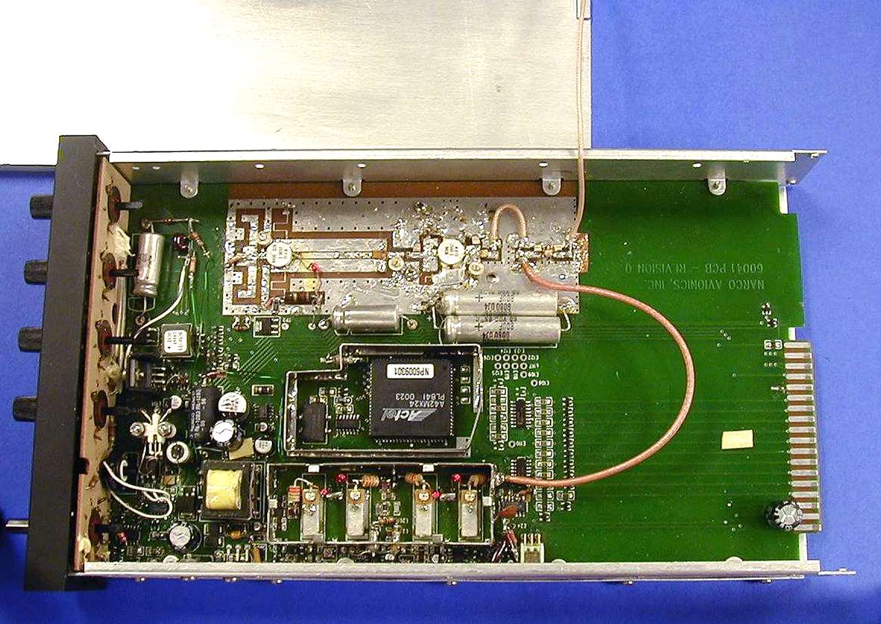
NARCO AVIONICS INC. 270 COMMERCE DR., FORT WASHINGTON PA 19034 (215)-643-2900 FAX (215)-643-2498 JULY 3, 2002 Federal Communications Commission 7435 Oakland Mills Road Columbia, MD 21046 Gentlemen: This letter is to comply with Section 0.457(d)(2)(i) pertaining to confidential material . Narco Avionics Inc. would like the following documents in this submission for FCC ID: A9SAT155 to be kept confidential: 1. Page 1 of 1 of document D-02750, schematic AT155 Main board. 2. Page 1 of 7 of document ER1400, FCC technical information. 3. Picture AT155intback.jpg, internal picture. 4. Picture AT155inttopnoshld.jpg, internal picture. 5. Picture AT155inttopshl.jpg, internal picture. 6. Picture AT155intxmt.jpg, internal picture. The above material contains trade secrets or technical data, which would customarily be guarded from our competition. We do not want this information to be available to the general public. Sincerely, Martin Lockner Manager, Engineering [email protected]
Cover Letter(s)
NARCO AVIONICS INC. 270 COMMERCE DR., Suite 200, FORT WASHINGTON PA 19034 (215)-643-2900 FAX (215)-643-2498 July 3, 2002 FAA, Spectrum Engineering Division 800 Independence Ave. SW. Washington, DC 20591 Dear Sir, The intent of this letter is to advise your agency that Narco Avionics Inc. Is applying for FCC certification of the Type AT155 Transponder Equipment. Listed below is the information required by your agency: Manufacturer:Narco Avionics Inc. 270 Commerce Drive Fort Washington, Pa 19034 Type Number:AT155 FCC ID:A9SAT155 Antenna Characteristics:Rod type antenna which is ¼ wave length at 1090Mhz. Rated Power out:125 watts minimum at antenna end of transmission line. Transmitter Frequency:1090Mhz Type and Character of Emission:Pulse type modulation. FCC designation – M1D Transmitter Occupied Bandwidth:14Mhz ( 99% of radiated power) Receiver Characteristics:Receiver center frequency 1030Mhz. Bandwidth at 60db points ± 25Mhz Purpose:The AT155 transponder is used for receiving ATC interrogations and replying to same, both for aircraft identification and altitude data. The AT155 will be TSO’d. The application for TSO will be filed with the NYACO. Very Truly Yours, Martin Lockner Manager, Engineering [email protected]
Cover Letter(s)
NARCO AVIONICS INC. 270 COMMERCE DR., FORT WASHINGTON PA 19034 (215)-643-2900 FAX (215)-643-2498 September 3, 2002 Federal Communications Commission 7435 Oakland Mills Road Columbia, MD 21046 Gentlemen: This letter is to comply with Section 0.457(d)(2)(i) pertaining to confidential material . Narco Avionics Inc. would like the following documents in this submission for FCC ID: A9SAT155 to be kept confidential: 1. Page 1 of 1 of document D-02750, schematic AT155 Main board. 2. Page 1 of 7 of document ER1400, FCC technical information. The above material contains trade secrets or technical data, which would customarily be guarded from our competition. We do not want this information to be available to the general public. Sincerely, Martin Lockner Manager, Engineering [email protected]
Operational Description
PRINTED IN U.S.A.MAY, 2002 N ARCO A VIONICS AT155 TSO Transponder Operation Manual 03608-0621 N ARCO A VIONICS INC. 270 Commerce Drive Ft. Washington, PA. 19034 U.S.A. NOTICE While every effort has been made by Narco Avionics Inc. to ensure accuracy in the preparation of this Operation Manual, Narco assumes no responsibility for errors or omissions NARCO AVIONICS CAN BE REACHED BY CALLING : 215-643-2900 FAX : 215-643-0197 MAY, 20021 PRODUCT DESCRIPTION The AT155 TSO consists of a receiver tuned to the frequency of a ground interrogation station (1030 MHz), logic circuitry to check the validity of the received interrogation and encode a reply containing pertinent identification information, and a transmitter which sends the coded reply to the ground station. When an optional altitude digitizer, Narco Model AR-850, is incorporated, coded altitude information will be transmitted to the ground station. The AT155 has been designed for 14V or 28V operation. If the AT155 is replacing an existing AT50A or AT150 that uses an MP10 or a passive voltage converter these do not have to be removed. OPERATION FIGURE 1-1 AT 155 FRONT PANEL Function Selector Switch The function selector is a five position rotary switch. The five positions are: OFF- Turns OFF all power to the transponder. SBY- Turns the transponder power supply ON. When in SBY, the transponder will not reply to any interrogation. SBY is used at the request of the air traffic controller to selectivity clear his scope of traffic. ON-Places the transponder in Mode A, the aircraft identification mode. In addition to the aircraft's identification code, the transponder will a lso reply to alt itude interrogations (Mode C) with discreet signals that do not contain altitude information. ALT- The ALT position activates all the necessary circuitry (transponder to optional altitude digitizer and return) to respond to ATC (Air Traffic Control) altitude interrogations and aircraft identification interrogations with standard pressure altitude (29.92 inches Hg). The ALT position may be used in aircraft that are not equipped with the optional altitude digitizer, however, the only response will be discreet signals that do not contain altitude information. 2MAY, 2002 TST- Turning the switch to the TST position injects a test signal into the transponder. This test signal tests all transponder circuitry involved in a Mode A reply and causes the IDENT/DIM button to come on at full brilliance. This full brilliance indicated that transponder has the capability of receiving and responding to interrogations. The TST function may be activated at anytime, as it does not interfere with normal operation. The TST position is spring loaded and must be held in position during the test process. Upon release, it will automatically return to the ALT position. Ident/Dim When the aircraft comes within range of a ground station, the IDENT/DIM button will blink ON and OFF. Momentarily depressing the IDENT/DIM button will activate the SPIP (Special Position Identification Pulse) signal for approximately 20 seconds. This signal will "paint" an instantly identifiable image on the controllers scope. This signal must only be used upon request of a "Squawk IDENT" from the controller. Use at any other time could interfere with another aircraft sending a SPIP. During "'IDENT" periods, the IDENT/DIM button will glow constantly. Rotating the IDENT/DIM button will control the intensity at which the button glows. Code Selector The CODE SELECTOR consists of four eight position switches that provide 4096 active identification codes. The identification code is selected by the controller.
Test Report
ER1401 NARCO AVIONICS AT155 TRANSPONDER FCC FREQUENCY STABILITY REPORT PURPOSE OF THIS REPORT This report contains the technical information required by the FCC in 47 CFR Part 2.1055. TEMPERATURE VARIATION TEMPERATURE IN °CFREQUENCY IN MHZ +501087.8 +301088.5 +101089.4 -101091.9 -201092.4 VOLTAGE VARIATION The AT155 contains a voltage regulator and the frequency of the transmitter is not affected by variations of the primary supply voltage. The normal operating voltages for the AT155 are 13.75V and 27.5V. The AT155 was tested over the range of 10V to 35V.
Test Report
FCC TEST REPORT Prepared for NARCO AVIONICS on the AT-155 AIR TRAFFIC CONTROL TRANSPONDER Report No. 02_0790 June 28, 2002 20 Clipper Road West Conshohocken, PA 19428-2721 Phone: 610-825-1960 Fax: 610-825-1684 [email protected] rb.iitri.org Report No.02_0790 Revision Page No.1 of 29 IIT Research Institute R&B Laboratory 20 Clipper Road West Conshohocken, PA 19428-2721 610-825-1960 FCC TEST REPORT Prepared for Narco Avionics on the AT-155 Air Traffic Control Transponder Report No. 02_0790 June 28, 2002 Customer: Narco Avionics Fort Washington, PA P.O. Number: 22989-00 Job Number: 0790 Requirement: FCC Part 87 This document shall not be reproduced, except in full, without the written approval of IIT Research Institute, R&B Laboratory. This document cannot be used to claim a product endorsement by NVLAP or any agency of the U.S. Government. Report No.02_0790 Revision Page No.2 of 29 TABLE OF CONTENTS SECTIONTITLEPAGE ADMINISTRATIVE DATA........................................................4 EXECUTIVE SUMMARY.........................................................5 1 GENERAL INFORMATION.................................................6 1.1DESCRIPTION OF EQUIPMENT UNDER TEST (EUT)....................6 1.2MODE OF OPERATION............................................6 2 APPLICABLE DOCUMENTS ............................................... 7 3 TEST FACILITIES.......................................................8 3.1SCOPE.........................................................8 3.2TEST SITE.......................................................8 3.3OPEN-AREA RADIATED EMISSIONS TEST SITE........................8 3.3TEST EQUIPMENT................................................9 3.3.1Calibration.................................................9 3.3.2Measurement-Receiver Characteristics..........................9 4 RF POWER OUTPUT ................................................... 10 4.1SCOPE........................................................10 4.2TEST PROCEDURE..............................................10 4.3TEST RESULTS.................................................10 4.4LIST OF TEST EQUIPMENT........................................10 5 MODULATION CHARACTERISTICS ........................................ 12 5.1SCOPE........................................................12 5.2TEST PROCEDURE..............................................12 5.3TEST RESULTS.................................................12 5.4LIST OF TEST EQUIPMENT........................................12 6 OCCUPIED BANDWIDTH................................................14 6.1SCOPE........................................................14 6.2TEST PROCEDURE..............................................14 6.3TEST RESULTS.................................................14 6.4LIST OF TEST EQUIPMENT........................................14 7 SPURIOUS EMISSIONS ................................................. 16 7.1SCOPE........................................................16 7.2TEST PROCEDURE..............................................16 7.3TEST RESULTS.................................................16 7.4LIST OF TEST EQUIPMENT........................................16 Report No.02_0790 Revision Page No.3 of 29 8 FIELD STRENGTH OF SPURIOUS RADIATION .............................. 21 8.1SCOPE........................................................21 8.2TEST PROCEDURE..............................................21 8.3TEST RESULTS.................................................21 8.4LIST OF TEST EQUIPMENT........................................21 APPENDIX A DATA FOR MODULATION CHARACTERISTICS APPENDIX B DATA FOR OCCUPIED BANDWIDTH APPENDIX C DATA FOR SPURIOUS EMISSIONS Report No.02_0790 Revision Page No.4 of 29 ADMINISTRATIVE DATA Purpose of Test:To demonstrate completion of the Narco Avionics, Air Traffic Transponder, with FCC Part 87. Equipment Tested:Model No: AT-155 S/N: E-01 Manufacturer:Narco Avionics Test Specification:FCC Rules and Regulations, Part 2 and 87 Test Personnel:Scott Williamson EMC Engineer Customer Representative:M. Lockner Narco Avionics Date of Test:June 25, 2002 Test Location:IIT Research Institute R&B Laboratory 20 Clipper Road West Conshohocken, PA 19428 Disposition of Item Tested:Returned via Customer Representative Report No.02_0790 Revision Page No.5 of 29 EXECUTIVE SUMMARY The Narco Avionics, Air Traffic Control Transponder, Model No. AT-155, Serial No. E-01 was tested in accordance with the procedures in FCC Part 2 for compliance with the requirements of the FCC Rules and Regulations, Part 87. The Equipment Under Test (EUT) completed all requirements as summarized below. The detailed test results can be found in the appropriate sections of this report. Test MethodSection RF Power Output 2.1046 4 Modulation Characteristics 2.1047 5 Appendix A Occupied Bandwidth 2.1049 6 Appendix B Spurious Emissions 2.1051 7 Appendix C Field Strength of Spurious Radiation 2.1053 8 Report No.02_0790 Revision Page No.6 of 29 SECTION 1 GENERAL INFORMATION 1.1DESCRIPTION OF EQUIPMENT UNDER TEST (EUT) The Air Traffic Control Transponder has a receiver tuned to 1030 MHz, with a coded ground interrogator which requests replies of code switch settings or altitude. Response is .45 μs pulses at 1090 MHz. A maximum of 1200 replies per second and a maximum of 15 pulses per reply is possible. 1.2MODE OF OPERATION ON OFF StandBy Altitude Test ( All Tests were performed in the Altitude Mode) Report No.02_0790 Revision Page No.7 of 29 SECTION 2 APPLICABLE DOCUMENTS ANSI C63.4-1992 17 July 1992 “American National Standard for Methods of Measurement of Radio-Noise Emissions from Low-Voltage Electrical and Electronic Equipment in the Range of 9 kHz to 40 GHz” ISO 10012-1:1992(3) 1 April 1996 “Quality Assurance Requirements for Measuring Equipment Part 1: Metrological Confirmation System for Measuring Equipment” ANSI/NCSL Z540-1:1994 27 July 1994 “American National Standard for Calibration General Requirements - Calib…
Text truncated - open the document above for the full version.
Test Report
1 ER1402 (ADDENDUM July 2002) NARCO AVIONICS AT155 TRANSPONDER FCC TESTING 2 PREFACE Upon examination of the FCC test report submitted to Narco Avionics by IITRI R & B Laboratories it was noted that the XPDR/DME generator listed on page 10 of the report was out of calibration. This piece of test equipment was originally provided to R & B to provide a stimulus to the AT155 so it would transmit (calibration not required). In preparation for the test R & B asked Narco if we had any suggested method for measuring the power output of the AT155. We suggested they use the generator that they already had (we were not aware of the calibration issue since the generator was not originally provided as a measurement device). When we noticed the expired calibration on the generator we tested the FCC AT155 (S/N E-01) on a calibrated generator and found that the two generators agreed on the power level. TEST EQUIPMENT USED ITEMCHARACTERISTICSMANUFACTURERMODEL NO.SERIAL N0.CAL DUE XPDR/DME Simulator IFRATC-1200Y4109425 JAN 2003 TEST RESUL TS FCC PART 87RF POWER OUTPUT SETTINGRESULTS “0000”200W “7777”200W Martin Lockner Manager, Engineering
Test Report
NARCO AVIONICS INC. 270 COMMERCE DR., FORT WASHINGTON PA 19034 (215)-643-2900 FAX (215)-643-2498 Date: August 19, 2002 Federal Communications Commision Laboratory Division 7435 Oakland Mills Road Columbia, MD 21046 Attention: Andy Leimer FCC ID: A9SAT155 In reference to your letter dated August 14 th 2002 regarding denial of approval for the AT155, we believe the frequency tolerance you have referenced applies to DME airborne transmitters. The frequency tolerance for the ATC transponder system is defined in FAA document TSO C74c paragraph 2.10 as 1090MHz ± 3MHz. Note that the 3MHz authorized by the FAA is a significantly tighter tolerance (TSO C74c pages 1 to 6 are enclosed) than that authorized by the FCC part 87.133.d which would be equal to the authorized frequency band less 1.5/T relative to the upper and lower authorized band edges. In this instance it would be equal to the authorized bandwidth less 1.5/.45μs or 3.3MHz from the upper and lower frequency. TSO C74c 2.13d defines the maximum occupied bandwidth as that which would be created by a trapezoidal waveform having the minimum specified rise and fall times. This calculates a maximum occupied bandwidth of about 20MHz. This equates to an FCC frequency tolerance of (20- 6.66MHz)/2 which is ±6.667MHz. Since the FAA is the stricter of the two it is regarded as the applicable limit. 14MHz was chosen as the nominal bandwidth for the emission designator as it represents the worst case spectrum for the pulse rise and fall times for the design parameters implemented. TSO C74c 2.11.a specifies a peak pulse power of 21db above 1 watt at the antenna end of the transmission line. This translates to 125.9 watts at the antenna. Eight feet of RG-223 was used between the AT155 and the power detector. This represents 1.32db loss in the test setup. (RG223 loss=16.5db/100ft@ 1Ghz). With an indicated 200W output (Re: the test report), this represents 270W at the rear connector of the transponder. With the maximum allowable Narco specified cable loss of 2db this results in 170 watts at the antenna, comfortably above the minimum of 125.9 watts specified To confirm the peak power data used in the submission, measurements were made using a spectrum analyzer . A calibrated pulse generator (ATC1400 Y4 , LT176-1, Cal date Jan. 25, 2002) was driven directly into the input terminals (0 dbm) of an IFR AN1820 spectrum analyzer. With a rate of 1000 replies per second, 2 pulses per reply and a pulse width of 0.45 μs the analyzer displayed a main lobe response of –43dbm. This represents the “measurement losses” due to the bandwidths of the analyzer. The AT155 transmitter with pulses identical to the signal generator was then substituted through a variable attenuator. The attenuator was then adjusted for the identical main lobe on the analyzer. The attenuation required was 54 db. 54db above 0 dbm is a power of 252 watts. Since the granularity of the attenuator was 1db (+25%, -21% in power) this is considered good confirmation of the actual peak power. Enclosed is a photograph of the spectrum analyzer screen showing monotonic decreasing sideband energy beyond that shown in the IITRI R&B Laboratories report on occupied bandwidth. If you have any questions please contact me. Sincerely, Martin Lockner Manager, Engineering Narco Avionics Inc. [email protected] 215-643-2900 x616
Contact Information
Applicant
Martin Lockner
Technical Contact
Narco Avionics Inc.Martin J Lockner
[email protected]215-643-2900
270 Commerce Dr · Fort Washington, Pennsylvania · United States
Technical Specifications
| # | Rule Parts | Frequency Range | Power Output | Emission | Tolerance |
|---|---|---|---|---|---|
| 1 | 87 | 1.09 GHz - 1.09 GHz | 200 W | 14M0M1D | 0.2750000000 % |
Other Applications from Narco Avionics Inc
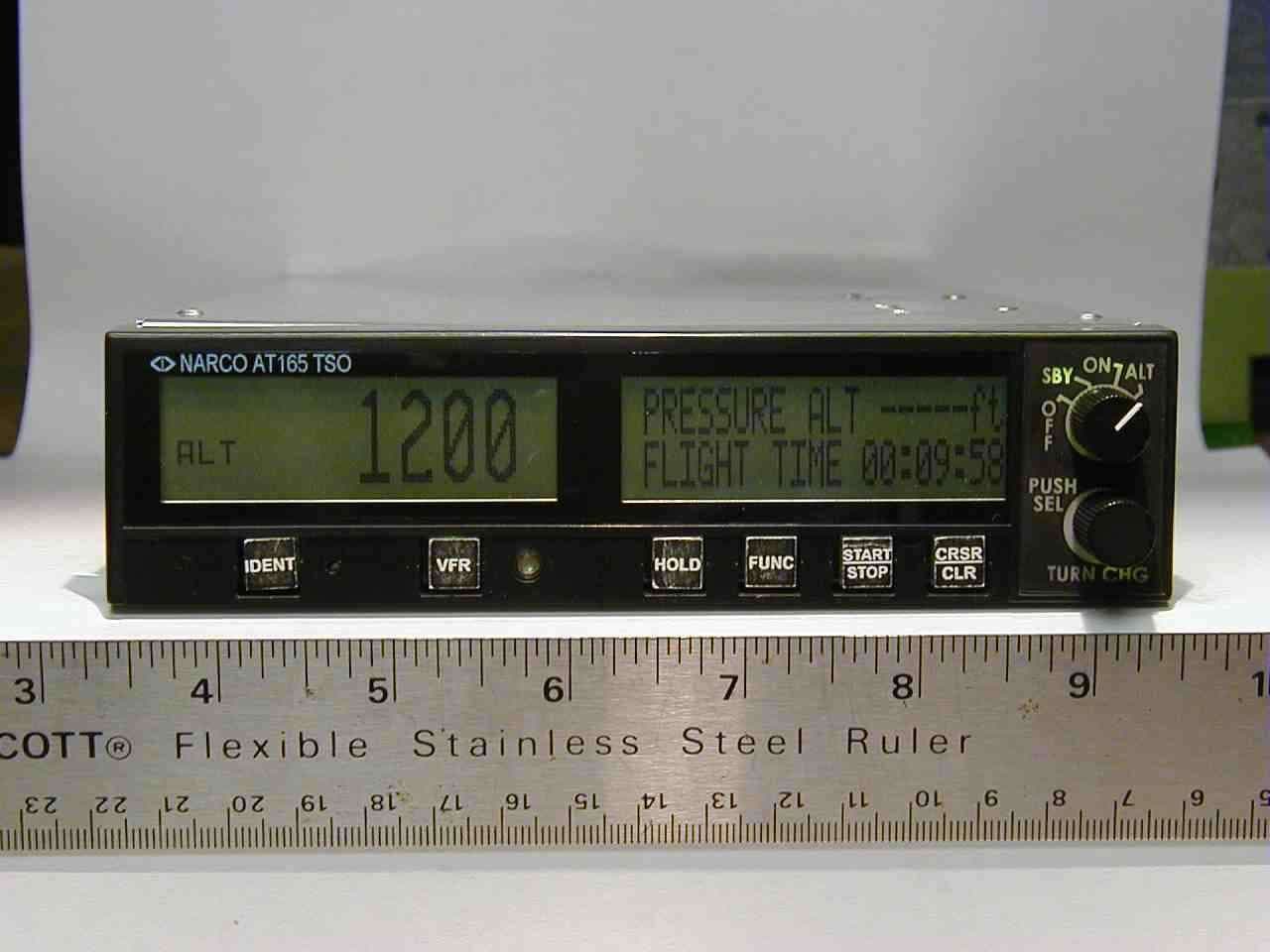
A9SAT165
Jul 13, 2004Aviation Transponder
Equipment Class
TNB - Licensed Non-Broadcast Station TransmitterA9SNAV122D
Mar 17, 1998CXX - Communications Rcvr for use w/ licensed Tx and CBs
Equipment Class
CXX - Communications Rcvr for use w/ licensed Tx and CBsA9SMK12D76014V
Aug 19, 1991TNB - Licensed Non-Broadcast Station Transmitter
Equipment Class
TNB - Licensed Non-Broadcast Station TransmitterA9SMK12D76028V
Aug 19, 1991TNB - Licensed Non-Broadcast Station Transmitter
Equipment Class
TNB - Licensed Non-Broadcast Station TransmitterA9SCOM120-20GTSO
Jul 25, 1991TNB - Licensed Non-Broadcast Station Transmitter
Equipment Class
TNB - Licensed Non-Broadcast Station Transmitter