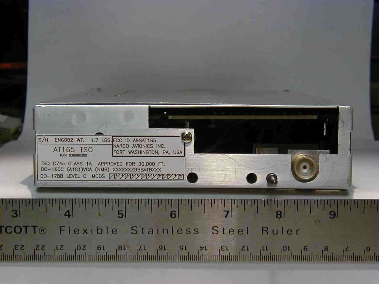
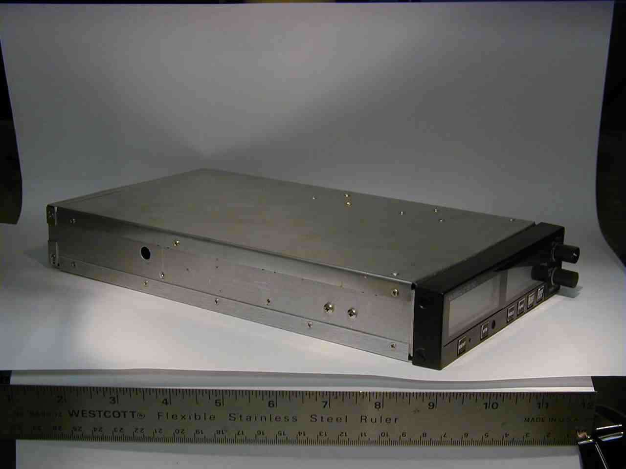
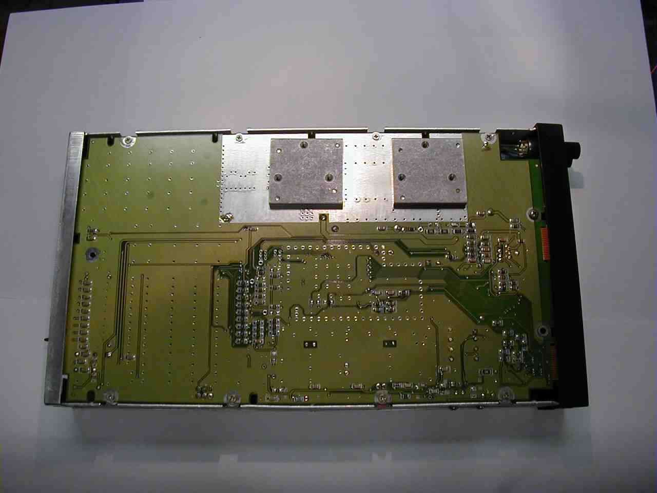
A9SAT165Aviation Transponder
Narco Avionics Inc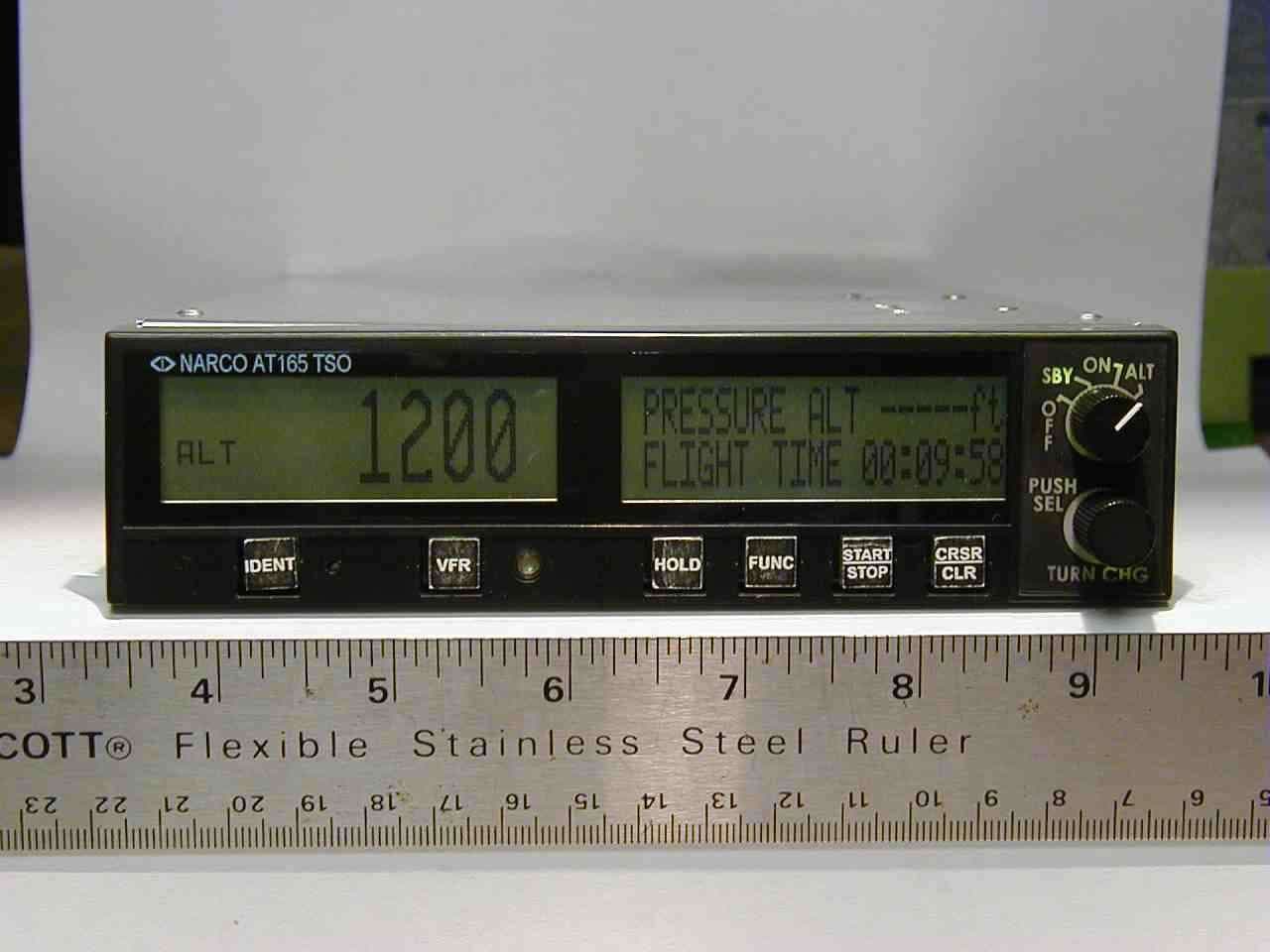
Click to zoom
Application Details
- Equipment Class
- TNB - Licensed Non-Broadcast Station Transmitter
- Date of Grant
- Jul 13, 2004
- Application Purpose
- Original Equipment
- Date of Application
- May 16, 2004
- Equipment Note
- Aviation Transponder
- Frequency Range
- 1090.00000000 - 1090.00000000
- Company
- Narco Avionics Inc
- Country
- United States
Documents & Files

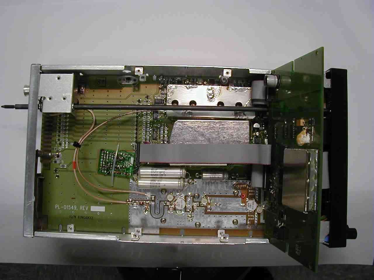

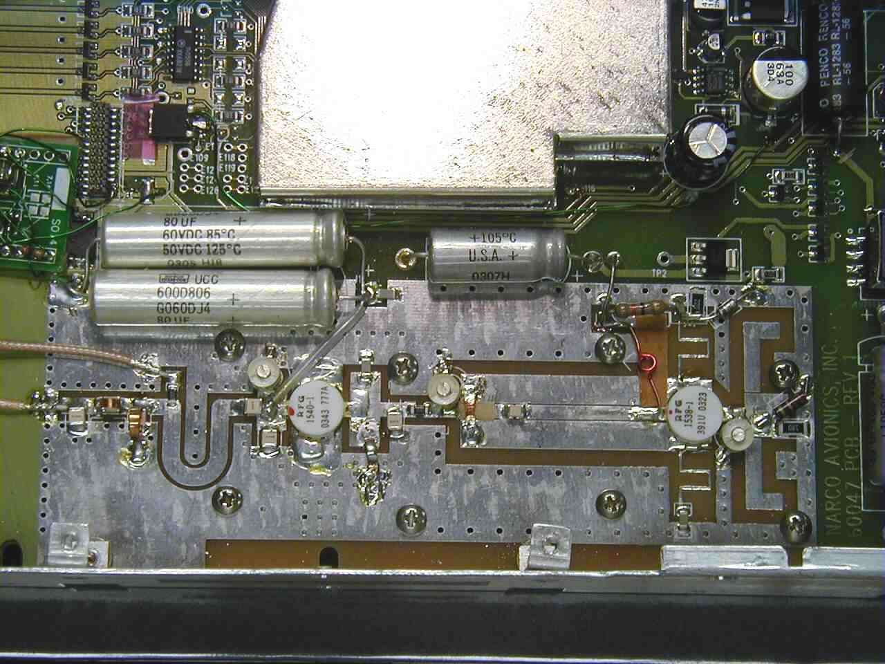
Document Text
Text extracted from the exhibit documents filed with the FCC. Open a document above to read the original.
Users Manual
PRINTED IN U.S.A. REV 1.0 March, 2004 Narco Avionics AT165 TSO Transponder Installation Manual 03609-0620 Narco Avionics Inc. 270 Commerce Drive, Suite 200 Ft. Washington, Pa. 19034 U.S.A. REV 1.0 NOTICE While every effort has been made by Narco Avionics Inc. to ensure accuracy in the preparation of this Installation Manual, Narco assumes no responsibility for errors or omissions Narco Avionics can be reached by calling : Phone : 215-643-2900 FAX : 215-643-0197 Or on the Internet at www.narcoavionics.com The AT165 is dedicated to John Bail (1929-2003). John , as Vice President of Engineering and later as a consultant, was instrumental in the development of many of Narco’s best selling products including the AT165. March, 2004 REV 1.0 i Narco Avionics AT165 TSO TABLE OF CONTENTS SECTION NUMBER TITLE PAGE NUMBER 1.1 GENERAL 1-1 1.1.1 Manual Organization 1-1 1.2 PRODUCT DESCRIPTION 1-1 1.3 PRODUCT SPECIFICATIONS 1-2 1.4 TSO EXPLANATION 1-3 1.4.1 AT165 Antenna 1-3 1.5 UNITS AND ACCESSORIES SUPPLIED 1-3 1.6 OPTIONAL ACCESSORIES 1-4 1.7 MISCELLANEOUS ITEMS REQUIRED BUT NOT SUPPLIED. 1-4 1.8 OPERATOR LICENSE REQUIIREMENTS 1-4 1.9 OPERATION 1-5 1.9.1 Function Selector Switch 1-5 1.9.2 CODE SELECTOR/DATA ENTRY 1-6 1.9.3 IDENT 1-6 1.9.4 VFR 1-6 1.9.5 HOLD 1-6 1.9.6 FUNC 1-7 1.9.7 START/STOP 1-7 1.9.8 CRSR/CLR 1-7 2.1 INTRODUCTION 2-1 2.2 PRELIMINARY INSPECTION 2-1 2.2.1 Unpacking 2-1 2.2.2 Electrical Bench Test. 2-2 2.2.2.1 Test Equipment Required. 2-2 2.2.2.2 Test Procedure 2-2 2.3 MECHANICAL INSTALLATION. 2-5 2.3.1 Mounting Tray 2-5 2.3.2 Insertion And Removal Of The AT165 2-5 2.4 ANTENNA INSTALLATION 2-7 2.4.1 Antenna Location And Mounting. 2-7 2.4.2 Antenna Extension Cable. 2-8 2.5 ELECTRICAL INSTALLATION 2-9 2.5.1 Power And Interconnect Cable 2-9 2.5.2 Cable Fabrication 2-11 2.5.3 Pilot Lamps 2-12 2.5.4 External Suppression 2-12 2.5.5 Remote IDENT 2-13 2.5.6 Altitude Digitizer 2-13 2.6 POST INSTALLATION TESTS 2-13 2.6.1 Preflight Tests 2-13 2.6.2 Flight Test 2-14 2.7 AIRCRAFT LICENSE REQUIREMENTS. 2-14 APPENDIX A – CERTIFICATION DOCUMENTS A.1 ENVIRONMENTAL QUALIFICATION FORM A-1 A.2 CONTINUED AIRWORTHINESS A-2 R.1 MANUAL REVISION HISTORY R-1 ii REV 1.0 March, 2004 LIST OF ILLUSTRATIONS FIGURE NUMBER TITLE PAGE NUMBER 1-1 AT165 TSO FRONT PANEL 1-5 2-1 BENCH TEST SET-UP2-2 2-2 INSTALLATION DIAGRAM 2-6 2-3 AT165 ANTENNA MOUNTING 2-7 2-4 POWER AND INTERCONNECT CABLE 2-9 2-5 ORIENTATION DIAGRAM 2-10 2-6 CRIMPING TOOL 2-11 LIST OF TABLES TABLE NUMBER TITLE PAGE NUMBER 1.1 UNITS AVAILABLE 1-3 1.2 INSTALLATION KIT (3604-0500) 1-4 2.1 ALTITUDE DIGITIZER INPUTS 2-4 INTRODUCTION SECTION 1 March, 2004 REV 1.0 1-1 1.1 GENERAL In support of the Narco Avionics AT165 TSO Transponder, this manual provides detailed installation and operation procedures. "This manual is intended for use only by persons qualified to install equipment in this manual pursuant to current regulatory requirements." 1.1.1 Manual Organization Organized into two major sections the manual includes the following: Section 1, Introduction - general information required in planning the installation Section 2, Installation - detailed procedures for performing the mechanical and electrical installation 1.2 PRODUCT DESCRIPTION The AT165 TSO is a panel-mounted transponder with additional altitude and timing functions. The AT165 consists of a receiver tuned to the frequency of a ground interrogation station (1030 MHz), logic circuitry to check the validity of the received interrogation and encode a reply containing pertinent identification information, and a transmitter which sends the coded reply to the ground station. When connected to an optional Altitude Digitizer (AR850) coded altitude information will be transmitted to the ground station. The AT165 utilizes a single knob for error free code entry even in turbulence. Push button controls are used to access and manipulate the added features. The front panel display has two distinct areas, one for the primary transponder functions and the second for the altitude and timing functions. The AT165 has been designed for 14V or 28V operation. If the AT165 is replacing an existing AT50A, AT150, or AT155 that uses an MP10 or a passive voltage converter these do not have to be removed. Narco Avionics AT165 1-2 REV 1.0 March, 2004 1.3 PRODUCT SPECIFICATIONS Mechanical Physical Dimensions and Mounting Refer to appropriate diagram in Section 2 Weight 1.7lbs. (0.77kg) Electrical Power Requirements 13.75 VDC 27.5VDC Standby 575mA 460mA Transmit 1.75 A 880mA OFF (Pilot Lamps) 260mA 260mA Dimmer Buss 14μA 28μA Receiver Frequency 1030 MHz Sensitivity Minimum trigger level (MTL) -69 to -74 dBm Side-Lobe Suppression (SLS) 99% or greater for signals from 3 dB to 50 dB above MTL Dynamic Range Logarithmic pulse response 50 dB or greater above MTL Bandwidth -60dB at ± 25 MHz Decoding Capability Mode A Pulse pair spaced at 8 ±0.5μs Mode C Pulse pair spaced at 21 ±0.5μs Side-Lobe Suppression 35 μs suppression upon receipt of two pulses spaced 2 ±0.5μs apart. Encoding Capability Mode A 4096 reply codes selectable by front panel switches. Mode C Altitude reporting to 30,700 feet SPIP (Special Position An SPIP may be added to mode A for 20 ±5 seconds Identification Pulse) Transmitter Frequency 1090 MHz Pulse Power 250 watts nominal, 190 watts minimum External Interference Suppression (positive) Pulse Amplitude 5 to 50 volts Load on Suppressor 3300 ohms External Interference Suppression (negative) Voltage 0.8V (maximum) Current 5 mA INTRODUCTION SECTION 1 March, 2004 REV 1.0 1-3 1.4 TSO EXPLANATION The TSO'd AT165 is designed to be instrument panel mounted within the cabin environment of fixed and rotary wing aircraft using piston or turbine single or multi-engines. It will operate and has been tested up to 30,000 feet for installations in non-pressurized as well as pressurized aircraft. This equipment requires direct current power but is designed to be installed in aircraft that have additional on board alternating curre…
Text truncated - open the document above for the full version.
Users Manual
PRINTED IN U.S.A. March, 2004 NARCO AVIONICS AT165 TSO Transponder Operation Manual 03609-0621 NARCO AVIONICS INC. 270 Commerce Drive, Suite 200 Ft. Washington, PA. 19034 U.S.A. NOTICE While every effort has been made by Narco Avionics Inc. to ensure accuracy in the preparation of this Operation Manual, Narco assumes no responsibility for errors or omissions NARCO AVIONICS CAN BE REACHED BY CALLING: 215-643-2900 FAX: 215-643-0197 March, 2004 1 PRODUCT DESCRIPTION The AT165 TSO is a panel-mounted transponder with additional altitude and timing functions. The AT165 consists of a receiver tuned to the frequency of a ground interrogation station (1030 MHz), logic circuitry to check the validity of the received interrogation and encode a reply containing pertinent identification information, and a transmitter, which sends the coded reply to the ground station. When connected to an optional Altitude Digitizer (AR850) coded altitude information will be transmitted to the ground station. The AT165 utilizes a single knob for error free code entry even in turbulence. Push button controls are used to access and manipulate the added features. The front panel display has two distinct areas, one for the primary transponder functions and the second for the altitude and timing functions. The AT165 has been designed for 14V or 28V operation. If the AT165 is replacing an existing AT50TSO, AT50A, AT150, or AT155 that uses an MP10 or a passive voltage converter, these do not need to be removed. OPERATION FIGURE 1-1 AT 165 FRONT PANEL Function Selector Switch The function selector is a four position rotary switch. The four positions are: OFF- Turns off all power to the transponder. SBY- Turns the transponder power supply on. When in SBY, the transponder will not reply to any interrogation. SBY is used at the request of the air traffic controller to selectivity clear his scope of traffic. When in this mode SBY will be shown on the Code display window. ON- Places the transponder in Mode A, the aircraft identification mode. In addition to the aircraft's identification code, the transponder will also reply to altitude interrogations (Mode C) with discrete signals that do not contain altitude information. When in this mode ON will be shown on the Code display window. ALT- The ALT position activates all the necessary circuitry (transponder to optional altitude digitizer and return) to respond to ATC (Air Traffic Control) altitude interrogations and aircraft identification interrogations with standard pressure altitude (29.92 inches Hg). The ALT position may be used in aircraft that are not equipped with the optional altitude digitizer, however, the only response will be discrete signals that do not contain altitude information. When in this mode ALT will be shown on the Code display window. Function Selector Switch Code Selector / Data Entry Switch 2 March, 2004 SETUP Start with the AT165 Function Selector Switch in the OFF position. Hold in the FUNC button while turning the Function Selector Switch to the SBY position. Release the FUNC button. The AT165 will now be at the Contrast Adjust screen. Rotating the Code Selector/Data Entry Switch CW or CCW will adjust the display’s contrast. Once the desired contrast is achieved pressing the FUNC button will save this setting and continue to the Display Mode screen. The Display Mode screen allows three choices for the display: AUTO, POS or NEG. While in this mode, turning the Data Entry Switch will scroll through these settings. AUTO – Black letters on a light background switching to light letters on a black background as the ambient light is reduced. POS- Black letters on a light background. NEG – Light letters on a black background. Once the desired Display Mode setting is achieved pressing the FUNC button will save this setting and continue to the Gray Code Input screen. The Gray Code Input screen shows the current altitude and the status of each of the Gray code altitude inputs. A filled box indicates a ground on the altitude input. This screen is used as an aid in installation troubleshooting. Pressing the FUNC button exits the setup procedure. CODE SELECTION Pressing the Code Selector/Data Entry Switch once enables Transponder Code entry. The left most code digit will begin flashing. Turning the switch selects the code and pushing the switch again moves to the next digit from left to right. Once code selection has started, all four digits must be set before the code entry is completed. A total of 5 pushes completes the code entry process. If the switch is inadvertently pressed, it will stop the code entry process automatically in 10 seconds. The VFR code can subsequently be recalled automatically by pressing the VFR button. Code entry can not be started if the AT165 is in setup, Count Down Timer set, or Altitude Buffer set modes. March, 2004 3 BUTTONS FOR ALTERNATE FEATURES IDENT Pressing the IDENT button will activate the SPIP (Special Position Identification Pulse) signal for approximately 20 seconds. This signal will "paint" an instantly identifiable image on the controller’s scope. This signal must only be used upon request of a "Squawk IDENT" from the controller. Use at any other time could interfere with another aircraft sending a SPIP. The IDENT legend will appear in the Code window while the Ident signal is being sent. VFR Pressing the VFR button will cause the squawk code to either change from the user entered code to a VFR code or change back to the user entered code from the currently displayed VFR code. The last used squawk code is automatically recalled when the unit is cycled off and on. HOLD Pressing the HOLD button will enter the Altitude Hold mode and lock the current altitude as the HOLD altitude. The Altitude display area will now show the altitude difference relative to the HOLD altitude in 100ft increments. The altitude display area will flash if the Altitude Buffer value is exceeded. Additionally if the audio alert function has been installed…
Text truncated - open the document above for the full version.
Cover Letter(s)
NARCO AVIONICS INC. 270 COMMERCE DR., FORT WASHINGTON PA 19034 (215)-643-2900 FAX (215)-643-2498 Date: May 17, 2004 Federal Communication Commission Laboratory Division 7435 Oakland Mills Road Columbia, MD 21046 FCC ID: A9SAT165 The purpose of this letter is to point out that the AT165 is an AVIATION TRANSPONDER and is not required to meet the 20 ppm spec for the 960-1215 Radionavigation band. The frequency tolerance for the ATC transponder system is defined in FAA document TSO C74c paragraph 2.10 as 1090MHz ±3MHz. Note that the 3MHz authorized bt the FAA is a significantly tighter tolerance than that authorized by FCC part 87.133.d which would be equal to the authorized frequency band less 1.5/T relative to the upper and lower authorized band edges. In this instance it would be equal to the authorized bandwidth less 1.5/.45μs or 3.3MHz from the upper and lower frequency. TSO C74c 2.13d defines the maximum occupied bandwidth as that which would be created by a trapezoidal waveform having the minimum specified rise and fall times. This calculates a maximum occupied bandwidth of about 20MHz. This equates to an FCC frequency tolerance of (20-6.66MHz)/2 which is ±6.667MHz. Since the FAA is the stricter of the two it is regarded as the applicable limit. If you have any questions please contact me. Sincerely, Martin Lockner Manager, Engineering Narco Avionics Inc. [email protected] 215-643-2900 x616
Cover Letter(s)
NARCO AVIONICS INC. 270 COMMERCE DR., Suite 200, FORT WASHINGTON PA 19034 (215)-643-2900 FAX (215)-643-2498 May, 2004 FAA, Spectrum Engineering Division 800 Independence Ave. SW. Washington, DC 20591 Dear Sir, The intent of this letter is to advise your agency that Narco Avionics Inc. Is applying for FCC certification of the Type AT165 Transponder Equipment. The AT165 uses the same transmitter as the previously approved AT155 (FCC ID A9SAT155) Listed below is the information required by your agency: Manufacturer: Narco Avionics Inc. 270 Commerce Drive, Suite 200 Fort Washington, Pa 19034 Type Number: AT165 FCC ID: A9SAT165 Antenna Characteristics: Rod type antenna which is ¼ wave length at 1090Mhz. Rated Power out: 125 watts minimum at antenna end of transmission line. Maximum Power Rating: 300 Watts at the AT165 RF connector. With 2dB of cable loss this would translate to 190 Watts at the antenna (+23dbW) Transmitter Frequency: 1090Mhz Type and Character of Emission: Pulse type modulation. FCC designation – M1D Transmitter Occupied Bandwidth: 14Mhz ( 99% of radiated power) Emission Masks: See attached measurements from the FCC report. Receiver Characteristics: Receiver center frequency 1030Mhz. Bandwidth at 60db points ±25Mhz Purpose: The AT165 transponder is used for receiving ATC interrogations and replying to same, both for aircraft identification and altitude data. The AT165 will be TSO’d. The application for TSO will be filed with the NYACO. Very Truly Yours, Martin Lockner Manager, Engineering [email protected] enc.
Cover Letter(s)
NARCO AVIONICS INC. 270 COMMERCE DR., Suite 200, FORT WASHINGTON PA 19034 (215)-643-2900 FAX (215)-643-2498 May, 2004 Federal Communications Commission 7435 Oakland Mills Road Columbia, MD 21046 Gentlemen: This letter is to comply with Section 0.457(d)(2)(i) pertaining to confidential material . Narco Avionics Inc. would like the following documents in this submission for FCC ID: A9SAT165 to be kept confidential: 1. Page 1 of 1 of document D-02760, schematic AT165 Main board. 2. Page 1 to 7 of document ER1409, FCC technical information. The above material contains trade secrets or technical data, which would customarily be guarded from our competition. We do not want this information to be available to the general public. Sincerely, Martin Lockner Manager, Engineering [email protected]
Test Report
FCC TEST REPORT Prepared for NARCO AVIONICS on the AT-165 AIR TRAFFIC CONTROL TRANSPONDER Report No. 04_0987 Rev A May 13, 2004 R&B Laboratory 20 Clipper Road ! West Conshohocken, PA ! 19428-2721 Phone: 610-825-1960 ! Fax: 610-825-1684 [email protected] ! rb.alionscience.com R&B Laboratory Report No.04_0987 RevisionA Page No.1 of 31 Alion Science & Technology R&B Laboratory 20 Clipper Road West Conshohocken, PA 19428-2721 610-825-1960 FCC TEST REPORT Prepared for Narco Avionics on the AT-165 Air Traffic Control Transponder Report No. 04_0987 Rev A May 13, 2004 Customer: Narco Avionics Fort Washington, PA P.O. Number: 024612-00 Job Number: 0987 Requirement: FCC Part 87 Approved by: Rohit Vohra, EMC Laboratory Manager This document shall not be reproduced, except in full, without the written approval of Alion Science & Technology, R&B Laboratory. R&B Laboratory Report No.04_0987 RevisionA Page No.2 of 31 TABLE OF CONTENTS SECTIONTITLEPAGE ADMINISTRATIVE DATA.......................................................................4 EXECUTIVE SUMMARY.........................................................................5 1 GENERAL INFORMATION...............................................................6 1.1DESCRIPTION OF EQUIPMENT UNDER TEST (EUT).................................6 1.2MODE OF OPERATION..........................................................6 2 APPLICABLE DOCUMENTS..............................................................7 3 TEST FACILITIES.......................................................................8 3.1SCOPE........................................................................8 3.2TEST SITE......................................................................8 3.3OPEN-AREA RADIATED EMISSIONS TEST SITE......................................8 3.4TEST EQUIPMENT..............................................................9 3.4.1Calibration..............................................................9 3.4.2Measurement-Receiver Characteristics.......................................9 4 RF POWER OUTPUT..................................................................10 4.1SCOPE.......................................................................10 4.2TEST PROCEDURE.............................................................10 4.3TEST RESULTS.................................................................10 4.4LIST OF TEST EQUIPMENT......................................................10 5 MODULATION CHARACTERISTICS.....................................................12 5.1SCOPE.......................................................................12 5.2TEST PROCEDURE.............................................................12 5.3TEST RESULTS.................................................................12 5.4LIST OF TEST EQUIPMENT......................................................12 6 OCCUPIED BANDWIDTH..............................................................15 6.1SCOPE.......................................................................15 6.2TEST PROCEDURE.............................................................15 6.3TEST RESULTS.................................................................15 6.4LIST OF TEST EQUIPMENT......................................................15 R&B Laboratory Report No.04_0987 RevisionA Page No.3 of 31 7 SPURIOUS EMISSIONS.................................................................17 7.1SCOPE.......................................................................17 7.2TEST PROCEDURE.............................................................17 7.3TEST RESULTS.................................................................17 7.4LIST OF TEST EQUIPMENT......................................................18 8 FIELD STRENGTH OF SPURIOUS RADIATION.............................................23 8.1SCOPE.......................................................................23 8.2TEST PROCEDURE.............................................................23 8.3TEST RESULTS.................................................................23 8.4LIST OF TEST EQUIPMENT......................................................23 APPENDIX A DATA FOR MODULATION CHARACTERISTICS APPENDIX B DATA FOR OCCUPIED BANDWIDTH APPENDIX C DATA FOR SPURIOUS EMISSIONS R&B Laboratory Report No.04_0987 RevisionA Page No.4 of 31 ADMINISTRATIVE DATA Purpose of Test:To demonstrate completion of the Narco Avionics, Air Traffic Transponder, with FCC Part 87. Equipment Tested:Model No: AT-165 S/N: ENG002 Manufacturer:Narco Avionics Test Specification:FCC Rules and Regulations, Part 2 and 87 Test Personnel:Charles Landsperger EMC Technician Customer Representative:M. Lockner Narco Avionics Date of Test:April 15, 2004 Test Location:Alion Science and Technology R&B Laboratory 20 Clipper Road West Conshohocken, PA 19428 Disposition of Item Tested:Returned via Customer Representative R&B Laboratory Report No.04_0987 RevisionA Page No.5 of 31 EXECUTIVE SUMMARY The Narco Avionics, Air Traffic Control Transponder, Model No. AT-165, Serial No. ENG002 was tested in accordance with the procedures in FCC Part 2 for compliance with the requirements of the FCC Rules and Regulations, Part 87. The Equipment Under Test (EUT) completed all requirements as summarized below. The detailed test results can be found in the appropriate sections of this report. Test MethodSection RF Power Output 2.1046 4 Modulation Characteristics 2.1047 5 Appendix A Occupied Bandwidth 2.1049 6 Appendix B Spurious Emissions 2.1051 7 Appendix C Field Strength of Spurious Radiation 2.1053 8 R&B Laboratory Report No.04_0987 RevisionA Page No.6 of 31 SECTION 1 GENERAL INFORMATION 1.1DESCRIPTION OF EQUIPMENT UNDER TEST (EUT) The Air Traffic Control Transponder has a receiver tuned to 1030 MHz, with a coded ground interrogator which requests replies of code switch settings or altitude. Response is .45 :s pulses at 1090 MHz. A maximum of 1200 replies per second and a maximum of 15 pulses p…
Text truncated - open the document above for the full version.
Test Report
NARCO AVIONICS INC. 270 COMMERCE DR., FORT WASHINGTON PA 19034 (215)-643-2900 FAX (215)-643-2498 Date: May , 2004 Federal Communications Commission Laboratory Division 7435 Oakland Mills Road Columbia, MD 21046 FCC ID: A9SAT165 The purpose of this letter is to point out that the AT165 is an AVIATION TRANSPONDER and is not required to meet the 20 ppm spec for the 960-1215 Radionavigation band. The frequency tolerance for the ATC transponder system is defined in FAA document TSO C74c paragraph 2.10 as 1090MHz ± 3MHz. Note that the 3MHz authorized by the FAA is a significantly tighter tolerance than that authorized by the FCC part 87.133.d which would be equal to the authorized frequency band less 1.5/T relative to the upper and lower authorized band edges. In this instance it would be equal to the authorized bandwidth less 1.5/.45μs or 3.3MHz from the upper and lower frequency. TSO C74c 2.13d defines the maximum occupied bandwidth as that which would be created by a trapezoidal waveform having the minimum specified rise and fall times. This calculates a maximum occupied bandwidth of about 20MHz. This equates to an FCC frequency tolerance of (20-6.66MHz)/2 which is ±6.667MHz. Since the FAA is the stricter of the two it is regarded as the applicable limit. If you have any questions please contact me. Sincerely, Martin Lockner Manager, Engineering Narco Avionics Inc. [email protected] 215-643-2900 x616
Test Report
ER1408 NARCO AVIONICS AT165 TRANSPONDER FCC FREQUENCY STABILITY REPORT PURPOSE OF THIS REPORT This report contains the technical information required by the FCC in 47 CFR Part 2.1055. The AT165 is an Aviation transponder and falls under the frequency stability provisions of Part 87.133(d). TEMPERATURE VARIATION TEMPERATURE IN °C FREQUENCY IN MHZ +50 1089.4 +30 1090.7 +10 1091.8 -10 1092.5 -20 1092.9 VOLTAGE VARIATION The AT165 contains a voltage regulator and the frequency of the transmitter is not affected by variations of the primary supply voltage. The normal operating voltages for the AT165 are 13.75V and 27.5V. The AT165 was tested over the range of 10V to 35V.
Contact Information
Applicant
Martin Lockner
Technical Contact
Narco Avionics Inc.Martin J Lockner
[email protected]215-643-2900
270 Commerce Dr. · Fort Washington, Pennsylvania · United States
Technical Specifications
| # | Rule Parts | Frequency Range | Power Output | Emission | Tolerance |
|---|---|---|---|---|---|
| 1 | 87 | 1.09 GHz - 1.09 GHz | 252 W | 14M0M1D | 0.2750000000 % |
Other Applications from Narco Avionics Inc
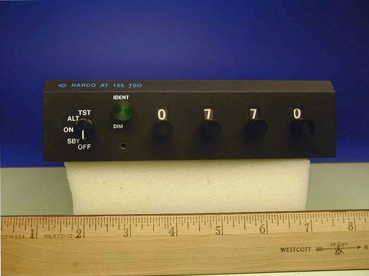
A9SAT155
Sep 02, 2002Aviation Transponder
Equipment Class
TNB - Licensed Non-Broadcast Station TransmitterA9SNAV122D
Mar 17, 1998CXX - Communications Rcvr for use w/ licensed Tx and CBs
Equipment Class
CXX - Communications Rcvr for use w/ licensed Tx and CBsA9SMK12D76014V
Aug 19, 1991TNB - Licensed Non-Broadcast Station Transmitter
Equipment Class
TNB - Licensed Non-Broadcast Station TransmitterA9SMK12D76028V
Aug 19, 1991TNB - Licensed Non-Broadcast Station Transmitter
Equipment Class
TNB - Licensed Non-Broadcast Station TransmitterA9SCOM120-20GTSO
Jul 25, 1991TNB - Licensed Non-Broadcast Station Transmitter
Equipment Class
TNB - Licensed Non-Broadcast Station Transmitter