AAL-CP-2575
Casio Communication Inc.
Click to zoom
Application Details
- Equipment Class
- DXX - Part 15 Low Power Communication Device Transmitter
- Date of Grant
- Apr 13, 2000
- Application Purpose
- Original Equipment
- Date of Application
- Mar 21, 2000
- Frequency Range
- 2402.10000000 - 2406.50000000
- Company
- Casio Communication Inc.
- Country
- United States
Documents & Files
Document Text
Text extracted from the exhibit documents filed with the FCC. Open a document above to read the original.
Users Manual
CP-2575/CP-2070 US OG Preliminary Text March 17, 2000 CP2575 M1S1 OG.doc1 Red highlight = new change Green highlight = questionable change CP-2575/CP-2070 EASY TO USE OWNER'S GUIDE 2.4 GHz CORDLESS PHONE WITH CALL WAITING CALLER ID Charge the Handset battery Before Using the Cordless Telephone The battery loses its charge during shipping and storage. Be sure to charge the battery before you use the CP- 2575/CP-2070 cordless telephone. Place the handset in the base unit. The CHARGING INDICATOR on the base will light. Leave the handset in the base unit for 12-15 hours. Optimize the 2.4 GHz Cordless Performance For maximum distance and noise free operation , place the base unit away from electrical appliances. Place the base unit in a central location with no obstructions such as walls. If you experience interference while using the handset near other electrical appliances or other cordless phone base units, move away from the electrical appliance or other cordless phone base unit and closer to the CP-2575/CP-2070 base unit. Digital Security Code The Digital Security Coding System automatically resets a new personal security code, to one of over 64,000 combinations, every time you return the CP-2575/CP-2070 handset to the base unit. (Whenever the handset is returned to the base unit, you will hear a beep.) The security code prevents unauthorized use of your telephone line, false rings and false dialing. INSTALLATION WARNING: This unit is not shippe d with the handset battery installed. Please install and charge the handse t batte ry pack be fore initial se tup and use . PLUG the CP-2575/CP-2070's telephone cord into a telephone wall jack. Plug the other end of the cord into the back of the base unit. CONNECT the AC Adapter Plug into the AC Adapter Outlet on the back of the CP-2575/CP-2070 charging cradle. LOOP the cord through the AC Adapter Cord Holder to prevent accidental disconnection. PLUG the AC Adapter into an electrical wall outlet. Place the handset (with battery pack installed) in the cradle. It may be necessary to set the TONE/PULSE SWITCH. Raise the charging cradle antenna for clear reception. INITIAL SETUP WALL/ DESK USE A wall mount bracket is included and can be installed if needed. Tightly coil the telephone cord around the four guides on the inside of the w all mounting bracket. Pull the telephone cord through the center opening on the wall mounting bracket. Refer to the drawing. The handset can be charged face out or face down, even when wall mounted. Tone/Pulse Sw itch This switch tells the CP-2575/CP-2070 to dial out with either touchtone or pulse signals to match the service you have with your local telephone company. The CP-2575/CP-2070 is shipped with the TONE/PULSE SWITCH in the TONE position. If you do not have touchtone service, set the switch to pulse on the back of the charging cradle. TONE = for Touchtone systems PULSE = for Rotary dialing or Pulse systems Ringer On/Off The CP-2575/CP-2070 is shipped with the handset RINGER ON/OFF SWITCH in the ON position and the base RINGER OFF/LOW/HIGH SWITCH in the HIGH position. You can independently set the ringers of the CP-2575/CP-2070. IMPORTANT FEATURES 2.4 GHz Hybrid Cordless Technology CP-2575/CP-2070 US OG Preliminary Text March 17, 2000 CP2575 M1S1 OG.doc2 Advanced technology provides enhanced clarity and superior reception. 2.4 GHz operates on a higher frequency than conventional 900 MHz telephones. Caller ID If you subscribe to a Caller Identification Service (available from most local telephone companies), the CP- 2575/CP-2070 can display the name and phone number of incoming calls. With the Caller ID feature, you can see who is calling before you answer a call. Call Waiting Caller ID If you subscribe to a Call Waiting Caller ID service from your local telephone company, the CP-2575/CP- 2070 can display the name and number of an incoming call while you are already talking to another party on the cordless handset. NOTE: You must order the complete package that is known as "CALL WAITING/CALLER ID" from your local telephone company. If you simply order the two services of CALL WAITING and CALLER ID you may not receive Call Waiting Caller ID service. Caller ID Memory The CP-2575/CP-2070 automatically stores the Caller ID names and numbers of the last 50 calls you have received. Modem MonitorTM Connection Protection Modem MonitorTM protects modem and fax connections when a call attempt is made from any phone that includes the Modem MonitorTM feature. It distinguishes betw een data and standard voice communication and allows for normal telephone operation. Low Cost Routing Save money on long distance calls! Intelligently selects a low cost carrier each time you dial. No programming, no sign-up or activation fee, no monthly minimum, and no long term contracts. Data Port for PC Connection Allows quick connection of portable computers, fax machines, or e-mail devices to a phone line. Just plug into the base. Supertwist Nematic (STN) LCD Advanced LCD technology in your CP-2575/CP-2070 provides clear, multi-angle viewing of caller's name and phone number if you subscribe to Caller ID service from your local telephone company. Autodial Memory Backup CASIO's memory backup system maintains up to 20 autodial names and numbers indefinitely until you erase them. This non-volatile memory does not require battery power. Charging The Battery Charge the battery for 12-15 hours before using the cordless handset for the first time. The handset is alw ays charging while it is in the charging cradle and cannot be overcharged. To charge the battery, first check the AC Adapter to see that it is connected correctly. Then, place the handset in the charging cradle. The CHARGING INDICATOR on the charging cradle lights solid to indicate that the CP-2575/CP-2070 is charging. Local Area Code Setting If you are planning to use the Caller ID features on the CP-2575/CP-2070 and you reside in a 7-digit dialing area, you may w ant to program your loc…
Text truncated - open the document above for the full version.
Block Diagram
BPF Base unit ANTMATCHING LNA MIX1st LoVCOBuff VCO LPF MCF 1st IFAMP IF & DET × 3 C.F BPF ANTMATCHING PLL × 3 PA VCOBuff LPF 3V VCO RX900MHz IF1=45MHz Lo2=44.55MHz IF2=450KHz 14.85MHz AF in RXTX +B TX SW TX2.4GMHz DETout 3.3V BPF Handset unit ANTMATCHING LNA MIX× 3 VCOBuff VCO LPF MCF 1st IFAMP IF & DET × 3 C.F BPF ANTMATCHING PLL PA VCOBuff LPF VCO IF1=45MHz Lo2=44.55MHz IF2=450KHz 14.85MHz AF in RXTX +B TX SW DETout 1st Lo RX2.4GHz TX900MHz
Schematics
A A B B C C D D E E 44 33 22 11 UNIT; R=ohm C=F L=H DRAWINGDESINGCHECKEDAPPROVED MODEL PARTS_NAME PARTS_CODE SCHEMATIC_D/G DATEFeb 29 2000 ASAHI_CORPORATION 3986-498-0-00 TP-3986(RF_MODULE_BASE) orBA4116FV V2 STB PLL_CLK TX_ SW AF_IN GND POWER DET_OUT RSSI CD PLL_DATA TP8 1 C109 3P R58 22 C16 0.047u R20 4.7 C5 22p C2 3p C3 1000P R16 4.7 R33 4.7 R1 15K L15 18n L11 22n C1 1000p C68 N.M Q1 2SC5369 12 3 45 6 T1 2 1 C110 22P C11 1000p R28 560 C88 2.5P R56 4.7K R27 33K IC2 TA31136FN 1234 1211109 5678 13141516 XINXOUTMOUTVCC RSSI IFOUT QUAD DET IFINDECFOUTFIN CD NREC VSS MIN C97 0.1u TP3 CD 1 L5 1.5n C63 22p C62 12p C98 27p C9 0.01u TP ANT CN1 CONNECTOR 1 2 3 4 5 6 7 8 9 10 1 2 3 4 5 6 7 8 9 10 L22 100n C128 0.1u L1 2.7n L18 0.56u C55 1000p C72 1u C17 0.1u C23 1000p R57 22 C74 1.5P C127 22p C126 22p C125 22p C81 3P R62 22 C78 3P L17 W/O CORE IC3 uPC2763T 6 5 4 1 2 3 VCC VSS3 OUT IN VSS1 VSS2 R49 1.5K D2 1SV278 L24 1.5n C90 1P C56 2p SF1 10K 2 3 1 C22 56p C77 220P R65 5.6K R64 100K X1 14.85M 1 2 BP1 900MHz 31 2 L25 6.8n C27 120p C87 1000p C14 10p C26 56p C13 270p R11 5.6K C104 10u C105 10u TP2 1 TP1 1 TP16 DC_OUT 1 TP11 CLK 1 TP10 DATA 1 TP9 STB 1 TP13 TX_SW 1 TP14 AF_IN 1 C47 1000p C46 1000p C70 10p R21 22 R2 100 Q9 2SC4178 2 3 1 C52 1000p R67 51 R46 1K R44 56K TP6 POWER 1 R38 2.2K L20 100n C100 1000P C108 3P C8 1000p R8 470 R7 680 L6 1.8n C65 6p C64 1p C19 220p C18 220p R12 150K CN3 2.4GHz 3 1 2 C43 1000p C67 5p C66 1p C44 1p Q2 2SC4226 2 3 1 CF1 45MHz 31 2 Q12 2SA1576 23 1 L7 1.8n C101 1u C69 1p C7 0.01u R6 22 R5 220 IC8 TK11 133S 54 123 VIN VOUT CONTVSSB.P L26 1.5n C120 2p C121 1.5P R3 22K R15 220K R4 8.2K R14 8.2K Q10 2SC4571 2 3 1 C20 1000p C15 1000p L13 0ohm C42 4700p R9 4.7 C114 0.5P C29 0.1u R17 27K C124 22P C28 0.01u C30 1000p L3 100n C60 8p C61 220p R13 4.7K C75 0.047u R43 22 R71 3.3 Q5 2SC4571 2 3 1 R63 51 C38 1000p C37 2p R26 820 R25 47K Q3 2SC4571 2 3 1 R40 820 Q8 2SC5408 12 3 45 6 R60 2.2K R4856K IC4 TK11130S 54 123 VIN VOUT CONTVSSB.P C31 1000p TC1 30p 1 2 L9 12n L8 4.7n R36 18K C111 10u C107 8P R66 100 C12 0.022u R18 8.2K Q7 2SC5065Y 2 3 1 C36 1000P L12 0.56u C51 0.22u C50 0.047u C39 5p R19 2.2K R37 39K IC1 TB31206FN 1234 1211109 5678 13141516 CP1GND1FIN1VCC1 SW XIN XOUT B0 LDCLKDATASTB VCC2 FIN2 GND2 CP2 D1 1SV278 C102 4700p C24 0.047u C76 1000p C6 1p BP2 2.4GHz 31 2 Q11 2SC5065Y 2 3 1 R53 10K C91 1000p R30 1K L14 2.2n C80 1P C40 3p R72 2.2K L10 12n C41 3p R51 15K R50 5.1K TP12 RSSI 1 C82 3P C83 1000p R52 330 R31 1K TP17 1 TP15 1 C32 47p R59 1K R24 1K R22 47K R41 680 R23 10K TP26 1 C21 10u Q4 2SC4178 2 3 1 C34 12p C95 2p C35 4700p AN1 1 CF2 450KHz 3 1 2 4 5 C96 2p R55 330 C49 0.01u C94 3p C59 22P C93 3p R54 15K C10 0ohm C57 22P L21 2.7n C53 56P C118 3p R68 22 R42 47 C117 22P C115 0.5P R61 47K IC7 uPC2762T 6 5 4 1 2 3 VCC VSS3 OUT IN VSS1 VSS2 C45 1000p R29 1K L16 W/O CORE C54 2P C85 3p R39 47K C71 1.5P
Schematics
A A B B C C D D E E 44 33 22 11 UNIT; R=ohm C=F L=H DRAWINGDESINGCHECKEDAPPROVED MODEL PARTS_NAME PARTS_CODE SCHEMATIC_D/G DATE ASAHI_CORPORATION 3987-498-0-00 TP-3987(RF_MODULE_H/S) orBA4116 FV V4 Mar_17_2000 PLL_STB PLL_CLK PLL_DATA AF_IN CD DET_OUT RSSI GND POWER TX_SW R67 820 L25 1.5n L18 1.8n R76 51 C113 1p C111 12p C118 22p C119 4p C120 5p C112 1p C110 1000pC109 7p C107 1000p C108 7p CN3 CONNECTER 1 2 3 4 5 6 7 8 9 10 R77 120 R66 68K R78 51 R72 470 R71 68K R70 470 C123 7p L7 8.2n C122 N.M L26 2.2n C121 7p C127 5P C126 1000P C129 0.5P C125 7P Q8 2SC5065Y 2 3 1 C25 1p C124 1000P C59 3P R41 22K L3 12n R42 100 C58 1000p C60 4P C61 1000p L4 4.7n BP2 900MHz 31 2 C67 1P L16 10n C75 33P C66 1P TP4 1 TP16 1 ANT 900MHz C24 0.1u C116 2P C86 3P C16 0.047u R20 4.7 R58 22 C3 1000P R16 4.7 C1 2p C104 5p L13 2.7n L6 2.2n R1 27K R33 4.7 Q1 2SC5408 12 3 45 6 C88 3P C11 1000p T1 2 1 TP6 CD 1 C97 0.1u R56 4.7K IC2 TA311 36FN 1234 1211109 5678 13141516 XINXOUTMOUTVCC RSSI IFOUT QUAD DET IFINDECFOUTFIN CD NREC VSS MIN C103 0.1u C98 27p C9 0.01u L2 3.9n C17 0.1u C23 1000p C53 1000p L23 0.56u C78 2.5P C81 2P R57 100 L20 W/O CORE C90 1P D2 1SV278 R49 2.7K C100 N.M C77 47P SF1 10K 2 3 1 C56 1p BP1 2.4GHz 31 2 R68 100K X1 14.85M 1 2 R69 5.6K C87 1000p C14 10p C27 120p L5 N.M C26 56p C115 10u R11 5.6K C13 270p C101 N.M TP10 STB 1 TP11 DATA 1 TP12 CLK 1 C46 1000p C47 1000p TP15 AF_IN 1 TP14 TX_SW 1 C52 1000p Q9 2SC4178 2 3 1 R2 180 C70 27p TP8 POWER 1 TP7 DET_OUT 1 R44 56K R46 1.5K TP9 GND 1 R5 1K R38 2.2K C19 220p CF1 45MHz 31 2 Q6 2SA1576 23 1 R12 150K C18 220p R79 220K R3 150K R4 470 C22 1000P C73 0ohm C20 1000p Q10 2SC4571 2 3 1 R14 8.2K C15 1000p C29 0.1u R17 27K R9 4.7 C30 1000p C28 0.01u R13 4.7K C44 1000p Q3 2SC4571 2 3 1 R25 100K R26 560 C37 2p C31 1000p R4856K R60 2.2K R40 220 L1 N.M TC1 30p 1 2 R36 18K L9 2.7n C51 0.22u Q7 2SC5065Y 2 3 1 C12 0.022u R18 10K C50 0.047u R37 33K R19 2.2K C43 1.5p C76 1000p C5 1000P C89 1.5p D1 1SV278 C91 1000p R30 1K R53 8.2K Q11 2SC5065Y 2 3 1 C41 1p R75 2.2K C40 1.5p C80 1P C82 2P TP13 RSSI 1 R50 10K R51 15K R52 330 C83 1000p TP1 1 R31 1K R24 1K R59 1K C32 47p TP2 1 R22 47K TP3 1 R34 10K R35 1.5K C21 10u Q4 2SC4178 2 3 1 C95 3p C34 12p C96 3p CF2 450KHz 3 1 2 4 5 C35 4700p R55 270 C94 3p L27 22n C49 0.01u R54 22K C93 3p CN2 2.4GHz 3 1 2 R29 1K C45 1000p C57 1P L21 W/O CORE C106 0.5P R39 47K C85 3p Q2 2SC5408 12 3 45 6 C102 N.M C4 7p C105 1p C62 7P C7 1000P C63 7P L11 2.7n C2 1000P C8 6P C6 1000P L14 0.82u IC1TB312 06FN 1234 1211109 5678 13141516 CP1GND1FIN1VCC1 SWXIN XOUT B0 LDCLKDATASTB VCC2 FIN2 GND2 CP2 L22 0.82u C71 12P C10 1000P Q14 2SC5408 12 3 45 6 Q13 2SC5369 12 3 45 6 Q5 2SC5369 12 3 45 6 C114 10u L19 1.8n
Test Report
FCC ID: AAL-CP-2575 Report Number: B00310D1 114 OLINDA DRIVE, BREA, CALIFORNIA 92823 PHONE: (714) 579-0500 FAX: (714) 579-1850 Page 1 of 16 FCC PART 15, SUBPART C TEST METHOD: ANSI C63.4-1992 for 2.4 GHz / 900 MHz CORDLESS PHONE Model: CP-2575 Prepared for CASIO COMMUNICATIONS, INC. PO BOX 2914 TORRANCE, CALIFORNIA 90509-2914 COMPATIBLE ELECTRONICS INC. 114 OLINDA DRIVE BREA, CALIFORNIA 92823 (714) 579-0500 DATE: MARCH 23, 2000 REPORT APPENDICES TOTAL BODY A B C D PAGES 16 2 3 14 30 64 This report shall not be reproduced except in full, without the written approval of Compatible Electronics. FCC ID: AAL-CP-2575 Report Number: B00310D1 114 OLINDA DRIVE, BREA, CALIFORNIA 92823 PHONE: (714) 579-0500 FAX: (714) 579-1850 Page 2 of 16 TABLE OF CONTENTS Section / Title PAGE GENERAL REPORT SUMMARY 4 1. PURPOSE 5 2. ADMINISTRATIVE DATA 6 2.1 Location of Testing 6 2.2 Traceability Statement 6 2.3 Cognizant Personnel 6 2.4 Date Test Sample was Received 6 2.5 Disposition of the Test Sample 6 2.6 Abbreviations and Acronyms 6 3. APPLICABLE DOCUMENTS 7 4. Description of Test Configuration 8 4.1 Description of Test Configuration - EMI 8 4.1.1 Cable Construction and Termination 9 5. LISTS OF EUT, ACCESSORIES AND TEST EQUIPMENT 10 5.1 EUT and Accessory List 10 5.2 EMI Test Equipment 11 6. TEST SITE DESCRIPTION 12 6.1 Test Facility Description 12 6.2 EUT Mounting, Bonding and Grounding 12 7. Test Procedures 13 7.1 RF Emissions 13 7.1.1 Conducted Emissions Test 13 7.1.2 Radiated Emissions (Spurious and Harmonics) Test 14 7.2 RF Band Edges 15 8. CONCLUSIONS 16 FCC ID: AAL-CP-2575 Report Number: B00310D1 114 OLINDA DRIVE, BREA, CALIFORNIA 92823 PHONE: (714) 579-0500 FAX: (714) 579-1850 Page 3 of 16 LIST OF APPENDICES APPENDIX TITLE A Modifications to the EUT B Additional Models Covered Under this Report C Diagrams, Charts and Photos • Test Setup Diagrams • Radiated and Conducted Emissions Photos • Antenna and Effective Gain Factors D Data Sheets E Channel Number and Frequencies of the EUT LIST OF FIGURES FIGURE TITLE 1 Conducted Emissions Test Setup 2 Plot Map And Layout of Test Site 3 Processing Gain Setup FCC ID: AAL-CP-2575 Report Number: B00310D1 114 OLINDA DRIVE, BREA, CALIFORNIA 92823 PHONE: (714) 579-0500 FAX: (714) 579-1850 Page 4 of 16 GENERAL REPORT SUMMARY This electromagnetic emission test report is generated by Compatible Electronics Inc., which is an independent testing and consulting firm. The test report is based on testing performed by Compatible Electronics personnel according to the measurement procedures described in the test specifications given below and in the "Test Procedures" section of this report. The measurement data and conclusions appearing herein relate only to the sample tested and this report may not be reproduced in any form unless done so in full with the written permission of Compatible Electronics. This report must not be used to claim product endorsement by NVLAP or any other agency of the U.S. Government. Device Tested: 2.4 GHz / 900 MHz Cordless Phone Model: CP-2575 S/N: N/A Modifications: The EUT was not modified during the testing. Manufacturer: Casio Communications, Inc. P.O. Box 2914 Torrance, California 90509-9214 Test Date: March 10, 2000 Test Specifications: EMI requirements FCC Title 47, Part 15 Subpart B; and Subpart C, sections 15.205, 15.207, 15.209, and 15.249 Test Procedure: ANSI C63.4: 1992 Test Deviations: The test procedure was not deviated from during the testing. SUMMARY OF TEST RESULTS TEST DESCRIPTION RESULTS 1 Conducted RF Emissions, 450 kHz - 30 MHz Complies with the limits of CFR Title 47, Part 15, Subpart C, section 15.207 2 Radiated RF Emissions, 10 kHz - 25000 MHz Complies with the limits of CFR Title 47, Part 15, Subpart C, sections 15.205 and 15.249 FCC ID: AAL-CP-2575 Report Number: B00310D1 114 OLINDA DRIVE, BREA, CALIFORNIA 92823 PHONE: (714) 579-0500 FAX: (714) 579-1850 Page 5 of 16 1. PURPOSE This document is a qualification test report based on the Electromagnetic Compatibility (EMC) tests performed on the 2.4 GHz / 900 MHz Cordless Phone Model: CP-2575. The EMI measurements were performed according to the measurement procedure described in ANSI C63.4: 1992. The tests were performed in order to determine whether the electromagnetic emissions from the equipment under test, referred to as EUT hereafter, are within the specification limits defined by CFR Title 47, Part 15, Subpart B; and Subpart C, sections 15.205, 15.207, and 15.249. FCC ID: AAL-CP-2575 Report Number: B00310D1 114 OLINDA DRIVE, BREA, CALIFORNIA 92823 PHONE: (714) 579-0500 FAX: (714) 579-1850 Page 6 of 16 2. ADMINISTRATIVE DATA 2.1 Location of Testing The EMI tests described herein were performed at the test facility of Compatible Electronics, 114 Olinda Drive, Brea, California 92823. 2.2 Traceability Statement The calibration certificates of all test equipment used during the test are on file at the location of the test. The calibration is traceable to the National Institute of Standards and Technology (NIST). 2.3 Cognizant Personnel Casio Communications, Inc. Lananh T. Tran Compliance Engineer Compatible Electronics Inc. Kyle Fujimoto Test Engineer Scott McCutchan Lab Manager 2.4 Date Test Sample was Received The test sample was received on March 10, 2000. 2.5 Disposition of the Test Sample The test sample was returned to Casio Communications, Inc. on March 23, 2000. 2.6 Abbreviations and Acronyms The following abbreviations and acronyms may be used in this document. RF Radio Frequency EMI Electromagnetic Interference EUT Equipment Under Test P/N Part Number S/N Serial Number HP Hewlett Packard ITE Information Technology Equipment CML Corrected Meter Limit LISN Line Impedance Stabilization Network NCR No Calibration Required H/S Handset Station B/S Base Station FCC ID: AAL-CP-2575 Report Number: B00310D1 114 OLINDA DRIVE, BREA, CALIFORNIA 92823 PHONE: (714) 579-0500 FAX: (714) 579-1850 Page 7 of 16 3. APPLICABLE DOCUMENTS The following documents are referenced or used in…
Text truncated - open the document above for the full version.
Contact Information
Applicant
Kevin Mullally(Engineering Manager)
310 618-9910Fax: 310 618-6821
Test Firm
Compatible ElectronicsScott McCutchan
714-579-0500Fax: 714-579-1850
Technical Specifications
| # | Rule Parts | Frequency Range | Power Output | Tolerance |
|---|---|---|---|---|
| 2 | 15C | 2.40 GHz - 2.41 GHz | - | % |
Other Applications from Casio Communication Inc.

AAL-TC-1475
Oct 25, 2000900MHz Cordless Phone w/Digital Answering Machine
Equipment Class
DXT - Part 15 Low Power Transceiver, Rx Verified
AAL-TC-2775
Jun 22, 20002.4 GHz / 900 MHz Cordless Phone
Equipment Class
DXT - Part 15 Low Power Transceiver, Rx Verified
AAL-CP750
Sep 30, 1999ETS - Part 15 Cordless Telephone System
Equipment Class
ETS - Part 15 Cordless Telephone System
AAL-TC-920
May 23, 1999900 MHz Cordless Telephone
Equipment Class
DXT - Part 15 Low Power Transceiver, Rx Verified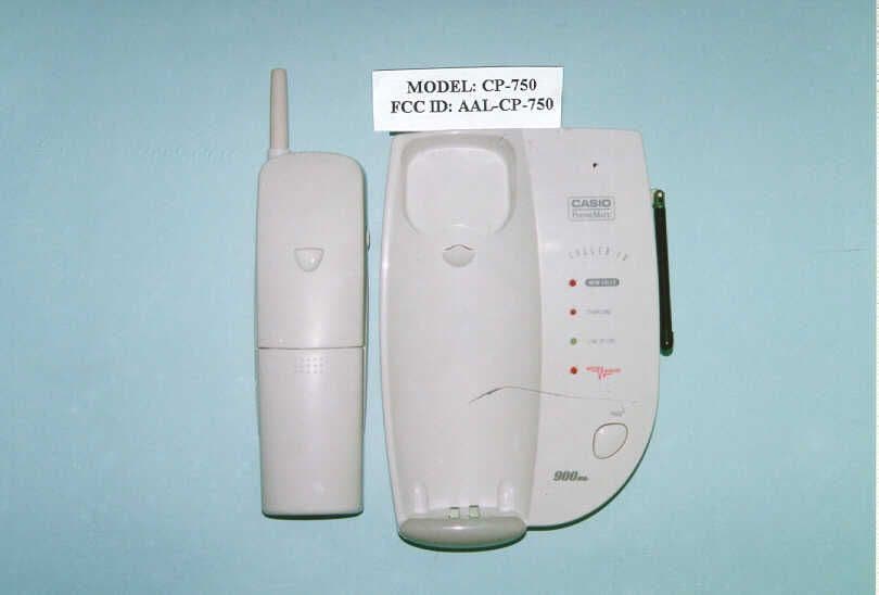
AAL-CP-750
May 23, 1999900 MHz 40 Channel Analog Cordless Telephone
Equipment Class
DXT - Part 15 Low Power Transceiver, Rx Verified