ACJ-DMC-TZ50Digital Still Camera
Panasonic Corporation of North America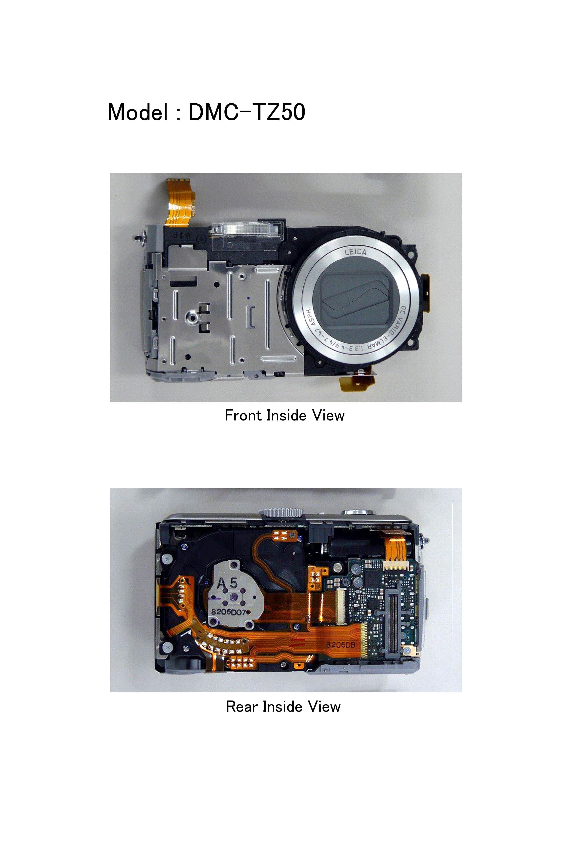
Click to zoom
Application Details
- Equipment Class
- DTS - Digital Transmission System
- Date of Grant
- Apr 02, 2008
- Application Purpose
- Original Equipment
- Date of Application
- Apr 01, 2008
- Equipment Note
- Digital Still Camera
- Frequency Range
- 2412.00000000 - 2462.00000000
- Country
- United States
Documents & Files
Document Text
Text extracted from the exhibit documents filed with the FCC. Open a document above to read the original.
Users Manual
For USA assistance, please call: 1-800-211-Pana(7262) or, contact us via the web at: http://www.panasonic.com/contactinfo For Canadian assistance, please call: 1-800-99-LUMIX (1-800-995-8649) or send e-mail to: [email protected] VQT1P79-3 PCP Before connecting, operating or adjusting this product, please read the instructions completely. Operating Instructions Digital Camera Model No. DMC-TZ5 DMC-TZ4 DMC-TZ50 2 VQT1P79VQT1P79 3 A lithium ion/polymer battery that is recyclable powers the product you have purchased. Please call 1-800-8-BATTERY for information on how to recycle this battery. Dear Customer, Thank you for choosing Panasonic! You have purchased one of the most sophisticated and reliable products on the market today. Used properly, we’re sure it will bring you and your family years of enjoyment. Please take time to fill in the information below. The serial number is on the tag located on the underside of your Camera. Be sure to retain this manual as your convenient Camera information source. Model No. Serial No. Information for Your Safety WARNING: TO REDUCE THE RISK OF FIRE, ELECTRIC SHOCK OR PRODUCT DAMAGE, • DO NOT EXPOSE THIS APPARATUS TO RAIN, MOISTURE, DRIPPING OR SPLASHING AND THAT NO OBJECTS FILLED WITH LIQUIDS, SUCH AS VASES, SHALL BE PLACED ON THE APPARATUS. • USE ONLY THE RECOMMENDED ACCESSORIES. • DO NOT REMOVE THE COVER (OR BACK); THERE ARE NO USER SERVICEABLE PARTS INSIDE. REFER SERVICING TO QUALIFIED SERVICE PERSONNEL. Carefully observe copyright laws. Recording of pre-recorded tapes or discs or other published or broadcast material for purposes other than your own private use may infringe copyright laws. Even for the purpose of private use, recording of certain material may be restricted. THE SOCKET OUTLET SHALL BE INSTALLED NEAR THE EQUIPMENT AND SHALL BE EASILY ACCESSIBLE. CAUTION Danger of explosion if battery is incorrectly replaced. Replace only with the same or equivalent type recommended by the manufacturer. Dispose of used batteries according to the manufacturer’s instructions. Warning Risk of fire, explosion and burns. Do not disassemble, heat above 60 °C (140 °F) or incinerate. Product Identification Marking is located on the bottom of units. THE FOLLOWING APPLIES ONLY IN THE U.S.A. FCC Note: (U.S. only) This equipment has been tested and found to comply with the limits for a Class B digital device, pursuant to Part 15 of the FCC Rules. These limits are designed to provide reasonable protection against harmful interference in a residential installation. This equipment generates, uses, and can radiate radio frequency energy and, if not installed and used in accordance with the instructions, may cause harmful interference to radio communications. However, there is no guarantee that interference will not occur in a particular installation. If this equipment does cause harmful interference to radio or television reception, which can be determined by turning the equipment off and on, the user is encouraged to try to correct the interference by one or more of the following measures: • Reorient or relocate the receiving antenna. • Increase the separation between the equipment and receiver. • Connect the equipment into an outlet on a circuit different from that to which the receiver is connected. • Consult the dealer or an experienced radio/TV technician for help. FCC Caution: To assure continued compliance, follow the attached installation instructions and use only shielded interface cables with ferrite core when connecting to computer or peripheral devices. Any changes or modifications not expressly approved by the party responsible for compliance could void the user’s authority to operate this equipment. Declaration of Conformity Trade Name: Panasonic Model No.: DMC-TZ5 DMC-TZ4 DMC-TZ50 Responsible party: Panasonic Corporation of North America One Panasonic Way, Secaucus, NJ 07094 Support Contact: Panasonic Consumer Electronics Company 1-800-211-PANA (7262) This device complies with Part 15 of the FCC Rules. Operation is subject to the following two conditions: (1) This device may not cause harmful interference, and (2) this device must accept any interference received, including interference that may cause undesired operation. DMC-TZ5 DMC-TZ4 DMC-TZ50 THE FOLLOWING APPLIES ONLY IN CANADA This Class B digital apparatus complies with Canadian ICES-003. 4 VQT1P79VQT1P79 5 1/9 100–0001100–0001 1/9 10:00MAR.15.200810:00MAR.15.2008 The battery is not charged when the camera is shipped. Charge the battery and set the clock before use. When you do not use the card (sold separately), you can record or play back pictures on the built-in memory (P.18). Quick start guide -If you see this symbol- Information on Disposal in other Countries outside the European Union This symbol is only valid in the European Union. If you wish to discard this product, please contact your local authorities or dealer and ask for the correct method of disposal. About the battery pack Battery pack (Lithium ion battery pack) • Use the specified unit to recharge the battery pack. • Do not use the battery pack with equipment other than the specified unit. • Do not get dirt, sand, liquids, or other foreign matter on the terminals. • Do not touch the plug terminals (+ and −) with metal objects. • Do not disassemble, remodel, heat or throw into fire. If any electrolyte should come into contact with your hands or clothes, wash it off thoroughly with water. If any electrolyte should come into contact with your eyes, never rub the eyes. Rinse eyes thoroughly with water, and then consult a doctor. About the battery charger CAUTION! DO NOT INSTALL OR PLACE THIS UNIT IN A BOOKCASE, BUILT- IN CABINET OR IN ANOTHER CONFINED SPACE. ENSURE THE UNIT IS WELL VENTILATED. TO PREVENT RISK OF ELECTRIC SHOCK OR FIRE HAZARD DUE TO OVERHEATING, ENSURE THAT CURTAINS AND ANY OTHER MATERIALS DO NOT OBSTRUCT THE VENTILATION VENTS. Battery charger This battery charger operates on AC between 110 V and 240 V.…
Text truncated - open the document above for the full version.
Users Manual
W I R E L E S S Before connecting, operating or adjusting this product, please read the instructions completely. P For USA assistance, please call: 1-800-211-Pana(7262) or, contact us via the web at: http://www.panasonic.com/contactinfo VQT1R37 Model No. DMC-TZ50 Operating Instructions Digital Camera Wi-Fi mode Panasonic Consumer Electronics Company, Division of Panasonic Corporation of North America One Panasonic Way, Secaucus, NJ 07094 Panasonic Puerto Rico, Inc. Ave. 65 de Infantería, Km. 9.5, San Gabriel Industrial Park, Carolina, Puerto Rico 00985 Panasonic Canada Inc. 5770 Ambler Drive, Mississauga, Ontario, L4W 2T3 © 2008 Matsushita Electric Industrial Co., Ltd. P VQT1R37 M0308KZ0 23 FCC RF Exposure Statement The available scientific evidence does not show that any health problems are associated with using low power wireless devices. There is no proof, however, that these low power wireless devices are absolutely safe. Low power wireless devices emit low levels of radio frequency energy (RF) in the microwave range while being used. Whereas high levels of RF can produce health effects (by heating tissue), exposure to low-level RF that does not produce heating effects causes no known adverse health effects. Many studies of low-level RF exposures have not found any biological effects. Some studies have suggested that some biological effects might occur, but such findings have not been confirmed by additional research. DMC-TZ50 has been tested and found to comply with FCC radiation exposure limits set forth for an uncontrolled equipment and meets the FCC radio frequency (RF) Exposure Guidelines in Supplement C to OET65. Please refer to the SAR test report that was uploaded at FCC website. This device should not be co-located or operated in conjunction with any other antenna or transmitter. FCC Note: This equipment has been tested and found to comply with the limits for a Class B digital device, pursuant to Part 15 of the FCC Rules. These limits are designed to provide reasonable protection against harmful interference in a residential installation. This equipment generates, uses and can radiate radio frequency energy and, if not installed and used in accordance with the instructions, may cause harmful interference to radio communications. However, there is no guarantee that interference will not occur in a particular installation. If this equipment does cause harmful interference to radio or television reception, which can be determined by turning the equipment off and on, the user is encouraged to try to correct the interference by one or more of the following measures: • Reorient or relocate the receiving antenna. • Increase the separation between the equipment and receiver. • Connect the equipment into an outlet on a circuit different from that to which the receiver is connected. • Consult the dealer or an experienced radio/TV technician for help. FCC caution: To maintain compliance with FCC regulations, shielded interface cables must be used with this equipment. Operation with non-approved equipment or unshielded cables may result in interference to radio and TV reception. Any changes or modifications not approved by the party responsible for compliance could void the user’s authority to operate this equipment. This device complies with Part 15 of the FCC Rules. Operation is subject to the following two conditions: (1) This device may not cause harmful interference, and (2) this device must accept any interference received, including interference that may cause undesired operation. The unit which can be connected to PC or which has a USB terminal: You have to indicate the following before Responsible Party. Declaration of Conformity Trade Name: Panasonic Model No.: DMC-TZ50 Responsible Party: Panasonic Corporation of North America One Panasonic Way Secaucus, NJ 07094 Support Contact: Panasonic Consumer Electronics Company Telephone No.: 1-800-211-PANA (7262) 45 Upload pictures to your web album and view with your friends ‘Picasa Web Albums’ is an online album service provided by Google. Upload the pictures you have taken to your web album, using your camera’s Wi-Fi mode. You can share your pictures by sending your web album URL to your friends. You can also change your web album’s privacy setting on your computer between ‘Only people I have informed can view (Private)’ and ‘Anyone can view (Public)’. For more details, see the following website. http://xxxxxxxxxx (correct as of April 2008) Upload your pictures at home or on the move You can access ‘Picasa Web Albums’ using any of the following. Using T-Mobile HotSpots around town T-Mobile HotSpots can be found in stores and in areas such as stations and airports. A valid T-Mobile account (user ID and password) is needed for this service (charges apply). (A T-Mobile account is preset to your camera, but the validity period is limited.) For more details, see the following website. http://hotspot.t-mobile.com/ (Address correct as of April 2008) Using at home with a T-Mobile@HOME-compatible router Appropriate settings (P.26) will need to be made on your camera. Using access points (home, external) other than T-Mobile Appropriate settings (P.28) will need to be made on your camera when you sign up to other services. (Contact the appropriate operating companies for details on individual services.) ‘Picasa Web Albums’ and ‘T-Mobile’ services may be altered at any time without prior notification. Take pictures Upload Access using T-Mobile HotSpots around town or using T-Mobile@HOME in your home. Picasa Web Albums Send pictures to your web album (upload). Check your uploaded pictures (pictures can also be deleted) Send your web album’s URL to your mobile telephone or etc. URL View together Add a message and send your web album’s URL to your friends and family 67 INDEXMain Operations Before use Main Operations .............................6 Before Using ...................................8 Wireless LAN function ..................9• Basics Wi…
Text truncated - open the document above for the full version.
ID Label/Location Info
Label Format Label Location
RF Exposure Info
Attachment 1 – System Validation Plots JAPAN QUALITY ASSURANCE ORGANIZATION Date/Time: 2008/03/10 9:37:56 Test Laboratory: JAPAN QUALITY ASSURANCE ORGANIZATION System Validation (Body 2450MHz) DUT: Dipole 2450 MHz; Type: D2450V2; Serial: 714 Communication System: CW; Frequency: 2450 MHz;Duty Cycle: 1:1 Medium: M2450 Medium parameters used: f = 2450 MHz; σ = 2.03 mho/m; ε r = 51.4; ρ = 1000 kg/m 3 Phantom section: Flat Section Measurement Standard: DASY4 (High Precision Assessment) DASY4 Configuration: zProbe: ET3DV6 - SN1679; ConvF(4.09, 4.09, 4.09); Calibrated: 2007/11/15 zSensor-Surface: 4mm (Mechanical And Optical Surface Detection) zElectronics: DAE3 Sn508; Calibrated: 2007/11/07 zPhantom: SAM 1200; Type: QD 000 P40 CA; Serial: 1200 zMeasurement SW: DASY4, V4.7 Build 44; Postprocessing SW: SEMCAD, V1.8 Build 171 Antenna Input Power 250 mW/Area Scan (5x5x1): Measurement grid: dx=20mm, dy=20mm Maximum value of SAR (measured) = 16.6 mW/g Antenna Input Power 250 mW/Zoom Scan (5x5x7)/Cube 0: Measurement grid: dx=8mm, dy=8mm, dz=5mm Reference Value = 95.7 V/m; Power Drift = -0.053 dB Peak SAR (extrapolated) = 31.7 W/kg SAR(1 g) = 14.4 mW/g; SAR(10 g) = 6.63 mW/g Maximum value of SAR (measured) = 16.2 mW/g 0 dB = 16.2mW/g JAPAN QUALITY ASSURANCE ORGANIZATION
RF Exposure Info
Attachment 2 – SAR Test Plots JAPAN QUALITY ASSURANCE ORGANIZATION Date/Time: 2008/03/10 13:38:57 Test Laboratory: JAPAN QUALITY ASSURANCE ORGANIZATION 802.11b 1ch (2412MHz) DUT: Digital Camera; Type: DMC-TZ50; Serial: TZ50 000083 Communication System: WLAN; Frequency: 2412 MHz;Duty Cycle: 1:1 Medium: M2450 Medium parameters used: f = 2412 MHz; σ = 2.03 mho/m; ε r = 51.4; ρ = 1000 kg/m 3 Phantom section: Flat Section Measurement Standard: DASY4 (High Precision Assessment) DASY4 Configuration: zProbe: ET3DV6 - SN1679; ConvF(4.09, 4.09, 4.09); Calibrated: 2007/11/15 zSensor-Surface: 4mm (Mechanical And Optical Surface Detection) zElectronics: DAE3 Sn508; Calibrated: 2007/11/07 zPhantom: SAM 1200; Type: QD 000 P40 CA; Serial: 1200 zMeasurement SW: DASY4, V4.7 Build 44; Postprocessing SW: SEMCAD, V1.8 Build 171 Body-worn/Area Scan (7x9x1): Measurement grid: dx=15mm, dy=15mm Maximum value of SAR (measured) = 0.735 mW/g Body-worn/Zoom Scan (5x5x7)/Cube 0: Measurement grid: dx=8mm, dy=8mm, dz=5mm Reference Value = 17.7 V/m; Power Drift = -0.010 dB Peak SAR (extrapolated) = 2.76 W/kg SAR(1 g) = 1.04 mW/g; SAR(10 g) = 0.389 mW/g Maximum value of SAR (measured) = 1.20 mW/g 0 dB = 1.20mW/g JAPAN QUALITY ASSURANCE ORGANIZATION Date/Time: 2008/03/10 13:50:26 Test Laboratory: JAPAN QUALITY ASSURANCE ORGANIZATION 802.11b 1ch (2412MHz) DUT: Digital Camera; Type: DMC-TZ50; Serial: TZ50 000083 Communication System: WLAN; Frequency: 2412 MHz;Duty Cycle: 1:1 Medium: M2450 Medium parameters used: f = 2412 MHz; σ = 2.03 mho/m; ε r = 51.4; ρ = 1000 kg/m 3 Phantom section: Flat Section Measurement Standard: DASY4 (High Precision Assessment) DASY4 Configuration: zProbe: ET3DV6 - SN1679; ConvF(4.09, 4.09, 4.09); Calibrated: 2007/11/15 zSensor-Surface: 4mm (Mechanical And Optical Surface Detection) zElectronics: DAE3 Sn508; Calibrated: 2007/11/07 zPhantom: SAM 1200; Type: QD 000 P40 CA; Serial: 1200 zMeasurement SW: DASY4, V4.7 Build 44; Postprocessing SW: SEMCAD, V1.8 Build 171 Body-worn/Z Scan (1x1x45): Measurement grid: dx=20mm, dy=20mm, dz=2.5mm Maximum value of SAR (measured) = 1.21 mW/g JAPAN QUALITY ASSURANCE ORGANIZATION Date/Time: 2008/03/10 11:29:37 Test Laboratory: JAPAN QUALITY ASSURANCE ORGANIZATION 802.11b 6ch (2437MHz) DUT: Digital Camera; Type: DMC-TZ50; Serial: TZ50 000083 Communication System: WLAN; Frequency: 2437 MHz;Duty Cycle: 1:1 Medium: M2450 Medium parameters used: f = 2437 MHz; σ = 2.03 mho/m; ε r = 51.4; ρ = 1000 kg/m 3 Phantom section: Flat Section Measurement Standard: DASY4 (High Precision Assessment) DASY4 Configuration: zProbe: ET3DV6 - SN1679; ConvF(4.09, 4.09, 4.09); Calibrated: 2007/11/15 zSensor-Surface: 4mm (Mechanical And Optical Surface Detection) zElectronics: DAE3 Sn508; Calibrated: 2007/11/07 zPhantom: SAM 1200; Type: QD 000 P40 CA; Serial: 1200 zMeasurement SW: DASY4, V4.7 Build 44; Postprocessing SW: SEMCAD, V1.8 Build 171 Body-worn/Area Scan (7x9x1): Measurement grid: dx=15mm, dy=15mm Maximum value of SAR (measured) = 0.349 mW/g Body-worn/Zoom Scan (5x5x7)/Cube 0: Measurement grid: dx=8mm, dy=8mm, dz=5mm Reference Value = 12.8 V/m; Power Drift = -0.185 dB Peak SAR (extrapolated) = 1.52 W/kg SAR(1 g) = 0.560 mW/g; SAR(10 g) = 0.206 mW/g Maximum value of SAR (measured) = 0.718 mW/g 0 dB = 0.718mW/g JAPAN QUALITY ASSURANCE ORGANIZATION Date/Time: 2008/03/10 13:22:39 Test Laboratory: JAPAN QUALITY ASSURANCE ORGANIZATION 802.11b 11ch (2462MHz) DUT: Digital Camera; Type: DMC-TZ50; Serial: TZ50 000083 Communication System: WLAN; Frequency: 2462 MHz;Duty Cycle: 1:1 Medium: M2450 Medium parameters used: f = 2462 MHz; σ = 2.03 mho/m; ε r = 51.4; ρ = 1000 kg/m 3 Phantom section: Flat Section Measurement Standard: DASY4 (High Precision Assessment) DASY4 Configuration: zProbe: ET3DV6 - SN1679; ConvF(4.09, 4.09, 4.09); Calibrated: 2007/11/15 zSensor-Surface: 4mm (Mechanical And Optical Surface Detection) zElectronics: DAE3 Sn508; Calibrated: 2007/11/07 zPhantom: SAM 1200; Type: QD 000 P40 CA; Serial: 1200 zMeasurement SW: DASY4, V4.7 Build 44; Postprocessing SW: SEMCAD, V1.8 Build 171 Body-worn/Area Scan (7x9x1): Measurement grid: dx=15mm, dy=15mm Maximum value of SAR (measured) = 0.140 mW/g Body-worn/Zoom Scan (5x5x7)/Cube 0: Measurement grid: dx=8mm, dy=8mm, dz=5mm Reference Value = 8.13 V/m; Power Drift = 0.067 dB Peak SAR (extrapolated) = 0.782 W/kg SAR(1 g) = 0.289 mW/g; SAR(10 g) = 0.104 mW/g Maximum value of SAR (measured) = 0.395 mW/g 0 dB = 0.395mW/g JAPAN QUALITY ASSURANCE ORGANIZATION Date/Time: 2008/03/10 12:48:22 Test Laboratory: JAPAN QUALITY ASSURANCE ORGANIZATION 802.11g 6ch (2437MHz) DUT: Digital Camera; Type: DMC-TZ50; Serial: TZ50 000083 Communication System: WLAN; Frequency: 2437 MHz;Duty Cycle: 1:1 Medium: M2450 Medium parameters used: f = 2437 MHz; σ = 2.03 mho/m; ε r = 51.4; ρ = 1000 kg/m 3 Phantom section: Flat Section Measurement Standard: DASY4 (High Precision Assessment) DASY4 Configuration: zProbe: ET3DV6 - SN1679; ConvF(4.09, 4.09, 4.09); Calibrated: 2007/11/15 zSensor-Surface: 4mm (Mechanical And Optical Surface Detection) zElectronics: DAE3 Sn508; Calibrated: 2007/11/07 zPhantom: SAM 1200; Type: QD 000 P40 CA; Serial: 1200 zMeasurement SW: DASY4, V4.7 Build 44; Postprocessing SW: SEMCAD, V1.8 Build 171 Body-worn/Area Scan (7x9x1): Measurement grid: dx=15mm, dy=15mm Maximum value of SAR (measured) = 0.198 mW/g Body-worn/Zoom Scan (5x5x7)/Cube 0: Measurement grid: dx=8mm, dy=8mm, dz=5mm Reference Value = 10.2 V/m; Power Drift = -0.175 dB Peak SAR (extrapolated) = 1.18 W/kg SAR(1 g) = 0.422 mW/g; SAR(10 g) = 0.153 mW/g Maximum value of SAR (measured) = 0.545 mW/g 0 dB = 0.545mW/g JAPAN QUALITY ASSURANCE ORGANIZATION
RF Exposure Info
JAPAN QUALITY ASSURANCE ORGANIZATION Attachment 3 – Dosimetric E-Field Probe – ET3DV6, S/N: 1679 Calibration Data
RF Exposure Info
JAPAN QUALITY ASSURANCE ORGANIZATION Attachment 4 – System Validation Dipole – D2450V2, S/N: 714 Calibration Data
RF Exposure Info
JAPAN QUALITY ASSURANCE ORGANIZATION Page 1 of 21 Technical document No. 23163-0701 JQA File No. : KL80070586R Issue Date : March 24, 2008 TEST REPORT (SAR EVALUATION) APPLICANT : Matsushita Electric Industrial Co., Ltd. Network Business Group ADDRESS : 1-15 Matsuo-cho, Kadoma City, Osaka 571-8504, Japan PRODUCTS : Digital Camera MODEL NO. : DMC-TZ50 SERIAL NO. : TZ50 000083 FCC ID : ACJ-DMC-TZ50 TEST STANDARD : FCC/OET Bulletin 65 Supplement C (Edition 01-01) TESTING LOCATION : Japan Quality Assurance Organization KITA-KANSAI Testing Center 1-7-7, Ishimaru, Minoh-shi, Osaka 562-0027, Japan TEST RESULTS : Passed DATE OF TEST : March 10, 2008 This report must not used by the client to claim product endorsement by NVLAP or Yuichi Fukumoto NIST or any agency of the U.S. Government. Manager Japan Quality Assurance Organization KITA-KANSAI Testing Center Testing Dept. EMC Division NVLAP LAB CODE 200191-0 1-7-7, Ishimaru, Minoh-shi, Osaka 562-0027, Japan ● The measurement values stated in Test Report was made with traceable to National Institute of Advanced Industrial Science and Technology (AIST) of Japan, National Institute of Information and Communications Technology (NICT) of Japan , and Laboratory for EMF and Microwave Electronics at the Swiss Federal Institute of Technology (ETH) in Zürich, Switzerland. ● The applicable standard, testing condition and testing method which were used for the tests are based on the request of the applicant. ● The test results presented in this report relate only to the offered test sample. ● The contents of this test report cannot be used for the purposes, such as advertisement for consumers. ● This test report shall not be reproduced except in full without the written approval of JQA. JAPAN QUALITY ASSURANCE ORGANIZATION JQA File No. : KL80070586R Issue Date : March 24, 2008 Model No. : DMC-TZ50 FCC ID : ACJ-DMC-TZ50 Standard : FCC/OET Bulletin 65 Supplement C (Edition 01-01) Page 2 of 21 Technical document No. 23163-0701 TABLE OF CONTENTS Page Documentation ................................................................................................................................................. 3 1 Test Regulation.....................................................................................................................................3 2 Test Location.........................................................................................................................................3 3 Recognition of Test Laboratory............................................................................................................3 4 Description of the Equipment Under Test..........................................................................................4 5 Measurement System Diagram............................................................................................................5 6 System Components..............................................................................................................................6 7 Measurement Process...........................................................................................................................8 8 Measurement Uncertainties.................................................................................................................9 9 Equipment Under Test Modification.................................................................................................10 10 Responsible Party................................................................................................................................10 11 Deviation from Standard....................................................................................................................10 12 Test Results.........................................................................................................................................11 13 Summary..............................................................................................................................................12 14 Test Arrangement...............................................................................................................................13 15 Procedures used to Establish Test Signal.........................................................................................15 Appendix A: Test Data ................................................................................................................................... 17 Appendix B: Test Instruments....................................................................................................................... 20 Appendix C: Attachments .............................................................................................................................. 21 DEFINITIONS FOR ABBREVIATION AND SYMBOLS USED IN THIS TEST REPORT “EUT” means Equipment Under the Test. “AE” means Associated Equipment. “N/A” means that Not Applicable. “N/T” means that Not Tested. - indicates that the listed condition, standard or equipment is applicable for this report. - indicates that the listed condition, standard or equipment is not applicable for this report. JAPAN QUALITY ASSURANCE ORGANIZATION JQA File No. : KL80070586R Issue Date : March 24, 2008 Model No. : DMC-TZ50 FCC ID : ACJ-DMC-TZ50 Standard : FCC/OET Bulletin 65 Supplement C (Edition 01-01) Page 3 of 21 Technical document No. 23163-0701 Documentation 1 Test Regulation Applied Standard : FCC/OET Bulletin 65 Supplement C (Edition 01-01) Evaluating Compliance with FCC Guidelines for Human Exposure to Radio- frequency Electromagnetic Fields Additional Information for Evaluating Compliance of Mobile and Portable Devices with FCC Limits for Human Exposure to Radiofrequency Emissions Test Procedure : FCC/OET Bulletin 65 Supplement C (Edition 01-01) IEEE Std.1528–2003 KDB Publication 248227 Rev. 1.2 (May 2007) Exposure Limits : ANSI/IEEE Std. C95.1, 1999 Edition 2 Test Location KITA-KANSAI T…
Text truncated - open the document above for the full version.
Test Report
FCC ID: ACJ-DMC-TZ50 Produkte Products Prüfbericht - Nr.: Test Report No.: 12603897 001 Seite 2 von 75 Page 2 of 75 TEST SUMMARY 3.2.1 A NTENNA REQUIREMENTS FCC 15.203, FCC 15.204 RESULT: PASS 5.1.1 C ONDUCTED OUTPUT POWER AT ANTENNA TERMINALS FCC 15.247(B)(3) RESULT: PASS 5.1.2 6 DB BANDWIDTH FCC 15.247(A)(2) RESULT: PASS 5.1.3 C ONDUCTED SPURIOUS EMISSIONS FCC 15.247(D) RESULT: PASS 5.1.4 P EAK POWER SPECTRAL DENSITY FCC 15.247(E) RESULT: PASS 6.1.1 B AND EDGE RADIATED EMISSION FCC 15.247(D) RESULT: Pass 6.1.2 M AINS TERMINAL CONTINUOUS DISTURBANCE VOLTAGE FCC PART 15.207 RESULT: PASS 6.1.3 R ADIATED EMISSION OUT-OF-BAND AND SPURIOUS EMISSION FCC PART 15.247(D)/15.205/15.209 RESULT: PASS 6.1.4 R ADIATED EMISSION SPURIOUS EMISSION FOR RECEIVER FCC PART 15.109 RESULT: PASS FCC ID: ACJ-DMC-TZ50 Produkte Products Prüfbericht - Nr.: Test Report No.: 12603897 001 Seite 3 von 75 Page 3 of 75 Contents 1. GENERAL REMARKS................................................................................................. 5 1.1 C OMPLEMENTARY MATERIALS.................................................................................. 5 1.2 FCC CROSS-REFERENCE TABLE.............................................................................. 5 2. T EST SITES.............................................................................................................. 6 2.1 T EST FACILITIES....................................................................................................... 6 2.2 L IST OF TEST AND MEASUREMENT INSTRUMENTS....................................................... 7 2.3 M EASUREMENT UNCERTAINTY................................................................................... 7 3. G ENERAL PRODUCT INFORMATION............................................................................ 8 3.1 P RODUCT FUNCTION AND INTENDED USE................................................................... 8 3.2 S YSTEM DETAILS...................................................................................................... 8 3.2.1 Antenna Requirements FCC 15.203, FCC 15.204 .....................................................................9 3.3 C LOCK FREQUENCIES............................................................................................... 9 3.4 I NDEPENDENT OPERATION MODES............................................................................ 9 3.5 N OISE SUPPRESSING PARTS..................................................................................... 9 4. T EST SET-UP AND OPERATION MODES.................................................................... 10 4.1 T EST METHODOLOGY.............................................................................................. 10 4.2 P HYSICAL CONFIGURATION FOR TESTING................................................................ 11 4.3 T EST OPERATION AND TEST SOFTWARE.................................................................. 12 4.4 S PECIAL ACCESSORIES AND AUXILIARY EQUIPMENT................................................ 13 4.5 C OUNTERMEASURES TO ACHIEVE EMC COMPLIANCE............................................... 13 5. T EST RESULTS CONDUCTED TESTING AT ANTENNA PORT.................... 14 5.1.1 Conducted Output Power at Antenna Terminals FCC 15.247(b)(3) .........................................14 5.1.2 6dB Bandwidth FCC 15.247(a)(2)............................................................................................16 5.1.3 Conducted Spurious Emissions FCC 15.247(d).......................................................................23 5.1.4 Peak Power Spectral Density FCC 15.247(e) .........................................................................43 6. T EST RESULTS RADIATED EMISSIONS...................................................................... 47 6.1.1 Band edge Radiated Emission FCC 15.247(d) ........................................................................47 6.1.2 Mains Terminal Continuous Disturbance Voltage FCC part 15.207 .........................................53 6.1.3 Radiated Emission out-of-band and spurious emission FCC part 15.247(d)/15.205/15.209 ....58 6.1.4 Radiated Emission spurious emission for Receiver FCC part 15.109 ......................................66 7. P HOTOGRAPHS OF TEST SETUP............................................................................... 69 8. L IST OF TABLES...................................................................................................... 73 9. L IST OF FIGURES.................................................................................................... 73 FCC ID: ACJ-DMC-TZ50 Produkte Products Prüfbericht - Nr.: Test Report No.: 12603897 001 Seite 4 von 75 Page 4 of 75 10. LIST OF PHOTOGRAPHS......................................…
Text truncated - open the document above for the full version.
Contact Information
Applicant
Ben Botros(Manager - Regulatory & Compliance)
Technical Contact
TUV Rheinland Japan Ltd.Rachid Sehb
[email protected]+81-6-6355-5777
2-9-1, Higashi-Tenma, Kita-Ku · Osaka · Japan
Test Firm
TUV Rheinland Japan Ltd.Thimo Sauter
Technical Specifications
| # | Rule Parts | Frequency Range | Power Output |
|---|---|---|---|
| 1 | 15C | 2.41 GHz - 2.46 GHz | 154.90 mW |
Other Applications from Panasonic Corporation of North America
ACJ-EAH-A1000
Aug 19, 2026Digital Wireless Stereo Headphones
Equipment Class
DSS - Part 15 Spread Spectrum TransmitterACJ9TGFZVNF3G1
Jun 16, 2026Contactless Smart Card Reader
Equipment Class
DXX - Part 15 Low Power Communication Device Transmitter
ACJ932AM2301
Jan 29, 2025Car AV Control Unit for CDC
Equipment Class
DTS - Digital Transmission SystemACJ96NKX-TGEA60B
Aug 13, 2024DECT Handset
Equipment Class
PUE - Part 15 Unlicensed PCS portable Tx held to earACJ96NKX-TGE630B
Aug 12, 2024DECT Base Unit
Equipment Class
PUB - Part 15 Unlicensed PCS Base Station