ACJ927128AHPVCR
Panasonic Corporation of North America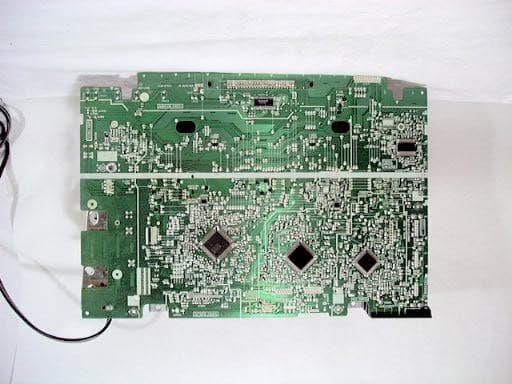
Click to zoom
Application Details
- Equipment Class
- HID - Part 15 TV Interface Device
- Date of Grant
- Mar 07, 2000
- Application Purpose
- Original Equipment
- Date of Application
- Mar 01, 2000
- Equipment Note
- VCR
- Frequency Range
- 67.25000000 - 71.75000000
- Country
- United States
Documents & Files
Document Text
Text extracted from the exhibit documents filed with the FCC. Open a document above to read the original.
Users Manual
2 Important Safeguards and Precautions This symbol warns the user that uninsulated voltage within the unit may have sufficient magnitude to cause electric shock. Therefore, it is dangerous to make any kind of contact with any inside part of this unit. This symbol alerts the user that important literature concerning the operation and maintenance of this unit has been included. Therefore, it should be read carefully in order to avoid any problems. Safety Precautions Warning: To prevent fire or shock hazard, do not expose this equipment to rain or moisture. CAUTION: TO REDUCE THE RISK OF ELECTRIC SHOCK, DO NOT REMOVE COVER (OR BACK) RISK OF ELECTRIC SHOCK DO NOT OPEN CAUTION NO USER-SERVICEABLE PARTS INSIDE REFER SERVICING TO QUALIFIED SERVICE PERSONNEL FOR YOUR SAFETY, READ AND RETAIN ALL SAFETY AND OPERATING INSTRUCTIONS. HEED ALL WARNINGS IN THE MANUAL AND ON THE UNIT USING THE VIDEO UNIT If the unit has been in storage or moved to a new location, refer first to the INSTALLATION section of these safeguards. 1 KEEP THIS VIDEO UNIT AWAY FROM WATER OR MOISTURE OF ANY KIND. 2 IF EQUIPMENT IS EXPOSED TO RAIN, MOISTURE, OR STRONG IMPACT, unplug the unit and have it inspected by a qualified service technician before use. 3 DURING AN ELECTRICAL STORM During a lightning storm, whether indoors or outdoors, or before leaving the unit unused for extended periods of time, disconnect all equipment from the power source as well as the antenna and cable system. 4 WHEN THE UNIT IS PLUGGED IN • Never expose the unit to rain or water. DO NOT OPERATE if liquid has been spilled into the unit. Immediately unplug the unit, and have it inspected by a service technician. Fire and shock hazards can result from electrical shorts caused by liquid contact inside. •Never drop or push any object through openings in the unit. Some internal parts carry hazardous voltages and contact can cause electric shock or fire hazard. • Avoid placing the unit directly above or below your TV set as this may cause electrical interference. Keep all magnets away from electronic equipment. 5 USING ACCESSORIES Use only accessories recommended by the manufacturer to avoid risk of fire, shock, or other hazards. 6 CLEANING THE UNIT Unplug the unit. Then, use a clean, dry, chemically untreated cloth to gently remove dust or debris. DO NOT USE cleaning fluids, aerosols, or forced air that could over-spray, or seep into the unit and cause electrical shock. Any substance such as wax, adhesive tape, etc. may mar the cabinet surface. Exposure to greasy, humid, or dusty areas may adversely affect internal parts. INSTALLATION 1 POWER SOURCE CAUTION Operate only from a power source indicated on the unit or in this manual. If necessary, have your Electric Utility Service Company or Video Products Dealer verify the power source in your home. 2 POLARIZED OR GROUNDING PLUG As a safety feature, this Video product comes with either a polarized power cord plug (one blade is wider than the other), or a three-wire grounding type plug. POLARIZED PLUG CAUTION: This plug will only fit into an outlet one way. If you cannot fully insert the plug, try reversing it. If it still will not fit, have an electrician install the proper wall outlet. Do not defeat the safety feature by tampering with the plug. GROUNDING PLUG CAUTION: This plug will only fit into a three-hole grounding outlet. If necessary, have an electrician install the proper outlet. Do not defeat the safety feature by tampering with the plug. 3 POWER CORD Make sure power cords are routed so that they are not likely to have anything rest on them, roll over them, or be in the way of walking traffic. If an extension cord is used, make sure it also has either a polarized or grounded plug and that the cords can be securely connected. Frayed cords, damaged plugs, and damaged or cracked wire insulation are hazardous and should be replaced by a qualified service technician. Overloaded outlets and extension cords are fire hazards and should be avoided. 4 DO NOT BLOCK VENTILATION HOLES Ventilation openings in the cabinet release heat generated during operation. If they are blocked, heat build-up inside the unit can cause failures that may result in a fire hazard or heat damage to cassettes. For protection, follow these rules: a. Never cover ventilation slots or the unit while in use, or operate the unit when placed on a bed, sofa, rug, or other soft surface. b. Avoid built-in installation, such as a book case or rack, unless proper ventilation is provided. 5 AVOID EXTREMELY HOT LOCATIONS OR SUDDEN TEMPERATURE CHANGES Do not place the unit over or near any kind of heater or regulator, in direct sunlight, inside a closed vehicle, etc.. Do not move the unit suddenly between areas of extreme temperature variation. If the unit is suddenly moved from a cold place to a warm place, moisture may condense in the unit and on the tape. 6 TO AVOID PERSONAL INJURY • Do not place unsecured equipment on a sloping surface. • Do not place this unit on any support that is not firm, level, and adequately strong. The unit could fall causing serious injury to a child or adult and damage to the unit. • An appliance and cart combination should be moved with care. Quick stops, excessive force, and uneven surfaces may cause the appliance and cart combination to overturn. • Carefully follow all operating instructions and use the manufacturer's recommended accessories when operating this unit or connecting it to any other equipment. SERVICE 1 DO NOT SERVICE THIS PRODUCT YOURSELF If, after carefully following the detailed operating instructions, this Video product does not operate properly, do not attempt to open or remove covers, or make any adjustments not described in the manual. Unplug the unit and contact a qualified service technician. 2 IF REPLACEMENT PARTS ARE REQUIRED Make sure the service technician uses only parts specified by the manufacturer, or those having the same safety characteristics as the original parts. The use of unaut…
Text truncated - open the document above for the full version.
Block Diagram
EXHIBIT #: 5 FCC ID: ACJ927128AHP OUR REF.: MKES00-F002 MODEL NO.: NV-FJ4620PX Block Diagram
Cover Letter(s)
Description of Application Model FCC ID: ACJ927128AHP OUR REF.: MKES00-F002 MODEL NO.: NV-FJ4620PX Application model is as below. FCC ID: ACJ927128AHP Appliance name: Video Cassette Recorder Grantee Name: Matsushita Electric Industrial Co., Ltd. Model No.: NV-FJ4620PX Brand Name: Panasonic Chassis No.: KG-20WHGPX Cabinet Material: Top, Side: Steel Bottom: Steel & Plastics Rear, Front: Plastics RF Converter: VEQS0614 (RF Converter circuit is included in RF Demodulator) Output Channel: CH 3 & 4 Broadcast Channels VHF 2-13, UHF 14-69 CATV Channels: Mid band A through I (14-22) Super band J through W (23-36) Hyper band AA - EEE (37-64) Low band A-5 - A-1 (95-99) Special CATV channel 5A (01) Ultra band 65-94, 100-125 Antenna Terminal: One VHF/UHF Input Antenna Terminal and One VHF/UHF Output Terminal are provided. Impedance: 75 ohms Transfer SW is provided in RF Demodulator circuit. Power splitter is provided in RF Demodulator circuit. Highest frequency- generated or used: 847 MHz (Local oscillator frequency of UHF Ch69) 71.75 MHz (Aural carrier frequency of Converter Ch4) Input Terminal: Video and Audio Input Terminals are provided. Remote Controller: Wireless
Cover Letter(s)
EXHIBIT #: 4-2 FCC ID: ACJ927128AHP OUR REF.: MKES00-F002 MODEL NO.: NV-FJ4620PX Description of RF Converter CircuitPage 1/2 1) Type(s) of emission Not applicable 2) Frequency range USA standard broadcasting signal CHANNEL 3 & 4 3) Range of operating power and description of means provided for Variation of operating power Not applicable 4) Maximum power rating as defined in the applicable rules Not applicable 5) Tune up procedure over the power range or at specific operating power levels Not applicable 6) A description of all circuitry and devices provided for determining and stabilizing frequency Video Carrier Frequency Frequency of video carrier output is determined by output of PLL1(4MHz).Consequently, the frequency stability is determined by PLL1 (4MHz) which is nominally 0.2 %. Audio Carrier Frequency Audio Carrier Frequency is generated by mixing of video carrier and output signal of the FM-OSC circuit in the RF-MIXER circuit of IC201. The output signal of the FM-OSC circuit is generated by modulating of audio input signal and output signal of PLL2(4.5MHz). Frequency of audio carrier output is determined by output of PLL2. The frequency stability is determined by PLL2 and maintained within 0.2%. 7) A description of any circuits or devices employed for suppression of spurious radiation, for limiting modulation, and for limiting the operating power. a. Limit of Modulation Modulations for video carrier and audio carrier are limited, because both inputs supplied from VCR are maintained constant. b. Limit of Operating Power Not applicable EXHIBIT #: 4-2 FCC ID: ACJ927128AHP OUR REF.: MKES00-F002 MODEL NO.: NV-FJ4620PX Description of RF Converter CircuitPage 2/2 8) Function of each electron tube, semiconductor or other active circuit device RF oscillator (IC201) The video carrier frequency is generated by RF oscillator circuit and controlled by PLL1 circuit. Generated video carrier frequency is supplied to RF MIXER circuit through the Buffer Amplifier. RF MIXER (IC201) The output of RF oscillator and video signal from white clip circuit are supplied to RF MIXER. Amplitude modulated video carrier is obtained as RF output through the buffer amplifier. FM modulated audio signal is supplied to RF MIXER from FM oscillator. The output of RF oscillator is made both side-band modulation by FM modulated audio signal, as result, audio carrier is obtained as RF output through the buffer amplifier. Clamp and White Clip (IC201) The video input is clamped by Sync-Chip. It prevents from over-modulation. RF MIXER (IC201) The oscillated frequency is adjusted to 4.5MHz by PLL2. Audio signal is supplied to the FM oscillator FM modulated audio carrier is obtained as an output. REF oscillator (IC201) Each reference frequency that generated in REF oscillator circuit is supplied to PLL1 and PLL2 for control of RF oscillator and FM oscillator. Carrier OFF SW When TV side selected by TV/VCR SW, carrier OFF SW circuit shut off power of the RF oscillator circuit and RF MIXER circuit. RF Converter Block Diagram
Cover Letter(s)
EXHIBIT #: 4-1 FCC ID: ACJ927128AHP OUR REF.: MKES00-F002 Technical SpecificationMODEL NO.: NV-FJ4620PX Power Source:AC 110 / 120 / 220 / 240 V 50 / 60 Hz Power Consumption :Approx. 23W Television System :EIA Standard (525 lines, 60 fields) NTSC Luminance : Frequency modulation Color Signal : converted sub carrier direct recording Audio Track :1 track (Normal) 2 Channels (Hi-Fi Sound) Tape Format :Tape width 1/2" (12.7 mm), high density tape Tape Speed :33.35 mm/sec. at SP mode 16.67 mm/sec. at LP mode 11.12 mm/sec. at SLP mode Record/Playback Time :480 min. (max.) FF/REW Time :Less than 5 min.(T-120) Heads :Video : 4 rotary heads Audio : 1 stationary head (Normal) 2 rotary heads (Hi-Fi Sound) Control : 1 stationary head Erase : 1 full track Input Level :Video : Video Input Connector 1.0 V p-p, 75 ohms Audio : Audio Input Connector -10 dBV, 47k ohms Output Level :Video : Video Output Connector 1.0 V p-p, 75 ohms Audio : Audio Output Connector -8 dBV, 600 ohms RF Modulated Output :Channel 3 and 4 (selective) RF Input :Same as conventional TV receiver Video Horizontal Resolution:Color & B/W : More than 230 lines (VHS mode) (on mono scope test pattern) Audio Frequency Response :100 Hz - 8 kHz at SP mode (Normal Audio Sound) 20 Hz-20 kHz (Hi-Fi Audio Sound) Signal to Noise Ratio :Video : More than 43 dB at SP mode (VHS) Audio : More than 42 dB at SP mode (Normal) More than 60 dB (Hi-Fi) Operating Humidity :10 % - 75 % Operating Temperature :41F - 104F (5 - 40)
External Photos
EXHIBIT #: FCC ID: ACJ927128AHP OUR REF.: MKES00-F002 MODEL NO.: NV-FJ4620PX Sheet 1 of 6 Sheets EXHIBIT #: FCC ID: ACJ927128AHP OUR REF.: MKES00-F002 MODEL NO.: NV-FJ4620PX Sheet 2 of 6 Sheets Main PCB (Top view) Main PCB (Top view) Tuner (RF Converter) AC Cord Video in 2 Audio in 2 Tuner (RF Converter) Video in 1 Audio in 1 EXHIBIT #: FCC ID: ACJ927128AHP OUR REF.: MKES00-F002 MODEL NO.: NV-FJ4620PX Sheet 3 of 6 Sheets Main PCB (Bottom view) EXHIBIT #: FCC ID: ACJ927128AHP OUR REF.: MKES00-F002 MODEL NO.: NV-FJ4620PX Sheet 4 of 6 Sheets Power PCB (Top view) Power PCB (Bottom view) EXHIBIT #: FCC ID: ACJ927128AHP OUR REF.: MKES00-F002 MODEL NO.: NV-FJ4620PX Sheet 5 of 6 Sheets Tuner (VEQS0614: Top view) Tuner (VEQS0614: Top view) In from antenna Out to TV RF Converter EXHIBIT #: FCC ID: ACJ927128AHP OUR REF.: MKES00-F002 MODEL NO.: NV-FJ4620PX Sheet 6 of 6 Sheets Tuner (VEQS0614: Bottom View) Tuner (VEQS0614: Bottom View) Audio inVideo inCH. SWTV/VCR SW5V RF Converter IC201 RF Converter
ID Label/Location Info
EXHIBIT #: 1 FCC ID: ACJ927128AHP OUR REF.: MKES00-F002 MODEL NO.: NV-FJ4620PX Sample of FCC Identifier Sample of Statement for compliance with FCC Rules Part 15 EXHIBIT #: 2 FCC ID: ACJ927128AHP OUR REF.: MKES00-F002 MODEL NO.: NV-FJ4620PX Location of FCC Identifier 1. Enclosure Rear Nameplate with FCC Identifier 2. Enclosure Bottom Statement for Compliance with FCC Rules Part 15
Test Report
EXHIBIT #: 3 FCC ID: ACJ927128AHP OUR REF.: MKES00-F002 MODEL NO.: NV-FJ4620PX Part 15 Subpart B, (TV Interface Device)Sheet 3 of 17 Sheets 1) 15.107 Power Line Conducted Voltage Meter Read. (dBuV)Interference (dBuV) Video Signal Freq. (MHz) 1-end & Gro. The other- End&Gro. LISN Factor (dB) Matching Pad Loss (dB) 1-end & Gro. The other- End &Gro. 0.45 27.726.5 0.16.234.032.8 0.62 25.226.6 0.16.231.532.9 0.85 26.126.2 0.16.232.432.5 1.09 23.524.0 0.16.229.830.3 4.15 18.518.4 0.36.225.024.9 Multi Burst 1 V p-p 28.64 23.822.8 1.06.231.030.0 0.45 28.327.3 0.16.234.633.6 0.62 26.227.2 0.16.232.533.5 0.85 27.926.3 0.16.234.232.6 1.09 24.524.2 0.16.230.830.5 4.15 22.320.2 0.36.228.826.7 Multi Burst 5 V p-p 28.64 24.322.8 1.06.231.530.0 0.45 27.226.5 0.16.233.532.8 0.62 24.926.3 0.16.231.232.6 0.85 23.723.8 0.16.230.030.1 1.09 22.222.3 0.16.228.528.6 4.15 18.017.7 0.36.224.524.2 Internal Signal 28.64 23.323.0 1.06.230.530.2 0.45 27.526.0 0.16.233.832.3 0.62 25.225.9 0.16.231.532.2 0.85 23.323.0 0.16.229.629.3 1.09 18.418.6 0.16.224.724.9 4.15 19.018.7 0.36.225.525.2 RF/CATV Signal Input 28.64 23.422.8 1.06.230.630.0 Note: 1. Sample calculation at M.B., 1 V p-p, 1-end & Gro. 0.45 MHz ; 27.7 + 0.1 + 6.2 = 34.0 (dBuV) 2. Measuring Instruments: a) Field strength meter - Kyoritsu Electric Work Co., Ltd. Model : KNM-402C (1) Detector function: CISPR Q-Peak (2) IF band width : 9 kHz (3) Input impedance : 75 ohms b) Line impedance stabilized network (LISN) - Kyoritsu Electric Work CO., Ltd. Model : KNW-406 50 ohms / 50 uH network c) Test Signal Generator- Shibasoku Co., Ltd. (Multi Burst) Model : 205 d) Matching pad - Kyoritsu Electric Work Co., Ltd. Model : KPD-401 3. The spectrum was checked from 0.45 MHz to 30 MHz and the six highest emissions relative to the appropriate limit were measured and reported. EXHIBIT #: 3 FCC ID: ACJ927128AHP OUR REF.: MKES00-F002 MODEL NO.: NV-FJ4620PX Part 15 Subpart B, (TV Interface Device)Sheet 4 of 17 Sheets 2) 15.109 Radiated Emission(Including Tuner, Without Accessories) Meter Reading Open Volt. (dBuV) Emission & 3 meters(dBuV) Video Signal Frequency (MHz) Horiz.Vert. Correction Factor (dB) Open Vol. Horiz.Vert. 71.27 10.211.5 7.8 18.019.3 143.18 9.710.4 17.2 26.927.6 150.34 8.48.0 17.7 26.125.7 171.82 15.38.2 18.6 33.926.8 898.00 7.05.1 31.2 38.236.3 Multi Burst 1 V p-p 1510.00 5.47.6 35.2 40.642.8 71.27 10.613.0 7.8 18.420.8 143.18 10.610.4 17.2 27.827.6 150.34 8.98.2 17.7 26.625.9 171.82 15.28.3 18.6 33.826.9 898.00 7.05.1 31.2 38.236.3 Multi Burst 5 V p-p 1510.00 5.47.6 35.2 40.642.8 71.27 9.611.3 7.8 17.419.1 143.18 9.09.1 17.2 26.226.3 150.34 5.35.1 17.7 23.022.8 171.82 13.27.4 18.6 31.826.0 898.00 7.05.1 31.2 38.236.3 Internal Signal 1510.00 5.47.6 35.2 40.642.8 71.27 9.911.5 7.8 17.719.3 143.18 9.09.4 17.2 26.226.6 150.34 5.36.1 17.7 23.023.8 171.82 13.27.3 18.6 31.825.9 898.00 7.05.1 31.2 38.236.3 RF/CATV Signal Input 1510.00 5.47.6 35.2 40.642.8 Note:1. Sample calculation at M.B., 1 V p-p, Horiz. 71.27 MHz ; 10.2 + 7.8 = 18.0 (dBuV/m) 2. Measuring Instruments: a) Field strength meter - Hewlett Packard company Model: HP 8546A (1) Frequency range: 9 kHz to 6.5 GHz (2) RF Input: 50 ohm (3) IF band width: 200 Hz/ 9 kHz/ 120 kHz/ 1MHz (4) Detector function: Average/CISPR Q-Peak/Peak b) Test Signal Generator - Shibasoku Co., Ltd. (Multi Burst)Model: TG-5, 2U2 c) Receiving antenna- Schwarzbeck Model: VHA9103 30 - 300 MHz Model: UHALP9107 300 - 1000 MHz - The Electro-Mechanics Company Model: 3115 1 - 18G Hz 3. The spectrum was checked from 30 MHz to 1694 MHz and the six highest emissions relative to the appropriate limit were measured and reported. EXHIBIT #: 3 FCC ID: ACJ927128AHP OUR REF.: MKES00-F002 MODEL NO.: NV-FJ4620PX Part 15 Subpart B, (TV Interface Device)Sheet 5 of 17 Sheets 2) 15.109 Radiated Emission(Including Tuner, With Accessories) Meter Reading Open Volt. (dBuV) Emission & 3 meters(dBuV) Video Signal Frequency (MHz) Horiz.Vert. Correction Factor (dB) Open Vol. Horiz.Vert. 71.27 18.119.5 7.8 25.927.3 143.18 13.913.2 17.2 31.130.4 150.34 12.711.1 17.7 30.428.8 171.82 15.88.2 18.6 34.426.8 898.00 10.39.4 31.2 41.540.6 Multi Burst 1 V p-p 1510.00 6.69.6 35.2 41.844.8 71.27 17.019.7 7.8 24.827.5 143.18 13.213.0 17.2 30.430.2 150.34 12.110.9 17.7 29.828.6 171.82 16.09.2 18.6 34.627.8 898.00 10.39.4 31.2 41.540.6 Multi Burst 5 V p-p 1510.00 6.69.6 35.2 41.844.8 71.27 17.419.0 7.8 25.226.8 143.18 12.712.6 17.2 29.929.8 150.34 13.110.4 17.7 30.828.1 171.82 16.08.4 18.6 34.627.0 898.00 10.39.4 31.2 41.540.6 Internal Signal 1510.00 6.69.6 35.2 41.844.8 71.27 17.319.6 7.8 25.127.4 143.18 13.012.1 17.2 30.229.3 150.34 13.710.5 17.7 31.428.2 171.82 16.48.5 18.6 35.027.1 898.00 10.39.4 31.2 41.540.6 RF/CATV Signal Input 1510.00 6.69.6 35.2 41.844.8 Note:1. Sample calculation at M.B., 1 V p-p, Horiz. 71.27 MHz ; 18.1 + 7.8 = 25.9 (dBuV/m) 2. Measuring Instruments: a) Field strength meter - Hewlett Packard company Model: HP 8546A (1) Frequency range: 9 kHz to 6.5 GHz (2) RF Input: 50 ohm (3) IF band width: 200 Hz/ 9 kHz/ 120 kHz/ 1MHz (4) Detector function: Average/CISPR Q-Peak/Peak b) Test Signal Generator - Shibasoku Co., Ltd. (Multi Burst)Model: TG-5, 2U2 c) Receiving antenna- Schwarzbeck Model: VHA9103 30 - 300 MHz Model: UHALP9107 300 - 1000 MHz - The Electro-Mechanics Company Model: 3115 1 - 18G Hz 3. The spectrum was checked from 30 MHz to 1694 MHz and the six highest emissions relative to the appropriate limit were measured and reported. EXHIBIT #: 3 FCC ID: ACJ927128AHP OUR REF.: MKES00-F002 MODEL NO.: NV-FJ4620PX Part 15 Subpart B, (TV Interface Device)Sheet 6 of 17 Sheets 3) 15.111 (a) Antenna Power Conducted Voltage Frequency (MHz) Meter Reading (dBuV) Matc. Pad Loss (dB) Interference (dBuV) 413.033.48.842.2 419.033.58.842.3 1162.036.68.845.4 1166.0 37.4 8.846.2 1174.038.48.847.2 1178.037.38.846.1 Antenna Input Impedance: 75 ohms (Unbalanced) Note: 1. Sample calculation at 413.0 MHz ; 33.4 + 8.8 = 42.2 (dBuV) 2. Measuring Instrument: a) Spectrum Analy…
Text truncated - open the document above for the full version.
Contact Information
Applicant
Ben Botros(Project Manager)
Technical Contact
Matsushita Electric Corp of AmericaRichard Mullen
[email protected](201) 348-7758
One Panasonic Way, 4B-8 · Secaucus, New Jersey · United States
Test Firm
Panasonic Healthcare Co., LtdOsamu Kobashi
[email protected]81-897-56-1111
Technical Specifications
| # | Rule Parts | Frequency Range | Power Output | Tolerance |
|---|---|---|---|---|
| 2 | 15B | 67.25 MHz - 71.75 MHz | - | % |
Other Applications from Panasonic Corporation of North America
ACJ-EAH-A1000
Aug 19, 2026Digital Wireless Stereo Headphones
Equipment Class
DSS - Part 15 Spread Spectrum TransmitterACJ9TGFZVNF3G1
Jun 16, 2026Contactless Smart Card Reader
Equipment Class
DXX - Part 15 Low Power Communication Device Transmitter
ACJ932AM2301
Jan 29, 2025Car AV Control Unit for CDC
Equipment Class
DTS - Digital Transmission SystemACJ96NKX-TGEA60B
Aug 13, 2024DECT Handset
Equipment Class
PUE - Part 15 Unlicensed PCS portable Tx held to earACJ96NKX-TGE630B
Aug 12, 2024DECT Base Unit
Equipment Class
PUB - Part 15 Unlicensed PCS Base Station