ACJ927130TXFM Transmitter used With TV/VCR
Panasonic Corporation of North America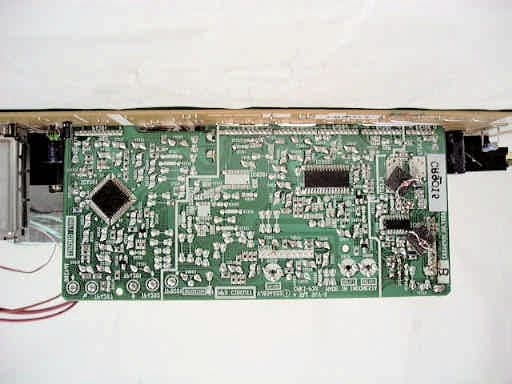
Click to zoom
Application Details
- Equipment Class
- DXX - Part 15 Low Power Communication Device Transmitter
- Date of Grant
- Feb 08, 2000
- Application Purpose
- Original Equipment
- Date of Application
- Nov 17, 1999
- Equipment Note
- FM Transmitter used With TV/VCR
- Frequency Range
- 88.10000000 - 107.90000000
- Country
- United States
Documents & Files
Document Text
Text extracted from the exhibit documents filed with the FCC. Open a document above to read the original.
Users Manual
Important Safeguards and Precautions GROUND CLAMP ELECTRIC SERVICE EQUIPMENT ANTENNA LEAD IN WIRE ANTENNA DISCHARGE UNIT (NEC SECTION 810-20) GROUNDING CONDUCTORS (NEC SECTION 810-21) GROUND CLAMPS POWER SERVICE GROUNDING ELECTRODE SYSTEM (NEC ART 250, PART H) NEC- NATIONAL ELECTRICAL CODE 2 INSTALLATION 1 POWER SOURCE CAUTION Operate only from power source indicated on unit or in this manual. If uncertain, have your Electric Utility Service Company or Video Products Dealer verify your home power source. 2 POWER CORD PLUG For safety, this unit has a polarized type plug (one wide blade), or a three-wire grounding type plug. Always hold the plug firmly and make sure your hands are dry when plugging in or unplugging the AC power cord. Regularly remove dust, dirt, etc. on the plug. POLARIZED PLUG CAUTION: The plug fits into outlet one way. If it cannot be fully inserted, try reversing it. If it still will not fit, have an electrician install the proper wall outlet. Do not tamper with the plug. GROUNDING PLUG CAUTION: The plug requires a three-hole grounding outlet. If necessary, have an electrician install the proper outlet. Do not tamper with the plug. 3 POWER CORD To avoid unit malfunction, and to protect against electrical shock, fire or personal injury: - Keep power cord away from heating appliances and walking traffic. Do not rest heavy objects on, or roll such objects over the power cord. - Do not tamper with the cord in any way. - An extension cord should have the same type plug (polarized or grounding) and must be securely connected. - Overloaded wall outlets or extension cords is a fire hazard. - Frayed cords, damaged plugs, and damaged or cracked wire insulation are hazardous and should be replaced by a qualified electrician. 4 DO NOT BLOCK VENTILATION HOLES Ventilation openings in the cabinet release heat generated during operation. If blocked, heat build-up may result in a fire hazard or heat damage to cassettes. For your protection: a. Never cover ventilation slots while unit is ON, or operate unit while placed on a bed, sofa, rug, or other soft surface. b. Avoid built-in installation, such as a book case or rack, unless properly ventilated. 5 AVOID EXTREMELY HOT LOCATIONS OR SUDDEN TEMPERATURE CHANGES Do not place unit over or near a heater or regulator, in direct sunlight, etc. If unit is suddenly moved from a cold place to a warm place, moisture may condense in unit and on the tape causing damage. 6 TO AVOID PERSONAL INJURY • Never place unit on support or stand that is not firm, level, and adequately strong. The unit could fall causing serious injury to a child or adult and damage to the unit. • Move any appliance and cart combination with care. Quick stops, excessive force, and uneven surfaces may cause objects to overturn. • Carefully follow all operating instructions. OUTDOOR ANTENNA INSTALLATION 1 SAFE ANTENNA AND CABLE CONNECTION An outside antenna or cable system must be properly grounded to provide some protection against built up static charges and voltage. Section 810 of the National Electrical Code, ANSI/NFPA 70 (in Canada, part 1 of the Canadian Electrical Code) provides information regarding proper grounding of the mast and supporting structure, grounding of the lead-in wire to an antenna discharge unit, size of grounding conductors, location of antenna discharge unit, connection to grounding electrodes, and requirements for the grounding electrode. 2 KEEP ANTENNA CLEAR OF HIGH VOLTAGE POWER LINES OR CIRCUITS Locate an outside antenna system well away from power lines and electric light or power circuits so it will never touch these power sources should it ever fall. When installing antenna, absolutely never touch power lines, circuits or other power sources as this could be fatal. USING THE UNIT Before unit is brought out of storage or moved to a new location, refer again to the INSTALLATION section of these safeguards. 1 KEEP UNIT WELL AWAY FROM WATER OR MOISTURE, such as vases, sinks, tubs, etc. 2 IF EXPOSED TO RAIN, MOISTURE, OR STRONG IMPACT, unplug unit and have it inspected by a qualified service technician before use. 3 ELECTRICAL STORMS During a lightning storm, or before leaving unit unused for extended periods of time, disconnect all equipment from the power source as well as the antenna and cable system. 4 WHEN UNIT IS PLUGGED IN • DO NOT OPERATE IF: - liquid has spilled into unit. - unit was dropped or otherwise damaged. - unit emits smoke, malodors, or noises. Immediately unplug unit, and have it inspected by a service technician to avoid potential fire and shock hazards. • Never drop or push any object through openings in unit. Touching internal parts may cause electric shock or fire hazard. • Keep magnetic objects, such as speakers, away from unit to avoid electrical interference. 5 USING ACCESSORIES Use only accessories recommended by the manufacturer to avoid risk of fire, shock, or other hazards. 6 CLEANING UNIT Unplug unit. Use a clean, dry, chemically untreated cloth to gently remove dust or debris. DO NOT USE cleaning fluids, aerosols, or forced air that could over-spray, or seep into unit and cause electrical shock. Any substance, such as wax, adhesive tape, etc. may mar the cabinet surface. Exposure to greasy, humid, or dusty areas may adversely affect internal parts. SERVICE 1 DO NOT SERVICE PRODUCT YOURSELF If, after carefully following detailed operating instructions, the unit does not operate properly, do not attempt to open or remove covers, or make any adjustments not described in the manual. Unplug unit and contact a qualified service technician. 2 REPLACEMENT OF PARTS Make sure the service technician uses only parts specified by the manufacturer, or have equal safety characteristics as original parts. The use of unauthorized substitutes may result in fire, electric shock, or other hazards. 3 SAFETY CHECK AFTER SERVICING After unit is serviced or repaired, request that a through safety check be done as described in the manufacturer’…
Text truncated - open the document above for the full version.
Users Manual
32 For assistance, call 1-800-211-PANA(7262) VIDEO INVIDEO INAUDIO INAUDIO IN POWERPOWERVOLVOLCHCHSTOP/EJECTSTOP/EJECTREW/REW/ PLAY/REPEATPLAY/REPEAT FF/FF/RECRECTIMER/FMTIMER/FM ACTIONACTION RECRECON TIMERON TIMER PROG TIMERPROG TIMER Weak Signal Display ON/OFF 1 Display MAIN MENU. Press ACTION*. Display SET UP CH screen. 1) Press to select “CH.” 2) Press ACTION to display. Select WEAK SIGNAL DISPLAY. 1) Press to select. 2) Press to set “ON” or “OFF.” Return to the normal screen. Press ACTION twice. 2 When “ON” is selected, picture is displayed even when broadcast signal is weak or nonexistent. 4 3 • “ON” = Picture is displayed regardless of signal condition, and may not always be clearly visible. “OFF” = Screen turns solid blue when signal is absent or weak. • If unit is connected to equipment which has blue back feature, selecting “ON” will have no effect on the other equipment. VCR Lock All operations are prohibited except Timer recording and tape eject. Useful for families with small children. To turn “ON.” In stop mode, hold down REC on the unit without a cassette inserted for 7 seconds. To turn “OFF.” Repeat above with or without cassette. • VCR Lock is canceled automatically after about 24 hours if clock is set. REC Special VCR Features (continued) Notes C H + V O L V O L C H C H + V O L V O L C H ANTENNA : CABLE A UTO SET CHANNEL CAPT I ON WEAK S I GNAL GNAL D I SPLAYSPLAY : OFFOFF CABLE BOX SET UP V CR P l u s+ CH SET UP SELE CT : KEY SET : KEY END : ACT I ON KEY SET UP CHANNEL C H + V O L V O L C H V C R + ACTION 2 • 3 SET SELECT :CH UP :CH DOWN :VOL UP : VOL DOWN 1 • 2 • 4 Model PV-C2060 unit is shown here. REC REC VCR LOCK ACT I VATED VCR LOCK OFF M A I N MENU CLOCKC H SET : ACT I ON KEY SELECT : KEY VCR T V EX I T LANGUAGE 99.12.14, 11:33 PM32 33 Advanced Operation Copy Your Tapes (Dubbing) Connections you’ll need to make. Playback (Source) VCR 1 Recording (Editing) unit Insert pre- recorded tape. Put in Standby mode. Press PLAY then PAUSE at starting point. Start dubbing. Press PLAY. Stop dubbing. Press STOP/ EJECT. Insert blank tape with record tab. • Dubbing tapes protected with Copy Guard will have poor quality results. Put in Standby mode. Press REC, then PAUSE/SLOW immediately. Start dubbing. Press PAUSE/SLOW. Stop dubbing. Press STOP. Our Vacation 2 Select “LINE” mode. See “Selecting Input Mode” section on page 13. 3 4 5 EJECT STOP PAUSE PLAY •Unauthorized exchanging and/or copying of copyrighted recordings may be copyright infringement. OUT IN IN FROM ANT. OUT TO TV AUDIO IN AUDIO VIDEO IN Playing (Source) VCR OUT IN IN FROM ANT. OUT TO TV L-AUDIO IN-R VIDEO R-AUDIO-L VIDEO IN Playing (Source) VCR MONO <Model PV-C2060 unit is shown here.> Caution <Model PV-C2080 unit is shown here.> VIDEO Recording (Editing) unit if the remote control POWER, CH Up/Down, NUMBERED keys, ACTION, PROG/VCR+, DISPLAY, SEARCH, R-TUNE, FM/TV, or ADD/DLT button does not work when pressed, press COMBO button on the remote and try the button again. * Important: Recording (Editing) unit PLAY 99.12.14, 11:33 PM33 34 For assistance, call 1-800-211-PANA(7262) VIDEO IN VIDEO IN AUDIO IN AUDIO IN POWER POWER VOL VOL CH CH STOP/EJECT STOP/EJECT REW/ REW/ PLAY/REPEAT PLAY/REPEAT FF/ FF/ REC REC TIMER/FM TIMER/FM ACTION ACTION REC REC ON TIMER ON TIMER PROG TIMER PROG TIMER FM Radio 2 FM Radio is ... This unit has an FM radio with built-in antenna, 9 station preset, and a band range of 87.5 ~ 108.1 MHz. You can even set the On-Timer (page 20) to wake up to your favorite radio station. Display FM radio mode. Press FM/TV* on the remote or TIMER/FM twice on the unit. Select the FM number. 1 Continued on the next page... TIMER/FM Press a NUMBERED key (1~9.) To Make Corrections, select station with a NUMBERED key, then do step 3 again. To exit FM mode, press FM/TV on the remote or TIMER/FM twice on the unit. Set the radio station. 1) Press CH to select the desired radio station. (Each press changes frequency 200 kHz.) 2) Press ADD/DLT to set. Quick Station Scan Hold down CH or for a few seconds, then release to scan for FM stations in your area. • To cancel, press CH or while in search mode. 3 C H C H FM ANTENNA Setup a Display MAIN MENU. Press ACTION. Display SET UP TV screen. 1) Press to select “TV.” 2) Press ACTION to display. b C H + VOL VOL C H Make sure FM tuning is done correctly (See FM Radio Setup.) 1 Model PV-C2060 unit is shown here. FM Radio Setup FM 1 87. 5MHz 1 2 : 0 0PM FM 1 8 7. 7MHz MEMORY : PUSH ADD / DLT KEY 1 2 : 0 0PM FM 1 8 7. 7MHz MEMOR I ZED 1 2 : 0 0PM M A I N MENU T V VCR EX I T CLOCKC H LANGUAGE SET : ACT I ON KEY SELECT : KEY 99.12.14, 11:32 PM34 35 Advanced Operation LOCK CA PT I ON INPUT SELCT : TUNER V I DEO ADJUST F M ANTENNA ANTENNA : I NTNT SELECT : KEY SET : KEY END : ACT I ON KEY SET UP TV VIDEO IN VIDEO IN AUDIO IN AUDIO IN POWER POWER VOL VOL CH CH STOP/EJECT STOP/EJECT REW/ REW/ PLAY/REPEAT PLAY/REPEAT FF/ FF/ REC REC TIMER/FM TIMER/FM ACTION ACTION REC REC ON TIMER ON TIMER PROG TIMER PROG TIMER TIMER/FM B Display FM radio mode. Press FM/TV on the remote or TIMER/FM twice on the unit. A To cancel, press FM/TV on the remote or TIMER/FM twice on the unit. •FM radio cannot be recorded on a Video cassette. •You may get better reception by repositioning the unit. •You cannot select FM Radio mode during playback or record, or while a blue back (PROG, ACTION, MENU) screen is displayed. To select Audio Mode for FM Radio Select “STEREO” or “MONO.” Press AUDIO repeatedly in FM Radio mode. Notes c d C H + VOL VOL C H Select FM ANTENNA. 1) Press to select. 2) Press to select “INT (INTERNAL)” or “EXT (EXTERNAL)” whichever sounds the best. End setup. Press ACTION twice to exit. Select the FM number. Press a NUMBERED key (1~9) to select a preset station (see steps 2 and 3 on the previous page.) A C H + VO L VO L C H FM/TV NUMBERED Keys AUDIO A B V C R + DISPLAY Model PV-C2060 unit is shown here. Once stations are set, the selected station and current time are displayed when FM Radio…
Text truncated - open the document above for the full version.
Cover Letter(s)
Description of Application Model FCC ID:ACJ927130TX OUR REF:MKES99-F023 MODEL NO.PV-C2080 Application model is as below. (This model is TV/VCR combination with FM Transmitter.) FCC ID:ACJ927130TX Appliance name:Intentional Radiators : FM Transmitter Grantee Name:Matsushita Electric Industrial Co., Ltd. Model No.:PV-C2080 Brand Name:Panasonic Chassis No.:KM-2000 Cabinet Material:Plastics Remote Controller:Wireless FM Transmitter portion: FM Transmitter:VEPS4033 Output Frequency:88.1MHz – 107.9 MHz Output Antenna:Foil-pattern on the main PCB TV/VCR combination portion: Broadcast ChannelsFM 87.5 MHz – 108.1 MHz, VHF 2-13, UHF 14-69 CATV Channels:Mid band A through I (14-22) Super band J through W (23-36) Hyper band AA - EEE (37-64) Low band A-5 - A-1 (95-99) Special CATV channel 5A (01) Ultra band 65-94, 100-125 Antenna Terminal:One FM/VHF/UHF Input Antenna Terminal Impedance:75 ohms Highest frequency- generated or used:847 MHz (Local oscillator frequency of UHF Ch69) Input Terminal:Video and Audio Input Terminals are provided.
Cover Letter(s)
Matsushita Electric Corporation of America Product Safety & Compliance Division1 Panasonic Way, 4B-8Richard Mullen Secaucus, NJ 07094Manager PanasonicQuasarTechnicsFax: (201) 392-4564Tel: (201) 348-7758 e-mail: [email protected] December 7, 1999 MKSE99-F023A 731 Confirmation Number: EA96015 Federal Communications Commission Equipment Approval Services 7435 Oakland Mills Road Columbia, MD. 21046 Subject:Amendment to Original Application for Lower Power Communication Device FCC ID: ACJ927130TX TV/VCR With FM Transmitter (88-108 MHz), Model PV-C2080 Gentlemen: This is an amendment to Matsushita Electric Industrial Co., Ltd.'s application for equipment authorization submitted on November 18, 1999 and assigned for technical review on November 26, 1999. This device is in compliance with Part 15, Subpart C and Section 15.239 of the FCC Rules. The subject device is a combination TV/VCR with built-in FM transmitter that can send wireless audio signal to any FM radio on carrier frequency 88.1-107.9 MHz. This amendment is to report the FM transmitter circuitry has been modified to improve its performance and frequency stability. This modification includes changing the FM oscillator clock from PPL to microprocessor controlled and will be applied to our pending initial production. We will submit the following exhibits by next week: (1) amended description of FM transmitter with amended block diagram; (2) amended schematic diagram; (3) revised photographs; and (4) additional test report with affected retest data. Should you have any questions, please contact the undersigned. Thank you for your attention in this matter. Sincerely yours, Richard Mullen Project Manager cc:K. Ishikawa / MKE-MKS-PSR
External Photos
EXHIBIT #: FCC ID: ACJ927130TX OUR REF. : MKES99-F023 MODEL NO.: PV-C2080 Sheet 1 of 8 Sheets EXHIBIT #: FCC ID: ACJ927130TX OUR REF. : MKES99-F023 MODEL NO.: PV-C2080 Sheet 2 of 8 Sheets Main PCB (Top view) EXHIBIT #: FCC ID: ACJ927130TX OUR REF. : MKES99-F023 MODEL NO.: PV-C2080 Sheet 3 of 8 Sheets Main PCB (Top view) Main PCB (Top view)FM Transmitter EXHIBIT #: FCC ID: ACJ927130TX OUR REF. : MKES99-F023 MODEL NO.: PV-C2080 Sheet 4 of 8 Sheets Main PCB (Bottom view) EXHIBIT #: FCC ID: ACJ927130TX OUR REF. : MKES99-F023 MODEL NO.: PV-C2080 Sheet 5 of 8 Sheets FM TransmitterStereo Pack PCB (Top view) Stereo Pack PCB (Bottom View) EXHIBIT #: FCC ID: ACJ927130TX OUR REF. : MKES99-F023 MODEL NO.: PV-C2080 Sheet 6 of 8 Sheets FM Transmitter PCB (Bottom View) FM Transmitter PCB (Top View) EXHIBIT #: FCC ID: ACJ927130TX OUR REF. : MKES99-F023 MODEL NO.: PV-C2080 Sheet 7 of 8 Sheets Tuner (Top View) Tuner PCB (Top View) EXHIBIT #: FCC ID: ACJ927130TX OUR REF. : MKES99-F023 MODEL NO.: PV-C2080 Sheet 8 of 8 Sheets Tuner (Bottom View) Tuner PCB (Bottom View)
External Photos
EXHIBIT #: FCC ID: ACJ927130TX OUR REF. : MKES99-F023 MODEL NO.: PV-C2080 Sheet 1 of 8 Sheets EXHIBIT #: FCC ID: ACJ927130TX OUR REF. : MKES99-F023 MODEL NO.: PV-C2080 Sheet 2 of 8 Sheets Main PCB (Top view) EXHIBIT #: FCC ID: ACJ927130TX OUR REF. : MKES99-F023 MODEL NO.: PV-C2080 Sheet 3 of 8 Sheets Main PCB (Top view) Main PCB (Top view)FM Transmitter EXHIBIT #: FCC ID: ACJ927130TX OUR REF. : MKES99-F023 MODEL NO.: PV-C2080 Sheet 4 of 8 Sheets Main PCB (Bottom view) EXHIBIT #: FCC ID: ACJ927130TX OUR REF. : MKES99-F023 MODEL NO.: PV-C2080 Sheet 5 of 8 Sheets FM TransmitterStereo Pack PCB (Top view) Stereo Pack PCB (Bottom View)Lod Antenna EXHIBIT #: FCC ID: ACJ927130TX OUR REF. : MKES99-F023 MODEL NO.: PV-C2080 Sheet 6 of 8 Sheets FM Transmitter PCB (Bottom View) FM Transmitter PCB (Top View) EXHIBIT #: FCC ID: ACJ927130TX OUR REF. : MKES99-F023 MODEL NO.: PV-C2080 Sheet 7 of 8 Sheets Tuner (Top View) Tuner PCB (Top View) EXHIBIT #: FCC ID: ACJ927130TX OUR REF. : MKES99-F023 MODEL NO.: PV-C2080 Sheet 8 of 8 Sheets Tuner (Bottom View) Tuner PCB (Bottom View)
ID Label/Location Info
EXHIBIT #: 1 FCC ID : ACJ927130TX OUR REF.: MKES99-F023 MODEL NO.: PV-C2080 Sample of FCC Identifier Sample of Statement for compliance with FCC Rules Part 15 Location of FCC Identifier EXHIBIT #: 2 FCC ID: ACJ927130TX OUR REF.: MKES99-F023 MODEL NO.: PV-C2080 Enclosure Rear Statement for Compliance with FCC Rules Part 15 Nameplate with FCC Identifier
Operational Description
Description of Application Model FCC ID : ACJ927130TX OUR REF : MKES99-F023 MODEL NO.: PV-C2080 Application model is as below. (This model is TV/VCR combination with FM Transmitter.) FCC ID:ACJ927130TX Appliance name:Intentional Radiators : FM Transmitter Grantee Name:Matsushita Electric Industrial Co., Ltd. Model No.:PV-C2080 Brand Name:Panasonic Chassis No.:KM-2000 Cabinet Material:Plastics Remote Controller:Wireless FM Transmitter portion: FM Transmitter:VEPS4033 Output Frequency:Low Band93 MHz (+0/-2 MHz) – 97 MHz (+2/-0 MHz) High Band99 MHz (+0/-2 MHz) – 103 MHz (+2/-0 MHz) Output Antenna:Lod Antenna on the main PCB TV/VCR combination portion: Broadcast ChannelsFM 87.5 MHz – 108.1 MHz, VHF 2-13, UHF 14-69 CATV Channels:Mid band A through I (14-22) Super band J through W (23-36) Hyper band AA - EEE (37-64) Low band A-5 - A-1 (95-99) Special CATV channel 5A (01) Ultra band 65-94, 100-125 Antenna Terminal:One FM/VHF/UHF Input Antenna Terminal Impedance:75 ohms Highest frequency- generated or used:847 MHz (Local oscillator frequency of UHF Ch69) Input Terminal:Video and Audio Input Terminals are provided.
Operational Description
Technical Specification EXHIBIT #: 4-1 FCC ID : ACJ927130TX OUR REF.: MKES99-F023 MODEL NO.: PV-C2080 Power Source :AC 120 V, 60 Hz Power Consumption :110W Audio input: Max. +8 dBV Operating Temperature: 5 - 40 Operating Humidity : 10 % - 75 % Description of FM Transmitter EXHIBIT #: 4-2 FCC ID : ACJ927130TX OUR REF.: MKES99-F023 MODEL NO.: PV-C2080 Performance Explanation of FM Transmitter Each signal of Tuner, Line-In and Playback passes through the limiting circuit and is converted to Stereo Composite signal by the Stereo Process circuit. Stereo Composite signal is FM-modulated by the Oscillation Process circuit, then passes through the BPF and radiate through the antenna. Band width is limited by the limiting circuit for the Base Band Audio. Spurious is attenuated by the BPF circuit. Frequency of carrier is determined by L, C, and D in oscillator circuit. Consequently the frequency stability is determined by L, C, and D which is +/-250 kHz. Antenna is permanently constructed by the foil-pattern on the main PCB. Foil-Pattern Antenna TUNER LINE IN PLAY BACK LIMITTER STEREO PROCESS Micro- processor BPF OSC FM MOD Low band:93 MHz (+0/-2 MHz)to97 MHz (+2/-0 MHz) High band:99 MHz(+0/-2 MHz)to103 MHz (+2/-0 MHz) EXHIBIT #: 4-3 FCC ID : ACJ927130TX OUR REF. : MKES99-F023 MODEL NO.: PV-C2080 EXHIBIT #: 5 FCC ID : ACJ927130TX OUR REF.: MKES99-F023 MODEL NO.: PV-C2080 Block Diagram
Schematics
Technical Specification EXHIBIT #: 4-1 FCC ID : ACJ927130TX OUR REF.: MKES99-F023 MODEL NO.: PV-C2080 Power Source :AC 120 V, 60 Hz Power Consumption :110W Audio input: Max. –7 dBV Operating Temperature: 5 - 40 Operating Humidity : 10 % - 75 % Description of FM Transmitter EXHIBIT #: 4-2 FCC ID : ACJ927130TX OUR REF.: MKES99-F023 MODEL NO.: PV-C2080 Performance Explanation of FM Transmitter Each signal of Tuner, Line-In and Playback passes through the limiting circuit and is converted to Stereo Composite signal by the Stereo Process circuit. Stereo Composite signal is FM-modulated by the Oscillation Process circuit, then passes through the BPF and radiate through the antenna. Band width is limited by the limiting circuit for the Base Band Audio. Spurious is attenuated by the BPF circuit. Frequency of carrier is determined by L, C, and D in oscillator circuit. Consequently the frequency stability is determined by L, C, and D which is +/-250 kHz. Antenna is permanently constructed by the foil-pattern on the main PCB. Foil-Pattern Antenna TUNER LINE IN PLAY BACK LIMITTER STEREO PROCESS Micro- processor BPF OSC FM MOD Low band:93 MHz (+0/-2 MHz)to97 MHz (+2/-0 MHz) High band:99 MHz(+0/-2 MHz)to103 MHz (+2/-0 MHz) EXHIBIT #: 4-3 FCC ID : ACJ927130TX OUR REF. : MKES99-F023 MODEL NO.: PV-C2080 EXHIBIT #: 5 FCC ID : ACJ927130TX OUR REF.: MKES99-F023 MODEL NO.: PV-C2080 Block Diagram
Test Report
EXHIBIT #: 3 FCC ID: ACJ927130TX OUR REF.: MKES99-F023 MODEL NO.: PV-C2080 Part 15 Subpart C. (Intentional Radiators : FM Transmitter) Sheet 3 of 20 Sheets 1) 15.239 (a) Band wide Low Band 92.61 MHz No Audio signalAudio input 1 kHz +8 dBV 95.02 MHz No Audio signalAudio input 1 kHz +8 dBV 97.56 MHz No Audio signalAudio input 1 kHz +8 dBV EXHIBIT #: 3 FCC ID: ACJ927130TX OUR REF.: MKES99-F023 MODEL NO.: PV-C2080 Part 15 Subpart C. (Intentional Radiators : FM Transmitter) Sheet 4 of 20 Sheets 1) 15.239 (a) Band wide High Band 97.94 MHz No Audio signalAudio input 1 kHz +8 dBV 100.67 MHz No Audio signalAudio input 1 kHz +8 dBV 103.43 MHz No Audio signalAudio input 1 kHz +8 dBV EXHIBIT #: 3 FCC ID: ACJ927130TX OUR REF.: MKES99-F023 MODEL NO.: PV-C2080 Part 15 Subpart C. (Intentional Radiators : FM Transmitter) Sheet 5 of 20 Sheets 1) 15.239 (a) Band wide Note: Measuring Instruments: a) Spectrum Analyzer-ADVANTEST Co., Ltd. Model : R3261A (1) Frequency range : 9 kHz to 2.6 GHz (2) RF Input : 50 ohm (3) IF band width : 30 Hz to 1 MHz 200 Hz/9 kHz/120 kHz (4) Detector function: CISPR Q-Peak/Peak b) RC Oscillator- National (Matsushita Communication Industrial Co. Ltd.) Model : VP-7201A (1) Output Frequency: 5 Hz to 500 kHz (2) Output Level: -69.9 dBV to 10 dBV EXHIBIT #: 3 FCC ID: ACJ927130TX OUR REF.: MKES99-F023 MODEL NO.: PV-C2080 Part 15 Subpart C. (Intentional Radiators : FM Transmitter) Sheet 6 of 20 Sheets 2) 15.107 Power Line Conducted Voltage No Audio signal Meter Read. (dBuV)Interference (dBuV) Output Freq. (MHz) Freq. (MHz) 1-end & Gro. The other- End&Gro. LISN Factor (dB) Matching Pad Loss (dB) 1-end & Gro. The other- End &Gro. 0.45 35.231.0 0.16.2 41.537.3 0.60 31.330.0 0.16.2 37.636.3 0.7632.429.10.16.238.735.4 0.9933.028.20.16.239.334.5 1.0532.728.70.16.239.035.0 92.61 1.82 31.727.7 0.26.2 38.134.1 0.4535.330.90.16.241.637.2 0.6031.330.80.16.237.637.1 0.7632.128.60.16.238.434.9 0.99 32.329.6 0.16.2 38.635.9 1.0532.428.50.16.238.734.8 95.02 1.8231.227.80.26.237.634.2 0.4535.131.00.16.241.437.3 0.60 31.329.5 0.16.2 37.635.8 0.76 32.330.2 0.16.2 38.636.5 0.9933.128.60.16.239.434.9 1.0533.028.20.16.239.334.5 Low Band 97.56 1.82 31.927.9 0.26.2 38.334.3 0.45 35.231.3 0.16.2 41.537.6 0.6031.028.90.16.237.335.2 0.7632.530.30.16.238.836.6 0.9933.028.60.16.239.334.9 1.05 32.929.1 0.16.2 39.235.4 97.94 1.8230.828.00.26.237.234.4 0.4535.431.10.16.241.737.4 0.6031.529.50.16.237.835.8 0.76 32.429.0 0.16.2 38.735.3 0.99 32.728.4 0.16.2 39.034.7 1.0532.528.30.16.238.834.6 100.67 1.8231.327.10.26.237.733.5 0.45 34.730.9 0.16.2 41.037.2 0.60 31.729.5 0.16.2 38.035.8 0.7631.929.70.16.238.236.0 0.9932.029.20.16.238.335.5 1.0532.727.90.16.239.034.2 High Band 103.43 1.82 32.027.7 0.26.2 38.434.1 EXHIBIT #: 3 FCC ID: ACJ927130TX OUR REF.: MKES99-F023 MODEL NO.: PV-C2080 Part 15 Subpart C. (Intentional Radiators : FM Transmitter) Sheet 7 of 20 Sheets 2) 15.107 Power Line Conducted Voltage No Audio signal Note: 1. Sample calculation at Output 92.61 MHz 1-end & Gro. 0.45 MHz ; 35.2 + 0.1 + 6.2 = 41.5 (dBuV) 2. Measuring Instruments: a) Field strength meter - Kyoritsu Electric Work Co., Ltd. Model : KNM-402C (1) Detector function : CISPR Q-Peak (2) IF band width : 9 kHz (3) Input impedance : 75 ohms b) Line impedance stabilized network (LISN) - Kyoritsu Electric Work CO., Ltd. Model : KNW-406 50 ohms / 50 uH network c) Matching pad - Kyoritsu Electric Work Co., Ltd. Model : KPD-401 3. The spectrum was checked from 0.45 MHz to 30 MHz and the six highest emissions relative to the appropriate limit were measured and reported. EXHIBIT #: 3 FCC ID: ACJ927130TX OUR REF.: MKES99-F023 MODEL NO.: PV-C2080 Part 15 Subpart C. (Intentional Radiators : FM Transmitter) Sheet 8 of 20 Sheets 2) 15.107 Power Line Conducted Voltage Audio Input 1 kHz +8 dBV Meter Read. (dBuV)Interference (dBuV) Output Freq. (MHz) Freq. (MHz) 1-end & Gro. The other- End&Gro. LISN Factor (dB) Matching Pad Loss (dB) 1-end & Gro. The other- End &Gro. 0.45 34.730.9 0.16.2 41.037.2 0.6031.729.50.16.238.035.8 0.7631.929.70.16.238.236.0 0.9932.029.20.16.238.335.5 1.05 32.727.9 0.16.2 39.034.2 92.61 1.82 32.027.7 0.26.2 38.434.1 0.4535.330.60.16.241.636.9 0.6031.330.20.16.237.636.5 0.7632.929.20.16.239.235.5 0.99 33.428.8 0.16.2 39.735.1 1.0533.127.70.16.239.434.0 95.02 1.8231.527.90.26.237.934.3 0.4534.930.90.16.241.237.2 0.60 30.831.8 0.16.2 37.138.1 0.7632.630.30.16.238.936.6 0.9933.029.50.16.239.335.8 1.0532.926.80.16.239.233.1 Low Band 97.56 1.82 31.528.4 0.26.2 37.934.8 0.45 34.630.4 0.16.2 40.936.7 0.6031.130.60.16.237.436.9 0.7632.230.50.16.238.536.8 0.99 33.129.7 0.16.2 39.436.0 1.05 33.229.7 0.16.2 39.536.0 97.94 1.8231.528.00.26.237.934.4 0.4535.231.90.16.241.538.2 0.6031.728.90.16.238.035.2 0.76 32.930.5 0.16.2 39.236.8 0.9933.430.40.16.239.736.7 1.0532.928.50.16.239.234.8 100.67 1.8231.627.80.26.238.034.2 0.45 34.630.9 0.16.2 40.937.2 0.60 30.530.2 0.16.2 36.836.5 0.7633.729.00.16.240.035.3 0.9934.229.80.16.240.536.1 1.05 33.229.7 0.16.2 39.536.0 High Band 103.43 1.82 31.928.2 0.26.2 38.334.6 EXHIBIT #: 3 FCC ID: ACJ927130TX OUR REF.: MKES99-F023 MODEL NO.: PV-C2080 Part 15 Subpart C. (Intentional Radiators : FM Transmitter) Sheet 9 of 20 Sheets 2) 15.107 Power Line Conducted Voltage Audio Input 1 kHz +8 dBV Note: 1. Sample calculation at Output 92.61 MHz 1-end & Gro. 0.45 MHz ; 34.7 + 0.1 + 6.2 = 41.0 (dBuV) 2. Measuring Instruments: a) Field strength meter - Kyoritsu Electric Work Co., Ltd. Model : KNM-402C (1) Detector function : CISPR Q-Peak (2) IF band width : 9 kHz (3) Input impedance : 75 ohms b) Line impedance stabilized network (LISN) - Kyoritsu Electric Work CO., Ltd. Model : KNW-406 50 ohms / 50 uH network c) Matching pad - Kyoritsu Electric Work Co., Ltd. Model : KPD-401 d) RC Oscillator- National (Matsushita Communication Industrial Co. Ltd.) Model : VP-7201A (1) Output Frequency: 5 Hz to 500 kHz (2) Output Level: -69.9 dBV to 10 dBV 3. The spectrum was checked from 0.45 MHz to 30 MHz and the six highest emissions relative to …
Text truncated - open the document above for the full version.
Test Report
EXHIBIT #: 3 FCC ID: ACJ927130TX OUR REF.: MKES99-F023 MODEL NO.: PV-C2080 Part 15 Subpart C. (Intentional Radiators : FM Transmitter) Sheet 3 of 20 Sheets 1) 15.239 (a) Band wide Low Band (Lowest: 92.17 MHz) No Audio signalAudio input 1 kHz -7 dBV (Middle: 94.62 MHz) No Audio signalAudio input 1 kHz -7 dBV (Highest: 97.06 MHz) No Audio signalAudio input 1 kHz -7 dBV EXHIBIT #: 3 FCC ID: ACJ927130TX OUR REF.: MKES99-F023 MODEL NO.: PV-C2080 Part 15 Subpart C. (Intentional Radiators : FM Transmitter) Sheet 4 of 20 Sheets 1) 15.239 (a) Band wide High Band (Lowest: 98.05 MHz) No Audio signalAudio input 1 kHz -7 dBV (Middle: 100.67 MHz) No Audio signalAudio input 1 kHz -7 dBV (Highest: 103.24 MHz) No Audio signalAudio input 1 kHz -7 dBV EXHIBIT #: 3 FCC ID: ACJ927130TX OUR REF.: MKES99-F023 MODEL NO.: PV-C2080 Part 15 Subpart C. (Intentional Radiators : FM Transmitter) Sheet 5 of 20 Sheets 1) 15.239 (a) Band wide Note: Measuring Instruments: a) Spectrum Analyzer-ADVANTEST Co., Ltd. Model : R3261A (1) Frequency range : 9 kHz to 2.6 GHz (2) RF Input : 50 ohm (3) IF band width : 30 Hz to 1 MHz 200 Hz/9 kHz/120 kHz (4) Detector function: CISPR Q-Peak/Peak b) RC Oscillator- National (Matsushita Communication Industrial Co. Ltd.) Model : VP-7201A (1) Output Frequency: 5 Hz to 500 kHz (2) Output Level: -69.9 dBV to 10 dBV EXHIBIT #: 3 FCC ID: ACJ927130TX OUR REF.: MKES99-F023 MODEL NO.: PV-C2080 Part 15 Subpart C. (Intentional Radiators : FM Transmitter) Sheet 6 of 20 Sheets 2) 15.107 Power Line Conducted Voltage No Audio signal Meter Read. (dBuV)Interference (dBuV) Output Freq. (MHz) Freq. (MHz) 1-end & Gro. The other- End&Gro. LISN Factor (dB) Matching Pad Loss (dB) 1-end & Gro. The other- End &Gro. 0.46 34.532.0 0.16.2 40.838.3 0.58 32.130.6 0.16.2 38.436.9 0.78 32.929.8 0.16.2 39.236.1 1.0233.227.60.16.239.533.9 1.06 32.129.0 0.16.2 38.435.3 92.17 1.8430.828.30.26.237.234.7 0.46 34.632.1 0.16.2 40.938.4 0.5832.030.90.16.238.337.2 0.78 32.829.5 0.16.2 39.135.8 1.0233.127.90.16.239.434.2 1.06 32.328.2 0.16.2 38.634.5 94.62 1.8430.527.80.26.236.934.2 0.46 34.330.9 0.16.2 40.637.2 0.58 32.130.6 0.16.2 38.436.9 0.78 32.729.3 0.16.2 39.035.6 1.02 33.127.5 0.16.2 39.433.8 1.06 32.328.0 0.16.2 38.634.3 Low Band 97.06 1.84 30.729.3 0.26.2 37.135.7 0.4634.131.90.16.240.438.2 0.58 32.229.9 0.16.2 38.536.2 0.7832.931.70.16.239.238.0 1.02 33.228.0 0.16.2 39.534.3 1.0631.929.90.16.238.236.2 98.05 1.84 30.427.8 0.26.2 36.834.2 0.4634.832.20.16.241.138.5 0.58 32.630.5 0.16.2 38.936.8 0.78 32.729.9 0.16.2 39.036.2 1.02 32.828.0 0.16.2 39.134.3 1.06 32.029.3 0.16.2 38.335.6 100.67 1.84 30.528.6 0.26.2 36.935.0 0.46 34.331.9 0.16.2 40.638.2 0.58 31.930.2 0.16.2 38.236.5 0.78 32.829.0 0.16.2 39.135.3 1.0232.928.30.16.239.234.6 1.06 32.229.1 0.16.2 38.535.4 High Band 103.24 1.8430.729.20.26.237.135.6 EXHIBIT #: 3 F…
Text truncated - open the document above for the full version.
Contact Information
Applicant
Ben Botros(Project Manager)
Technical Contact
Matsushita Electrinic Corp of AmericaRichard Mullen
[email protected](201) 348-7758
One Panasonic Way, Panazip 4B-8 · Secaucus, New Jersey · United States
Test Firm
Panasonic Healthcare Co., LtdOsamu Kobashi
[email protected]81-897-56-1111
Technical Specifications
| # | Rule Parts | Frequency Range | Power Output |
|---|---|---|---|
| 1 | 15C | 88.1 MHz - 107.9 MHz | - |
Other Applications from Panasonic Corporation of North America
ACJ-EAH-A1000
Aug 19, 2026Digital Wireless Stereo Headphones
Equipment Class
DSS - Part 15 Spread Spectrum TransmitterACJ9TGFZVNF3G1
Jun 16, 2026Contactless Smart Card Reader
Equipment Class
DXX - Part 15 Low Power Communication Device Transmitter
ACJ932AM2301
Jan 29, 2025Car AV Control Unit for CDC
Equipment Class
DTS - Digital Transmission SystemACJ96NKX-TGEA60B
Aug 13, 2024DECT Handset
Equipment Class
PUE - Part 15 Unlicensed PCS portable Tx held to earACJ96NKX-TGE630B
Aug 12, 2024DECT Base Unit
Equipment Class
PUB - Part 15 Unlicensed PCS Base Station