ACJ927137KVideo Camera
Panasonic Corporation of North America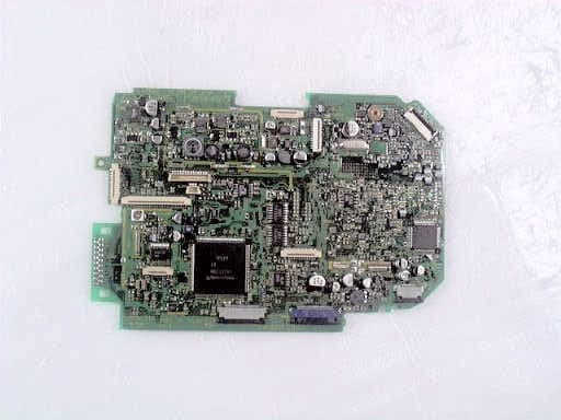
Click to zoom
Application Details
- Equipment Class
- JBP - Part 15 Class B Computing Device Peripheral
- Date of Grant
- Nov 01, 2000
- Application Purpose
- Original Equipment
- Date of Application
- Oct 12, 2000
- Equipment Note
- Video Camera
- Country
- United States
Documents & Files
Document Text
Text extracted from the exhibit documents filed with the FCC. Open a document above to read the original.
Attestation Statements
Description of Application Model FCC ID : ACJ927137K OUR REF. : MKES00-F013 MODEL NO.: PV-L751D Application model is as below. FCC ID: ACJ927137K Application name: Video Camera Grantee name: Matsushita Electric Industrial Co., Ltd. Manufacturer: Matsushita-Kotobuki Electronics Ind. Ltd. Model No.: PV-L751D Brand name: Panasonic Cabinet Material: Plastics
Attestation Statements
Description of Class B PeripheralsEXHIBIT #: 4-1 FCC ID: ACJ927137K OUR REF.: MKES00-F013 MODEL NO.: PV-L751D Page 1/2 Technical Specification Power Source : DC 6V Power Consumption : 8.5W Video Recording System: EIA Standard (525 lines, 60 fields) NTSC color signal Frequency generated or used : 10 Hz - 28.6 MHz Operating Temperature: 0 C - 40 C Operating Humidity: 10 % - 75 % Device Operation DescriptionEXHIBIT #: 4-1 FCC ID : ACJ927137K OUR REF.: MKES00-F013 MODEL NO.: PV-L751D Page 2/2 Performance Explanation of Video Camera Light on CCD through the lens is converted into the electric analog signal, and it goes to the Camera Process. Through the Camera Process, such analog signal is converted into the digital signal via built-in A/D Converter. And its digital signal is converted into NTSC signal, then it is converted again into analog signal to VCR Process. It is output through VCR Process to TV Monitor. The route of signal from Camcorder to PC: CCD Output signal which was input to Camera Process is A/D converted. It is divided prior to NTSC Process and is led, via digital output of Camera Process, to Camera CPU. Then it is converted in the CPU into RS232C signal and output to RS232C Driver. It is voltage-converted by RS232C Driver and goes to PC through RS232C Cable. Like, Control signal and Frozen Image Picture goes from PC to Camcorder. And the image data through Camera CPU is stored in the CF Card. On the other hand, the data stored in the CF Card is output on the Monitor TV through the same BUS line via Camera CPU, Camera Process and VCR Process. This CF Card is a removable data storage media. Through this data transmission system, playback picture data cannot be transmitted because this system is just for transmitting the image data interactively between Camera Signal Process IC and PC. Through this data transmission system, playback picture data cannot be transmitted because this system is just for transmitting the image data interactively between Camera Signal Process IC and PC.
Attestation Statements
EXHIBIT #: 3-2 FCC ID: ACJ927137K OUR REF.: MKES00-F013 MODEL NO.: PV-L751D Block Diagram of System for Measurements Page 1 / 3 (1) Printer Computer Mouse Monitor AC Adaptor (7) (5) (6) (8) (4) Earphone Video Camera (EUT) Microphone S-VCR (2) (3) EXHIBIT #: 3-2 FCC ID: ACJ927137K OUR REF.: MKES00-F013 MODEL NO.: PV-L751D Page 2 / 3 Type of Interface Cable (1)Power Cord (2)Audio/Video Cable (1.5 m): Shielded Cable ; Circular Cable (3)DC Cable (2.0 m): Circular Cable (4)PC Interface cable (2.0 m): Shielded Cable with Ferrite Cores ; Circular Cable (Serial Cable) (5)Monitor Cable (1.5 m) : Shielded Cable with Ferrite Cores ; Circular Cable (Permanently attached to the Monitor) (6)Printer Cable (1.5 m): Shielded Cable ; Circular Cable (Parallel Cable) (7)Keyboard Cable (1.7 m): Shielded Cable ; Circular Cable (Permanently attached to the Keyboard) (8)Mouse Cable (1.8 m): Shielded Cable ; Circular Cable (Permanently attached to the Mouse) EXHIBIT #: 3-2 FCC ID: ACJ927137K OUR REF.: MKES00-F013 MODEL NO.: PV-L751D Page 3 / 3 Description Video CameraModel No. : PV-L751D (Application Device) Trade Name : Panasonic FCC ID : ACJ927137K AC AdaptorModel No.: PV-A19 (For Video Camera)Trade Name: Panasonic MicrophoneModel No.: ECM-K57 Trade Name: SONY Monitor Model No.: 500-069EV (Certified Device) Trade Name: Gateway FCC ID: BEJCS592 Computer Model No. : DCM (DoC Device) Trade Name : DELL Computer Corporation KeyboardModel No.: SK-1000REW (Certified Device)Trade Name: DELL Computer Corporation FCC ID: GYUR36SK Mouse Model No. : 90741 (Certified Device) Trade Name : Microsoft Corporation FCC ID : C3KKMP3 PrinterModel No.: P-200JD (Certified Device)Trade Name: Panasonic FCC ID: IUO5LU0002 S-VCR Model No. : PV-VS4820 (DoC Device) Trade Name : Panasonic
Block Diagram
EXHIBIT #: 4-2 FCC ID: ACJ927137K OUR REF.: MKES00-F013 MODEL NO.: PV-L751D Page 1/2 Block Diagram EXHIBIT #: 4-2 FCC ID: ACJ927137K OUR REF.: MKES00-F013 MODEL NO.: PV-L751D Page 2/2 List of Frequency CLOCK of Video Camera CIRCUIT NameCLOCK Timing Generator28.6 MHz CCD9.5 MHz Camera Process9.5 MHz Camera I/F9.5 MHz VCR Process14.3 MHz CYL Head629 KHz - 4 MHz RS-232C10 – 115 KHz CF Card1 MHz Power500 KHz Timer Clock32.0 KHz VCR System CPU14.3 MHz EVF Process (PLL)10.38 MHz
ID Label/Location Info
EXHIBIT #: 1 FCC ID : ACJ927137K OUR REF. : MKES00-F013 MODEL NO.: PV-L751D Sample of FCC Identifier FCC Statements for compliance with FCC Rules Part 15 in User's Manual EXHIBIT #: 2 FCC ID : ACJ927137K OUR REF. : MKES00-F013 MODEL NO.: PV-L751D FCC IDENTIFIER
Internal Photos
EXHIBIT #: FCC ID: ACJ927137K OUR REF. : MKES00-F013 MODEL NO.: PV-L751D Sheet 1 of 14 Sheets EXHIBIT #: FCC ID: ACJ927137K OUR REF. : MKES00-F013 MODEL NO.: PV-L751D Sheet 2 of 14 Sheets EXHIBIT #: FCC ID: ACJ927137K OUR REF. : MKES00-F013 MODEL NO.: PV-L751D Sheet 3 of 14 Sheets Camera Main PCB (Top view) PC Terminal PCB (Bottom view) To PC Connector PC Terminal PCB (Top View) EXHIBIT #: FCC ID: ACJ927137K OUR REF. : MKES00-F013 MODEL NO.: PV-L751D Sheet 4 of 14 Sheets Camera Main PCB (Top view) Camera Main PCB (Top view) EXHIBIT #: FCC ID: ACJ927137K OUR REF. : MKES00-F013 MODEL NO.: PV-L751D Sheet 5 of 14 Sheets Camera Main PCB (Bottom view) Battery Catcher PCB (Bottom view) EXHIBIT #: FCC ID: ACJ927137K OUR REF. : MKES00-F013 MODEL NO.: PV-L751D Sheet 6 of 14 Sheets Battery Catcher PCB (Top view) Battery Catcher PCB (Top view) EXHIBIT #: FCC ID: ACJ927137K OUR REF. : MKES00-F013 MODEL NO.: PV-L751D Sheet 7 of 14 Sheets LCD LCD EXHIBIT #: FCC ID: ACJ927137K OUR REF. : MKES00-F013 MODEL NO.: PV-L751D Sheet 8 of 14 Sheets LCD PCB (Top view) LCD PCB (Top view) EXHIBIT #: FCC ID: ACJ927137K OUR REF. : MKES00-F013 MODEL NO.: PV-L751D Sheet 9 of 14 Sheets LCD PCB (Bottom view) LCD (Bottom view) EXHIBIT #: FCC ID: ACJ927137K OUR REF. : MKES00-F013 MODEL NO.: PV-L751D Sheet 10 of 14 Sheets LCD Electronic View Finder (Top view) EXHIBIT #: FCC ID ACJ927137K OUR REF. : MKES00-F013 : V-L751D Sheet 11 14 Sheets Electronic View Finder (Top view) Electronic View Finder (Bottom view) EXHIBIT #: FCC ID: ACJ927137K OUR REF. : MKES00-F013 MODEL NO.: PV-L751D Sheet 12 of 14 Sheets AC Adaptor (PV-A19) AC Adaptor (PV-A19) EXHIBIT #: FCC ID: ACJ927137K OUR REF. : MKES00-F013 MODEL NO.: PV-L751D Sheet 13 of 14 Sheets AC Adaptor PCB (Top view) AC Adaptor PCB (Top view) EXHIBIT #: FCC ID: ACJ927137K OUR REF. : MKES00-F013 MODEL NO.: PV-L751D Sheet 14 of 14 Sheets AC Adaptor PCB (Top view) AC Adaptor PCB (Bottom view)
Test Report
EXHIBIT #: 3-1 FCC ID: ACJ927137K OUR REF.: MKES00-F013 MODEL NO.: PV-L751D Sheet 3 of 10 Sheets 1) 15.107 Power Line Conducted Voltage Meter Reading (dBuV)Interference (dBuV) Freq. (MHz) 1-end & Grounded The other- End & Gro. LISN Factor (dB) 1-end & Grounded The other- End & Gro 3.9839.738.90.340.039.2 5.2636.435.60.436.836.0 5.6934.131.20.434.531.6 5.9533.431.60.433.832.0 19.0031.631.50.732.332.2 28.6432.630.31.033.631.3 Note: 1. Sample calculation at 1-end & Gro. 3.98 MHz; 39.7 + 0.3 = 40.0 (dBuV) 2. Measuring Instruments: a) Field strength meter - Kyoritsu Electric Work Co., Ltd. Model : KNM-2403 (1) Detector function: CISPR Q-Peak (2) IF band width : 9 kHz (3) Input impedance : 50 ohms b) Line impedance stabilized network (LISN) - Kyoritsu Electric Work CO., Ltd. Model : KNW-406, KNW-407 50 ohms / 50 uH network c) Test Signal Generator- Shibasoku Co., Ltd. (Multi Burst) Model : 205 3. The spectrum was checked from 0.45 MHz to 30 MHz and the six highest emissions relative to the appropriate limit were measured and reported. EXHIBIT #: 3-1 FCC ID: ACJ927137K OUR REF.: MKES00-F013 MODEL NO.: PV-L751D Sheet 4 of 10 Sheets 2) 15.109 Radiated Emission Meter Reading Open Volt. (dBuV) Emission at 3 meters (dBuV) Freq. (MHz) Horiz.Vert. Correction Factor (Db) Open Vol. Horiz.Vert. 76.3625.512.2 8.133.620.3 114.5421.8 7.114.436.221.5 200.4517.0 8.319.436.427.7 219.5519.3 9.920.139.430.0 257.7318.4 8.821.139.529.9 381.8120.111.219.439.530.6 Note: 1. Sample calculation at Horiz., 76.36 MHz ; 25.5 + 8.1 = 33.6 (dBuV/m) 2. Measuring Instruments: a) Field strength meter - Hewlett Packard company Model: HP 8546A (1) Frequency range: 9 kHz to 6.5 GHz (2) RF Input: 50 ohm (3) IF band width: 200 Hz/ 9 kHz/ 120 kHz/ 1MHz (4) Detector function: Average/CISPR Q-Peak/Peak b) Receiving antenna- Schwarzbeck Model: VHA9103 30 - 300 MHz Model: UHALP9108A 300 - 1000 MHz 3. The Spectrum was checked from 30 MHz to 1000 MHz and the six highest emissions relative to the appropriate limit were measured and reported. emissions relative to the appropriate limit were measured and reported. EXHIBIT #: 3-1 FCC ID: ACJ927137K OUR REF.: MKES00-F013 MODEL NO.: PV-L751D Sheet 5 of 10 Sheets 15.107 POWER LINE CONDUCTED VOLTAGE - CONFIGURATION OF THE EQUIPMENT UNDER TEST - ( Arrangement of interface cable on the test table ) EXHIBIT #: 3-1 FCC ID: ACJ927137K OUR REF.: MKES00-F013 MODEL NO.: PV-L751D Sheet 6 of 10 Sheets 15.109 RADIATED EMISSION - CONFIGURATION OF THE EQUIPMENT UNDER TEST - ( Arrangement of interface cable on the test table ) EXHIBIT #: 3-1 FCC ID: ACJ927137K OUR REF.: MKES00-F013 MODEL NO.: PV-L751D Sheet 7 of 10 Sheets 15.109 RADIATED EMISSION - CONFIGURATION OF THE EQUIPMENT UNDER TEST - ( Arrangement of interface cable on the test table ) EXHIBIT #: 3-1 FCC ID: ACJ927137K OUR REF.: MKES00-F013 MODEL NO.: PV-L751D Sheet 8 of 10 Sheets EXHIBIT #: 3-1 FCC ID: ACJ927137K OUR REF.: MKES00-F013 MODEL NO.: PV-L751D Sheet 9 of 10 Sheets EXHIBIT #: 3-1 FCC ID: ACJ927137K OUR REF.: MKES00-F013 MODEL NO.: PV-L751D Sheet 10 of 10 Sheets
Contact Information
Applicant
Ben Botros(Project Manager)
Technical Contact
Matsushita Electric Corp of AmericaRichard Mullen
[email protected]201-348-7758
one panasonic way 4b-8 · Secaucus, New Jersey · United States
Test Firm
Panasonic Healthcare Co., LtdOsamu Kobashi
[email protected]81-897-56-1111
Technical Specifications
| # | Rule Parts | Frequency Range | Power Output |
|---|---|---|---|
| 1 | 15B | - | - |
Other Applications from Panasonic Corporation of North America
ACJ-EAH-A1000
Aug 19, 2026Digital Wireless Stereo Headphones
Equipment Class
DSS - Part 15 Spread Spectrum TransmitterACJ9TGFZVNF3G1
Jun 16, 2026Contactless Smart Card Reader
Equipment Class
DXX - Part 15 Low Power Communication Device Transmitter
ACJ932AM2301
Jan 29, 2025Car AV Control Unit for CDC
Equipment Class
DTS - Digital Transmission SystemACJ96NKX-TGEA60B
Aug 13, 2024DECT Handset
Equipment Class
PUE - Part 15 Unlicensed PCS portable Tx held to earACJ96NKX-TGE630B
Aug 12, 2024DECT Base Unit
Equipment Class
PUB - Part 15 Unlicensed PCS Base Station