ACJ932AT2301Wireless Charger
Panasonic Corporation of North America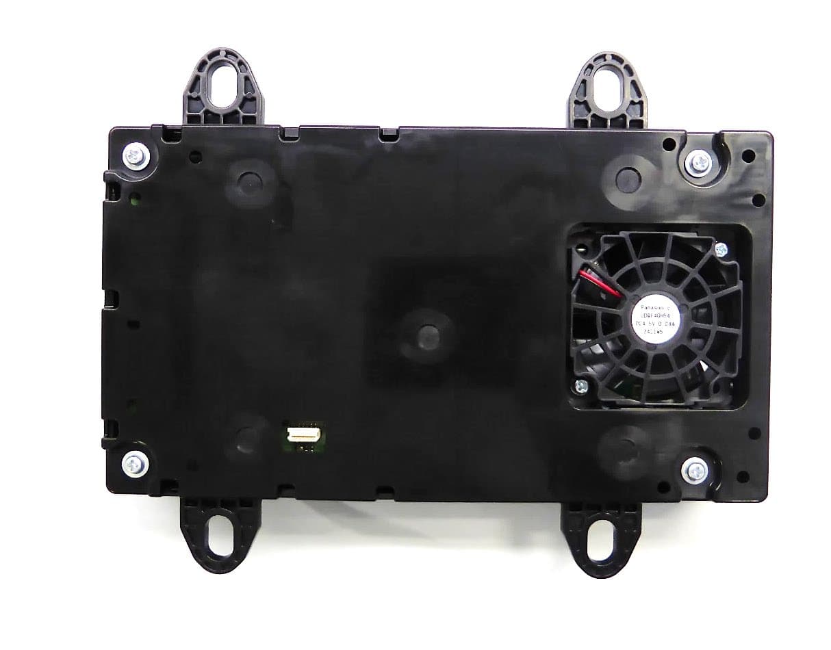
Click to zoom
Application Details
- Equipment Class
- 8CC - Part 18 Consumer Device
- Date of Grant
- Aug 25, 2022
- Application Purpose
- Original Equipment
- Date of Application
- Aug 25, 2022
- Equipment Note
- Wireless Charger
- Frequency Range
- 0.11640000 - 0.13220000
- Country
- United States
Documents & Files
Document Text
Text extracted from the exhibit documents filed with the FCC. Open a document above to read the original.
Users Manual
Wireless charger user’s manual A portable device can be charged by just placing “qi” standard wireless charge compatible portable devices according to the Wireless Power Consortium, such as portable phones, smart phones, etc., on the charge area. This function can not be used with portable devices that are larger than the charging area. Also, depending on the portable device, it may not operate as normal. Please read the operation manual for portable devices to be used. ■The “qi” symbol The “qi” symbol is a trademark of the Wireless Power Consortium. ■Namefor all parts (1) Operation indicator light (2) Charge area ■Using the wireless charger Use the ACC KEY of the car to turn the Wireless charger power ON/OFF. Place the charging side of the portable device (etc. mobile phone) down. When charging, the operation indicator light (orange) comes on. If charging is not occurring, try placing the portable device as close to the center of the charging area as possible. When charging is complete, the operation indicator light (green) comes on. Recharging function ・When charging is compatible and after a fixed timed in the charge suspension state, charging restarts. ・Whenthe portable device is moved, charging is stopped for a moment and then it restarts. ■Lighting conditions of operation indicator light *Depending on the portable device, there are cases where the operation Indicator light will continue being. Operation indicator lightConditions Turning off When the wireless charger power supply is off. On standby (charging possible state) When charging is complete. * Green (comes on) When placing the portable device on the charging area (detecting the portable device) Charging Orange (comes on) (2) (1) Since this device is always used with vehicle, it is not sold to general end users separately. Therefore there is no user manual of this device by alone. The following statements must be described on the user manual of the vehicle; [For FCC] This device complies with part 15 and part 18 of the FCC Rules. Operation is subject to the following two conditions: (1) This device may not cause harmful interference, and (2) this device must accept any interference received, including interference that may cause undesired operation. FCC CAUTION: Changes or modifications not expressly approved by the party responsible for compliance could void the user’s authority to operate the equipment. This equipment has been tested and found to comply with the limits for a wireless power charger, pursuant to part 18 of the FCC Rules. This equipment generates, uses and can radiate radio frequency energy and, if not installed and used in accordance with the instructions, may cause harmful interference to radio communications. However, there is no guarantee that interference will not occur in a particular installation. If this equipment does cause harmful interference to radio communications, which can be determined by turning the equipment off and on, the user is encouraged to try to correct the interference by one or more of the following measures: -Reorient or relocate the receiving antenna. -Increase the separation between the equipment and receiver. -Connect the equipment into an outlet on a circuit different from that to which the receiver is connected. This equipment complies with FCC radiation exposure limits set forth for an uncontrolled environment and meets the FCC radio frequency (RF) Exposure Guidelines. This equipment should be installed and operated keeping the radiator at least 20cm or more away from person’s body. The contact information for maintenance is described in the car manual by the manufacturer of the car in which this wireless charger is installed. [For ISED] IC : 216J-AT2301 This device contains licence-exempt transmitter(s)/receiver(s) that comply with Innovation, Science and Economic Development Canada’s licence-exempt RSS(s). Operation is subject to the following two conditions: 1.This device may not cause interference. 2.This device must accept any interference, including interference that may cause undesired operation of the device. This equipment should be operated keeping at least 10cm or more away from person’s body. L’émetteur/récepteurexempt de licencecontenudansle présentappareilest conformeaux CNR d’Innovation, Sciences et Développementéconomique Canada applicablesaux appareilsradio exempts de licence. L’exploitationest autoriséeaux deux conditions suivantes: 1.L’appareil ne doitpas produirede brouillage; 2.L’appareil doitaccepter tout brouillageradioélectriquesubi, mêmesi le brouillageestsusceptible d’en compromettrele fonctionnement. Cet équipement doit être utilisé en gardant au moins 10 cm ou plus loin du corps de la personne.
Cover Letter(s)
Panasonic Corporation of No rth America Two Riverf ront Plaza, 9 th Floor, Newark, NJ 07102-5490 Tel/Fax: 201-348-7760 / [email protected] Ben Botros, Manager – Reg ulatory & Compliance Panasonic Corporation of North America FCC Agent Authorization Letter August 8, 2022 PAS-22-F009 UL Verification Services Inc. 47173 Benicia Street, Fremont, CA 94538 Re: Original Certification for Wireless Charger, Model AT2301 for FCC Part 15C and 18 under FCC ID: ACJ932AT2301 To Whom It May Concern: Please be advised Panasonic Corporation of North America hereby authorizes Rie Fujiwara of UL Japan, Inc. (“UL”) to act on our behalf for this single filing and for a period of one year from the date of this letter. Any and all acts carried out by UL on our behalf shall have the same effect as acts of our own. We certify that we are not subject to denial of federal benefits, which includes FCC benefits, pursuant to Section 5301 of the Anti-Drug Abuse ACT of 1988, 21 U.S.C. 862. Further, no party, as defined in 47 CFR 1.2002(b), to the application is subject to denial of federal benefits, that includes FCC benefits. Further, this application for equipment authorization has not been submitted to another TCB for Certification. Equipment Name: FCC ID: FCC Rule Parts: Frequency Band: Charging Frequency: Applicant & Grantee: FRN Number: Wireless Charger \ Model AT2301 ACJ932AT2301 FCC Part 15, Subpart 15C and 18 116 kHz ~ 133 kHz, 120.3kHz, 127.0 kHz, 127.5 kHz and 116.4 kHz ~ 132.2kHz Panasonic Corporation of North America Two Riverfront Plaza, 9 th Floor, Newark, NJ 07102-5490 USA 0003762242 Please advise the u ndersigned should you have any questions or comments. Authorized by, Ben Botros Manager – Regulatory & Compliance Panasonic Corporation of North America
Cover Letter(s)
Panasonic Corporation of No rth America Two Riverf ront Plaza, 9 th Floor, Newark, NJ 07102-5490 Tel/Fax: 201-348-7760 / [email protected] Ben Botros, Manager – Reg ulatory & Compliance Panasonic Corporation of North America Request for Permanent Confidentiality Au gust 8, 2022 PAS -22-F009 UL Verification Services Inc. 47173 Benicia Street, Fremont, CA 94538 Re: Original Certification for Wireless Charger, Model AT2301 for FCC Part 15C an d 18 under FCC ID: ACJ932AT2301 To Whom It May Concern: In a ccordance with provisions of Sections 0.457 and 0.459 of the Commission’s Rules and Section 552(b)(4) of the Fr eedom of Information Act, we request permanent co nfidentiality for the below indicated exhibits. These exhibits contain proprietary, confidential and/or trade se cret materials, which would not be routinely made available for public inspection. •Sch emat ic Diagrams •Block Diagram •Theorty of Operation Tha nk you for your attention to this matter. Aut horized by, Ben Botros Manager – Regulatory & Compliance Panasonic Corporation of North America
External Photos
External photoConfidential 105 mm 85mm External photoConfidential External photoConfidential External photoConfidential External photoConfidential
ID Label/Location Info
Wireless Charger Label position
ID Label/Location Info
Wireless Charger Label The following text (statement of conformity to 15C) will be displayed in the manual because the size of the product is small and there is no space to describe it. This device complies with part 15 of the FCC Rules. Operation is subject to the following two conditions: (1) This device may not cause harmful interference, and (2) this device must accept any interference received, including interference that may cause undesired operation. LABEL-1 M/N.*********** S/N. ******** R/N. AT2301 LABEL-2 Model Name : Wireless charger FCC ID: ACJ932AT2301 IC: 216J-AT2301 Panasonic Automotive Systems Co., Ltd. Made in ***************
Internal Photos
Internal photoConfidential Wireless Module Internal photoConfidential Internal photoConfidential Internal photoConfidential Internal photoConfidential Internal photoConfidential Primary Coil
Internal Photos
MAIN PWB photoConfidential Wireless Module Wireless Module photoConfidential
Test Report
Test report No. :14298319H Page : 1 of 49 UL Japan, Inc. Ise EMC Lab. 4383-326 Asama-cho, Ise-shi, Mie-ken 516-0021 Japan / +81-596-24-8999 EMI TEST REPORT Test Report No.: 14298319H Customer Panasonic Automotive Systems Co., Ltd. Description of EUT Wireless Charger Model Number of EUT AT2301 FCC ID ACJ932AT2301 Test Regulation FCC Part 18 Test Result Complied (Refer to SECTION 3) Issue Date July 11, 2022 Remarks - Representative Test Engineer Approved By Hiroyuki Furutaka Engineer Tsubasa Takayama Leader CERTIFICATE 5107.02 The testing in which "Non-accreditation" is displayed is outside the accreditation scopes in UL Japan, Inc. There is no testing item of "Non-accreditation". Report Cover Page - Form-ULID-003532 (DCS:13-EM-F0429) Issue# 21.0 Test report No. :14298319H Page : 2 of 49 UL Japan, Inc. Ise EMC Lab. 4383-326 Asama-cho, Ise-shi, Mie-ken 516-0021 Japan / +81-596-24-8999 ANNOUNCEMENT REVISION HISTORY Original Test Report No.: 14298319H Revision Test Report No. Date Page Revised Contents - (Ori ginal) 14298319H July 11, 2022 - This test report shall not be reproduced in full or partial, without the written approval of UL Japan, Inc. The results in this report appl y only to the sample tested. This sample tested is in compliance with the limits of the above re gulation. The test results in this test report are traceable to the national or international standards. This test report must not be used by the customer to claim product certification, approval, or endorsement by the A2LA accreditation bod y. This test report covers Radio technical requirements. It does not cover administrative issues such as Manual or non-Radio test related Requirements. (if applicable) The all test items in this test report are conducted b y UL Japan, Inc. Ise EMC Lab. The opinions and the interpretations to the result of the description in this report are outside scopes where UL Japan, Inc. has been accredited. The information provided from the applicant for this report is identified in Section 1. For test report(s) referred in this report, the latest version (includin g any revisions) is always referred. Test report No. :14298319H Page : 3 of 49 UL Japan, Inc. Ise EMC Lab. 4383-326 Asama-cho, Ise-shi, Mie-ken 516-0021 Japan / +81-596-24-8999 Reference: Abbreviations (Including words undescribed in this report) A2LA The American Association for Laboratory Accreditation ICES Interference-Causing Equipment Standard AC Alternating Current IEC International Electrotechnical Commission AFH Adaptive Frequency Hopping IEEE Institute of Electrical and Electronics Engineers AM Amplitude Modulation IF Intermediate Frequency Amp, AMP Amplifier ILAC International Laboratory Accreditation Conference ANSI American National Standards Institute ISED Innovation, Science and Economic Development Canada Ant, ANT Antenna ISO International Organization for Standardization AP Access Point JAB Japan Accreditation Board ASK Amplitude Shift Keying LAN Local Area Network Atten., ATT Attenuator LIMS Laboratory Information Management System AV Average MCS Modulation and Coding Scheme BPSK Binary Phase-Shift Keying MRA Mutual Recognition Arrangement BR Bluetooth Basic Rate N/A Not Applicable BT Bluetooth NIST National Institute of Standards and Technology BT LE Bluetooth Low Energy NS No signal detect. BW BandWidth NSA Normalized Site Attenuation Cal Int Calibration Interval NVLAP National Voluntary Laboratory Accreditation Pro gram CCK Complementary Code Keying OBW Occupied Band Width Ch., CH Channel OFDM Orthogonal Frequency Division Multiplexing CISPR Comite International Special des Perturbations Radioelectri ques P/M Power meter CW Continuous Wave PCB Printed Circuit Board DBPSK Differential BPSK PER Packet Error Rate DC Direct Current PHY Physical Layer D-factor Distance factor PK Peak DFS Dynamic Frequency Selection PN Pseudo random Noise DQPSK Differential QPSK PRBS Pseudo-Random Bit Sequence DSSS Direct Sequence Spread Spectrum PSD Power Spectral Density EDR Enhanced Data Rate QAM Quadrature Amplitude Modulation EIRP, e.i.r.p. Equivalent Isotropically Radiated Power QP Quasi-Peak EMC ElectroMagnetic Compatibility QPSK Quadri-Phase Shift Keying EMI ElectroMagnetic Interference RBW Resolution Band Width EN European Norm RDS Radio Data System ERP, e.r.p. Effective Radiated Power RE Radio Equipment EU European Union RF Radio Frequency EUT Equipment Under Test RMS Root Mean Square Fac. Factor RSS Radio Standards Specifications FCC Federal Communications Commission Rx Receiving FHSS Frequency Hopping Spread Spectrum SA, S/A Spectrum Analyzer FM Frequency Modulation SG Signal Generator Freq. Frequency SVSWR Site-Voltage Standing Wave Ratio FSK Frequency Shift Keying TR Test Receiver GFSK Gaussian Frequency-Shift Keying Tx Transmitting GNSS Global Navigation Satellite System VBW Video BandWidth GPS Global Positioning System Vert. Vertical Hori. Horizontal WLAN Wireless LAN Test report No. :14298319H Page : 4 of 49 UL Japan, Inc. Ise EMC Lab. 4383-326 Asama-cho, Ise-shi, Mie-ken 516-0021 Japan / +81-596-24-8999 CONTENTS PAGE SECTION 1: Customer Information .................................................................................................................. 5 SECTION 2: Equipment Under Test (EUT) ...................................................................................................... 5 SECTION 3: Test specification, procedures & results ...................................................................................... 6 SECTION 4: Operation of EUT during testing ................................................................................................. 8 SECTION 5: Radiated Emission ....................................................................................................................... 11 APPENDIX 1: Test data ..................................................................................................................................... 14 Radiated Emissi…
Text truncated - open the document above for the full version.
Test Report
Test report No. : 14298325H Page : 1 of 51 UL Japan, Inc. Ise EMC Lab. 4383-326 Asama-cho, Ise-shi, Mie-ken 516-0021 Japan / +81-596-24-8999 MPE TEST REPORT Test Report No.: 14298325H Customer Panasonic Automotive Systems Co., Ltd. Description of EUT Wireless Charger Model Number of EUT AT2301 FCC ID ACJ932AT2301 Test Regulation FCC rule §1.1310 Radiofrequency radiation exposure limits. Test Result Complied (Refer to SECTION 3) Issue Date July 11, 2022 Remarks *This test report has issued for MPE testing by wireless charger according to KDB 680106 D01 v03r01. Representative Test Engineer Approved By Hiroyuki Furutaka Engineer Tsubasa Takayama Leader CERTIFICATE 5107.02 The testing in which "Non-accreditation" is displayed is outside the accreditation scopes in UL Japan, Inc. There is no testing item of "Non-accreditation". Re port Cover Page - Form-ULID-003532 (DCS:13-EM-F0429) Issue# 21.0 Test report No. : 14298325H Page : 2 of 51 UL Japan, Inc. Ise EMC Lab. 4383-326 Asama-cho, Ise-shi, Mie-ken 516-0021 Japan / +81-596-24-8999 ANNOUNCEMENT REVISION HISTORY Original Test Report No.: 14298325H Revision Test Report No. Date Page Revised Contents - (Ori ginal) 14298325H July 11, 2022 - This test report shall not be reproduced in full or partial, without the written approval of UL Japan, Inc. The results in this report appl y only to the sample tested. This sample tested is in compliance with the limits of the above re gulation. The test results in this test report are traceable to the national or international standards. This test report must not be used by the customer to claim product certification, approval, or endorsement by the A2LA accreditation bod y. This test report covers MPE technical requirements. It does not cover administrative issues such as Manual or non-MPE test related Requirements. (if applicable) The all test items in this test report are conducted b y UL Japan, Inc. Ise EMC Lab. The opinions and the interpretations to the result of the description in this report are outside scopes where UL Japan, Inc. has been accredited. The information provided from the applicant for this report is identified in Section 1. For test report(s) referred in this report, the latest version (includin g any revisions) is always referred. Test report No. : 14298325H Page : 3 of 51 UL Japan, Inc. Ise EMC Lab. 4383-326 Asama-cho, Ise-shi, Mie-ken 516-0021 Japan / +81-596-24-8999 Reference: Abbreviations (Including words undescribed in this report) A2LA The American Association for Laboratory Accreditation ICES Interference-Causing Equipment Standard AC Alternating Current IEC International Electrotechnical Commission AFH Adaptive Frequency Hopping IEEE Institute of Electrical and Electronics Engineers AM Amplitude Modulation IF Intermediate Frequency Amp, AMP Amplifier ILAC International Laboratory Accreditation Conference ANSI American National Standards Institute ISED Innovation, Science and Economic Development Canada Ant, ANT Antenna ISO International Organization for Standardization AP Access Point JAB Japan Accreditation Board ASK Amplitude Shift Keying LAN Local Area Network Atten., ATT Attenuator LIMS Laboratory Information Management System AV Average MCS Modulation and Coding Scheme BPSK Binary Phase-Shift Keying MRA Mutual Recognition Arrangement BR Bluetooth Basic Rate N/A Not Applicable BT Bluetooth NIST National Institute of Standards and Technology BT LE Bluetooth Low Energy NS No signal detect. BW BandWidth NSA Normalized Site Attenuation Cal Int Calibration Interval NVLAP National Voluntary Laboratory Accreditation Pro gram CCK Complementary Code Keying OBW Occupied Band Width Ch., CH Channel OFDM Orthogonal Frequency Division Multiplexing CISPR Comite International Special des Perturbations Radioelectri ques P/M Power meter CW Continuous Wave PCB Printed Circuit Board DBPSK Differential BPSK PER Packet Error Rate DC Direct Current PHY Physical Layer D-factor Distance factor PK Peak DFS Dynamic Frequency Selection PN Pseudo random Noise DQPSK Differential QPSK PRBS Pseudo-Random Bit Sequence DSSS Direct Sequence Spread Spectrum PSD Power Spectral Density EDR Enhanced Data Rate QAM Quadrature Amplitude Modulation EIRP, e.i.r.p. Equivalent Isotropically Radiated Power QP Quasi-Peak EMC ElectroMagnetic Compatibility QPSK Quadri-Phase Shift Keying EMI ElectroMagnetic Interference RBW Resolution Band Width EN European Norm RDS Radio Data System ERP, e.r.p. Effective Radiated Power RE Radio Equipment EU European Union RF Radio Frequency EUT Equipment Under Test RMS Root Mean Square Fac. Factor RSS Radio Standards Specifications FCC Federal Communications Commission Rx Receiving FHSS Frequency Hopping Spread Spectrum SA, S/A Spectrum Analyzer FM Frequency Modulation SG Signal Generator Freq. Frequency SVSWR Site-Voltage Standing Wave Ratio FSK Frequency Shift Keying TR Test Receiver GFSK Gaussian Frequency-Shift Keying Tx Transmitting GNSS Global Navigation Satellite System VBW Video BandWidth GPS Global Positioning System Vert. Vertical Hori. Horizontal WLAN Wireless LAN Test report No. : 14298325H Page : 4 of 51 UL Japan, Inc. Ise EMC Lab. 4383-326 Asama-cho, Ise-shi, Mie-ken 516-0021 Japan / +81-596-24-8999 CONTENTS PAGE SECTION 1: Customer Information ................................................................................................... 5 SECTION 2: Equipment Under Test (EUT) ....................................................................................... 5 SECTION 3: Test specification, procedures & results ....................................................................... 6 SECTION 4: Operation of EUT during testing .................................................................................. 9 SECTION 5: MPE Limit [KDB 680106 Section 3) (FCC §1.1310)] ................................................ 12 APPENDIX 1: Test data ..........................................................................................................…
Text truncated - open the document above for the full version.
Test Setup Photos
Test report No. :14298319H Page : 45 of 49 UL Japan, Inc. Ise EMC Lab. 4383-326 Asama-cho, Ise-shi, Mie-ken 516-0021 Japan / +81-596-24-8999 APPENDIX 3: Photographs of test setup Radiated Emission (Mode 1 to 3) Photo 1 Photo 2 Test report No. :14298319H Page : 46 of 49 UL Japan, Inc. Ise EMC Lab. 4383-326 Asama-cho, Ise-shi, Mie-ken 516-0021 Japan / +81-596-24-8999 Radiated Emission (Mode 4 to 6) Photo 1 Photo 2 Test report No. :14298319H Page : 47 of 49 UL Japan, Inc. Ise EMC Lab. 4383-326 Asama-cho, Ise-shi, Mie-ken 516-0021 Japan / +81-596-24-8999 Radiated Emission (Mode 7 to 15) Photo 1 Photo 2 Test report No. :14298319H Page : 48 of 49 UL Japan, Inc. Ise EMC Lab. 4383-326 Asama-cho, Ise-shi, Mie-ken 516-0021 Japan / +81-596-24-8999 Worst Case Position BPP 5 W 120.30 kHz / 127.00 kHz / 127.50 kHz EPP 15 W 120.30 kHz / 127.00 kHz / 127.50 kHz Below 30 MHz: Z-axis Above 30 MHz: Horizontal: X-axis / Vertical: X-axis Below 30 MHz: X-axis Above 30 MHz: Horizontal: X-axis / Vertical: X-axis X-axis X-axis Y-axis Y-axis Z-axis Z-axis Test report No. :14298319H Page : 49 of 49 UL Japan, Inc. Ise EMC Lab. 4383-326 Asama-cho, Ise-shi, Mie-ken 516-0021 Japan / +81-596-24-8999 Worst Case Position Other frequency except for 120.30 kHz / 127.50 kHz / 127.00 kHz Below 30 MHz: Z-axis Above 30 MHz: Horizontal: X-axis / Vertical: X-axis X-axis Y-axis Z-axis End of Report
Test Setup Photos
Test report No. : 14298325H Page : 44 of 51 UL Japan, Inc. Ise EMC Lab. 4383-326 Asama-cho, Ise-shi, Mie-ken 516-0021 Japan / +81-596-24-8999 APPENDIX 3: Photographs of test setup Electromagnetic field [KDB 680106 Section 3) (FCC §1.1310)] Magnetic field strength_15 cm Top Front Rear Left Right Bottom Test report No. : 14298325H Page : 45 of 51 UL Japan, Inc. Ise EMC Lab. 4383-326 Asama-cho, Ise-shi, Mie-ken 516-0021 Japan / +81-596-24-8999 Magnetic field strength_20 cm Top Front Rear Left Right Bottom Test report No. : 14298325H Page : 46 of 51 UL Japan, Inc. Ise EMC Lab. 4383-326 Asama-cho, Ise-shi, Mie-ken 516-0021 Japan / +81-596-24-8999 Magnetic field strength_30 cm Top Front Rear Left Right Bottom Test report No. : 14298325H Page : 47 of 51 UL Japan, Inc. Ise EMC Lab. 4383-326 Asama-cho, Ise-shi, Mie-ken 516-0021 Japan / +81-596-24-8999 Magnetic field strength_40 cm Top Front Rear Left Right Bottom Test report No. : 14298325H Page : 48 of 51 UL Japan, Inc. Ise EMC Lab. 4383-326 Asama-cho, Ise-shi, Mie-ken 516-0021 Japan / +81-596-24-8999 Electromagnetic field [KDB 680106 Section 3) (FCC §1.1310)] Electric field strength_15 cm Top Front Rear Left Right Bottom Test report No. : 14298325H Page : 49 of 51 UL Japan, Inc. Ise EMC Lab. 4383-326 Asama-cho, Ise-shi, Mie-ken 516-0021 Japan / +81-596-24-8999 Electric field strength_20 cm Top Front Rear Left Right Bottom Test report No. : 14298325H Page : 50 of 51 UL Japan, Inc. Ise EMC Lab. 4383-326 Asama-cho, Ise-shi, Mie-ken 516-0021 Japan / +81-596-24-8999 Electric field strength_30 cm Top Front Rear Left Right Bottom Test report No. : 14298325H Page : 51 of 51 UL Japan, Inc. Ise EMC Lab. 4383-326 Asama-cho, Ise-shi, Mie-ken 516-0021 Japan / +81-596-24-8999 Electric field strength_40 cm Top Front Rear Left Right Bottom End of Report
Contact Information
Applicant
Ben Botros(Manager - Regulatory & Compliance)
Technical Contact
UL Japan, Inc.Tsubasa Takayama
[email protected]81-596-24-8999
4383-326 Asama-cho, Ise-shi · Mie-ken · Japan
Test Firm
UL Japan, Inc.(Ise)Takayuki Shimada
Technical Specifications
| # | Rule Parts | Frequency Range | Power Output |
|---|---|---|---|
| 4 | 18 | 0.1164 MHz - 0.1322 MHz | - |
Other Applications from Panasonic Corporation of North America
ACJ-EAH-A1000
Aug 19, 2026Digital Wireless Stereo Headphones
Equipment Class
DSS - Part 15 Spread Spectrum TransmitterACJ9TGFZVNF3G1
Jun 16, 2026Contactless Smart Card Reader
Equipment Class
DXX - Part 15 Low Power Communication Device Transmitter
ACJ932AM2301
Jan 29, 2025Car AV Control Unit for CDC
Equipment Class
DTS - Digital Transmission SystemACJ96NKX-TGEA60B
Aug 13, 2024DECT Handset
Equipment Class
PUE - Part 15 Unlicensed PCS portable Tx held to earACJ96NKX-TGE630B
Aug 12, 2024DECT Base Unit
Equipment Class
PUB - Part 15 Unlicensed PCS Base Station