ACJ932CY-BT100UVehicle Hands Free Kit with Bluetooth Transmitter
Panasonic Corporation of North America
Click to zoom
Application Details
- Equipment Class
- DSS - Part 15 Spread Spectrum Transmitter
- Date of Grant
- Dec 08, 2005
- Application Purpose
- Original Equipment
- Date of Application
- Dec 08, 2005
- Equipment Note
- Vehicle Hands Free Kit with Bluetooth Transmitter
- Frequency Range
- 2402.00000000 - 2480.00000000
- Country
- United States
Documents & Files
Document Text
Text extracted from the exhibit documents filed with the FCC. Open a document above to read the original.
Users Manual
2 English 3 Safety Information This pictograph intends to alert you to the pres- ence of important operating instructions and installation instructions. Failure to heed the instructions may result in severe injury or death. ■ Read the operating instructions for the unit and all other com- ponents of your car audio system carefully before using the system. They contain instructions about how to use the sys- tem in a safe and effective manner. Panasonic assumes no responsibility for any problems resulting from failure to observe the instructions given in this manual. ■ This manual uses pictographs to show you how to use the product safely and to alert you to potential dangers resulting from improper connections and operations. The meanings of the pictographs are explained below. It is important that you fully understand the meanings of the pictographs in order to use this manual and the system properly. Warning This pictograph intends to alert you to the pres- ence of important operating instructions and installation instructions. Failure to heed the instructions may result in injury or material dam- age. Caution Warning Observe the following warnings when using this unit. ❑ Comply with regulations Always comply with legal requirements and local restrictions when using this unit. ❑ Keep away from the medical devices. This unit and mobile phones can interfere with the function- ing of medical devices such as hearing aids or pacemakers. Failure to observe this may arise the malfunction of med- ical devices resulting in personal injury or death. ❑ The driver should not neither adjust the unit nor make a pair while driving. Adjusting the unit or making a pair of this unit and the mobile phone will distract the driver from looking ahead of the car and can cause accidents. Always stop the car in a safe location and use the parking brake before adjustment or making a pair. Warning ❑ Use the proper power supply (12 V). This product is designed for operation with a negative grounded 12 V DC battery system. Never operate this prod- uct with other battery systems, especially a 24 V DC battery system. ❑ Do not disassemble or modify the unit. Do not disassemble, modify the unit or attempt to repair the product yourself. If the product needs to be repaired, consult your dealer or an authorized Panasonic Servicenter. ❑ Do not use the unit when it is out of order. If the unit is out of order (no power, no sound) or in an abnormal state (has foreign objects in it, is exposed to water, is smoking, or smells), turn it off immediately and consult your dealer. ❑ Stop using this unit and mobile phone whenever requested. This unit shares the communication frequency with other private or public wireless communication equipment such as a wireless LAN and other wireless communication radios. You should stop using this unit whenever you are notified that your unit disturbs other wireless communication imme- diately. Observe the following warnings when installing. (including whole assembly of the devices for system up) ❑ Disconnect the lead from the negative (–) battery terminal before installation. Wiring and installation with the negative (–) battery terminal connected may cause electrical shock and injury due to a short circuit. Some cars equipped with the electrical safety system have specific procedures of battery terminal disconnection. FAILURE TO FOLLOW THE PROCEDURE MAY LEAD TO THE UNINTENDED ACTIVATION OF THE ELECTRICAL SAFETY SYSTEM RESULTING IN DAMAGE TO THE VEHICLE AND PERSONAL INJURY OR DEATH. ❑ Never use safety-related components for installa- tion, grounding, and other such functions. Do not use safety-related vehicle components (fuel tank, brake, suspension, steering wheel, pedals, airbag, etc.) for wiring or fixing the product or its accessories. ❑ Installing the product on the air bag cover or in a location where it interferes with airbag operation is prohibited. 4 English 5 Safety Information (continued) Warning ❑ Check for piping, gasoline tank, electric wiring, and other items before installing the product. If you need to open a hole in the vehicle chassis to attach or wire the product, first check where the wire harness, gaso- line tank, and electric wiring are located. Then open the hole from outside if possible. ❑ Never install the product in a location where it inter- feres with your field of vision. ❑ After installation and wiring, you should check the normal operation of other electrical equipment. The continuation of their using in abnormal conditions may cause fire, electrical shock or a traffic accident. ❑ In the case of installation to an airbag-equipping car, confirm warnings and cautions of the vehicle manufacturer before installation. ❑ Make sure the leads do not interfere with driving or getting in and out of the vehicle. ❑ Insulate all exposed wires to prevent short circuit- ing. ❑ If there seem to be something wrong with the sys- tem, park your car in a safe place and identify the abnormality. Caution Observe the following cautions when using this unit. ❑ Keep the sound volume at an appropriate level. Keep the volume level low enough to be aware of road and traffic conditions while driving. ❑ This unit is designed for use exclusively in automo- biles. ❑ Do not expose the unit to direct sunlight or exces- sive heat. Otherwise these will raise the interior temperature of the unit, and it may lead to smoke, fire, or other damage to the unit. ❑ Do not use the product where it is exposed to water, moisture, or dust. Exposure of the unit to water, moisture, or dust may lead to smoke, fire, or other damage to the unit. Make especially sure that the unit does not get wet in car washes or on rainy days. Observe the following cautions when installing. (including whole assembly of the devices for system up) ❑ Refer wiring and installation to qualified service personnel. Installation of this unit requires special skills and experience. For maximum safety, have it installed by your dealer. Pan…
Text truncated - open the document above for the full version.
External Photos
Matsushita Electric Industrial Co., Ltd. FCC ID:ACJ932CY-BT100U IC Number:216J-CYBT100U External Photo TOP VIEW Label is not final printing. BOTTOM VIEW Matsushita Electric Industrial Co., Ltd. FCC ID:ACJ932CY-BT100U IC Number:216J-CYBT100U FRONT VIEW REAR VIEW Matsushita Electric Industrial Co., Ltd. FCC ID:ACJ932CY-BT100U IC Number:216J-CYBT100U SIDE VIEW SIDE VIEW Matsushita Electric Industrial Co., Ltd. FCC ID:ACJ932CY-BT100U IC Number:216J-CYBT100U Connected Part
ID Label/Location Info
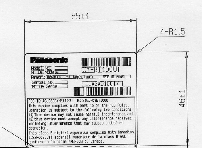
Label Location Label Location
Internal Photos
Matsushita Electric Industrial Co., Ltd. FCC ID:ACJ932CY-BT100U IC Number:216J-CYBT100U Internal Photo Built-in Antenna PCB TOP VIEW PCB BOTTOM VIEW Matsushita Electric Industrial Co., Ltd. FCC ID:ACJ932CY-BT100U IC Number:216J-CYBT100U Connected part
Test Report
UL Apex Co., Ltd. Head Office EMC Lab. 4383-326 Asama-cho, Ise-shi, Mie-ken 516-0021 JAPAN Telephone : +81 596 24 8116 Facsimile : +81 596 24 8124 Applicant: Matsushita Electric Industrial Co.,Ltd. T ype of Equipment : Hands-Free Kit featuring Bluetooth® technology Model No. : CY-BT100U FCC ID: ACJ932CY-BT100U RF Ex posure Calculations: The following information provides the minimum separation distance for the highest gain antenna provided with the “CY-BT100U“ as calculate d from FCC OET Bulletin 65 Appendix A, Table (B) Limits for General Population / Uncontrolled Exposure. This calculation is based on the highest EIRP possible from the system, considering maximum power and antenna gain, and considering a 1.0mW/cm^2 uncontrolled exposure limit. The Friis formula used was: S = (P * G) / (4* π * r 2 ) Where P = 0.89 mW (Maximum peak output power) G = 0.78 Numerical Antenna gain; equal -1.10 dBi r =20.0 cm For: CY-BT100US = 0.00014 mW/cm 2 No. : 26AE0255-HO-1 RF Exposure / SAR Statement Test report No. : 26AE0255-HO-1 Page : 2 of 42 Issued date : November 1, 2005 Revised date : November 28, 2005 FCC ID : ACJ932CY-BT100U UL Apex Co., Ltd. Head Office EMC Lab. 4383-326 Asama-cho, Ise-shi, Mie-ken 516-0021 JAPAN Telephone : +81 596 24 8116 Facsimile : +81 596 24 8124 MF060b(01.06.05) CONTENTS PAGE SECTION 1: Client information ............................................................................................................ 3 SECTION 2: Equipment under test (E.U.T.)........................................................................................ 3 SECTION 3: Test specification, procedures & results......................................................................... 5 SECTION 4: Operation of E.U.T. during testing .................................................................................8 SECTION 5: Spurious Emission .......................................................................................................... 10 SECTION 6: Bandwidth ....................................................................................................................... 10 SECTION 7: Maximum Peak Output Power ..................................................................................... 11 SECTION 8: Carrier Frequency Separation ...................................................................................... 11 SECTION9: Number of Hopping Frequency ..................................................................................... 11 SECTION 10: Dwell time...................................................................................................................... 11 APPENDIX 1: Photographs of test setup ............................................................................................ 12 Spurious Emission (Radiated) ............................................................................................................12 Worst Case Position (X-axis:Horizontal / Z-axis:Vertical)..............................................................13 APPENDIX 2:Test instruments ............................................................................................................ 14 APPENDIX 3: Data of EMI test............................................................................................................ 15 Carrier Frequency Separation ...........................................................................................................15 20dB Bandwidth ..................................................................................................................................17 Number of Hopping Frequency..........................................................................................................19 Dwell time.............................................................................................................................................21 Maximum Peak Output Power...........................................................................................................24 Radiated Spurious Emission...............................................................................................................26 Conducted Spurious Emission............................................................................................................38 99% Occupied Bandwidth ..................................................................................................................42 Test report No. : 26AE0255-HO-1 Page : 3 of 42 Issued date : November 1, 2005 Revised date : November 28, 2005 FCC ID : ACJ932CY-BT100U UL Apex Co., Ltd. Head Office EMC Lab. 4383-326 Asama-cho, Ise-shi, Mie-ken 516-0021 JAPAN Telephone : +81 596 24 8116 Facsimile : +81 596 24 8124 MF060b(01.06.05) SECTION 1: Client information Company Name : Matsushita Electric Industrial Co., Ltd. Brand Name : Panasonic Address : 1006, Oaza Kadoma, Kadoma-shi, Osaka-fu, JAPAN Telephone Number : +81-45-939-1565 Facsimile Number : +81-45-938-2535 Contact Person : Junichi Sakai SECTION 2: Equipment under test (E.U.T.) 2.1 Identification of E.U.T. Type of Equipment : Hands-Free Kit featuring Bluetooth® technology Model No. : CY-BT100U Serial No. : 5JAGA010014 Country of Manufacture : Taiwan Condition of EUT : Production prototype (Not for Sale: This sample is equivalent to mass-produced items.) Rating : DC12.0V Receipt Date of Sample : October 12, 2005 Test report No. : 26AE0255-HO-1 Page : 4 of 42 Issued date : November 1, 2005 Revised date : November 28, 2005 FCC ID : ACJ932CY-BT100U UL Apex Co., Ltd. Head Office EMC Lab. 4383-326 Asama-cho, Ise-shi, Mie-ken 516-0021 JAPAN Telephone : +81 596 24 8116 Facsimile : +81 596 24 8124 MF060b(01.06.05) 2.2 Product Description Model No: CY-BT100U (referred to as the EUT in this report) is the Hands-Free Kit featuring Bluetooth® technology. Equipment Type : Transceiver Frequency band : Lower limit: 2400MHz Upper limit: 2483.5MHz Frequency of Operation : 2402-2480MHz Bandwidth & Channel spacing…
Text truncated - open the document above for the full version.
Test Setup Photos
Test report No. : 26AE0255-HO-1 Page : 12 of 42 Issued date : November 1, 2005 FCC ID : ACJ932CY-BT100U UL Apex Co., Ltd. Head Office EMC Lab. 4383-326 Asama-cho, Ise-shi, Mie-ken 516-0021 JAPAN Telephone : +81 596 24 8116 Facsimile : +81 596 24 8124 MF060b(01.06.05) APPENDIX 1: Photographs of test setup Spurious Emission (Radiated) Front Rear Test report No. : 26AE0255-HO-1 Page : 13 of 42 Issued date : November 1, 2005 FCC ID : ACJ932CY-BT100U UL Apex Co., Ltd. Head Office EMC Lab. 4383-326 Asama-cho, Ise-shi, Mie-ken 516-0021 JAPAN Telephone : +81 596 24 8116 Facsimile : +81 596 24 8124 MF060b(01.06.05) Worst Case Position (X-axis:Horizontal / Z-axis:Vertical) X-axis Y-axis Z-axis
Contact Information
Applicant
Ben Botros(Manager - Regulatory & Compliance)
Technical Contact
UL Apex Co., LtdNaoki Sakamoto
[email protected]+81-596-24-8116
4383-326 Asama-cho · Ise-shi, Mie-ken · Japan
Non-Technical Contact
UL Apex Co., LtdYoshiko Mizuta
[email protected]+81-596-24-8116
Test Firm
UL Japan, IncMitsuru Fujimura
Technical Specifications
| # | Rule Parts | Frequency Range | Power Output |
|---|---|---|---|
| 1 | 15C | 2.40 GHz - 2.48 GHz | 890.00 µW |
Other Applications from Panasonic Corporation of North America
ACJ-EAH-A1000
Aug 19, 2026Digital Wireless Stereo Headphones
Equipment Class
DSS - Part 15 Spread Spectrum TransmitterACJ9TGFZVNF3G1
Jun 16, 2026Contactless Smart Card Reader
Equipment Class
DXX - Part 15 Low Power Communication Device Transmitter
ACJ932AM2301
Jan 29, 2025Car AV Control Unit for CDC
Equipment Class
DTS - Digital Transmission SystemACJ96NKX-TGEA60B
Aug 13, 2024DECT Handset
Equipment Class
PUE - Part 15 Unlicensed PCS portable Tx held to earACJ96NKX-TGE630B
Aug 12, 2024DECT Base Unit
Equipment Class
PUB - Part 15 Unlicensed PCS Base Station