ACJ96NKX-TC1743Cordless Telephone
Panasonic Corporation of North America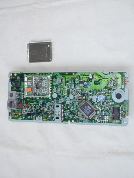
Click to zoom
Application Details
- Equipment Class
- DXT - Part 15 Low Power Transceiver, Rx Verified
- Date of Grant
- Apr 02, 2001
- Application Purpose
- Original Equipment
- Date of Application
- Mar 06, 2001
- Equipment Note
- Cordless Telephone
- Frequency Range
- 902.71290000 - 927.28890000
- Country
- United States
Documents & Files
Document Text
Text extracted from the exhibit documents filed with the FCC. Open a document above to read the original.
Users Manual
900MHz Cordless Answering System Pulse-or-tone dialing capability Model No. KX-TC1743B PLEASE READ BEFORE USE AND SAVE. Charge the battery for about 15 hours before initial use. Contents: Location of Controls . . . . . . . . . . . . . . . . 3 Connections . . . . . . . . . . . . . . . . . . . . . . 6 Battery Charge . . . . . . . . . . . . . . . . . . . 7 Selecting the Dialing Mode . . . . . . . . . . . 8 Recording a Greeting Message . . . . . . . 9 Making/Answering Calls . . . . . . . . . . . . 10 Caller ID Service . . . . . . . . . . . . . . . . . 12 Speed Dialer. . . . . . . . . . . . . . . . . . . . . 12 Automatic Answering Operation . . . . . . 13 Listening to Messages . . . . . . . . . . . . . 13 Important Safety Instructions . . . . . . . . 14 FCC and Other Information. . . . . . . . . . 16 OPERATING INSTRUCTIONS – 2 – Please read IMPORTANT SAFETY INSTRUCTIONS on pages 14–15 before use. Read and understand all instructions. Thank you for purchasing your new Panasonic cordless telephone. Attach your purchase receipt here. For your future reference Serial No. Date of purchase (found on the bottom of the unit) Name and address of dealer – 3 – Location of Controls ∫Handset Charge Contacts Microphone (OFF) Button (Speakerphone) Button (Talk) Button Antenna Display Navigator key ((›), (‹), (fi), EDIT (fl)) (INTERCOM/HOLD/CLEAR) Button (REDIAL/PAUSE/FUNCTION) Button Headset Jack (TONE) Button (FLASH/CALL–WAIT/PLAYBACK) Button Speaker Back side – 4 – ∫Base unit IN USE/CHARGE Indicator Antenna CALLER ID Indicator (TONE) Button (AUTO/PROGRAM) Button (LOCATOR/INTERCOM) Button (HOLD/RINGER) Button (REDIAL/PAUSE) Button (DIGITAL–SP-PHONE) (Speakerphone) Button and Indicator MIC (Microphone) (FLASH/CALL–WAIT) Button Charge Contacts VOLUME (_), (^) Buttons Display – 5 – ∫Base unit (NEW–MESSAGE) Button (STOP) Button (ANSWER–ON) Button and Indicator (ERASE) Button (GREETING) Button (REPEAT) Button (SKIP) Button – 6 – Connections ≥USE ONLY WITH Panasonic AC ADAPTOR KX-TCA1 (Order No. KX-TCA1-G). ≥The AC adaptor must remain connected at all times. (It is normal for the adaptor to feel warm during use.) Telephone Line Cord Single-Line Telephone Jack (RJ11C) Power Outlet (AC 120 V, 60 Hz) AC Adaptor Hook Raise the antenna. Fasten the AC adaptor cord to prevent it from being disconnected. – 7 – Battery Charge To power the handset, charge the battery. Place the handset on the base unit for about 15 hours before initial use. ≥The IN USE/CHARGE indicator lights. ∫Recharge Recharge the battery when: —“Recharge battery” is displayed, —“” flashes on the display, or —the handset beeps intermittently while it is in use. ≥Battery life may be shortened depending on usage conditions, such as viewing the Caller ID Caller List or directory list, and ambient temperature. ≥Clean the handset and base unit charge contacts with a soft, dry cloth once a month. Clean more often if the unit is subject to grease, dust or high humidity.Otherwise the battery may not charge properly. ≥If the battery is fully charged, you do not have to place the handset on the base unit until “Recharge battery” is displayed and/or “” flashes. This will maximize the battery life. ≥The battery cannot be overcharged. Attention: The product you have purchased is powered by a nickel cadmium battery which is recyclable. At the end of its useful life, under various state and local laws, it is illegal to dispose of this battery into your municipal waste stream. Please call 1-800-8-BATTERY for information on how to recycle this battery. – 8 – Selecting the Dialing Mode 1 Press (REDIAL/PAUSE/FUNCTION). 2 Press (›)or (‹)repeatedly until the arrow points to “Program”. 3 Press EDIT(fl)(Yeskey). 4 Press (›)or (‹)repeatedly until the arrow points to “Set dial mode”. 5 Press EDIT(fl)(Yeskey). 6 Press (›)or (‹)to select “Pulse” or “Tone”. Press EDIT(fl)(Savekey). ≥A beep sounds. ≥To return to the standby mode, press (OFF). ≥You can exit the programming mode any time by pressing (OFF). You can program the dialing mode by using the handset near the base unit. If you have touch tone service, set to “Tone”. If rotary or pulse service is used, set to “Pulse”. Your phone comes from the factory set to “Tone”. Make sure the handset and the base unit are in the standby mode. – 9 – Recording a Greeting Message 1 Press (GREETING)until a long beep is heard. 2 Talk clearly, about 8 inches (20 cm) away from the MIC(microphone). 3 When finished, press (STOP). You can record a personal greeting message of up to 2 minutesfor each line or a common greeting message for both lines. If a greeting message is not recorded, one of two pre-recorded greetings will be played when a call is received. ≥All messages (greeting, incoming, etc.) are stored in digital memory. The total recording time is about 15 minutes. We recommend you recorda brief greeting messagein order to leave more time for recording new messages. ∫To check the greeting message(s) Press (GREETING)briefly. ≥The selected greeting(s) is (are) played back. ≥If you do not record a greeting message, one of two messages will be played when a call is received, depending on the caller’s recording time. – 10 – ∫To make a call with the handset 1 Press . 2 Dial a phone number. ≥The dialed number is displayed. ≥After a few seconds, the display will show the length of the call and the battery strength. 3 To hang up, press (OFF)or place the handset on the base unit. ∫To have a hands-free phone conversation with the handset 1 Press . ≥The button lights. 2 Dial a phone number. ≥The dialed number is displayed. ≥After a few seconds, the display will show the length of the call and the battery strength. 3 When the other party answers, talk into the microphone. 4 To hang up, press (OFF)or place the handset on the base unit. ≥The button light goes out. ≥To redial the last number: Press or ¤(REDIAL/PAUSE/FUNCTION). Making/Answering Calls – 11 – ∫To make a call with the base unit 1 Press (DIGITAL\SP-PHONE). ≥The DIGITAL SP-PHONE indicator light…
Text truncated - open the document above for the full version.
Attestation Statements
EXHIBIT E DESCRIPTION OF ELECTRICAL CIRCUITRY BASE UNIT: A) WHEN A BELL SIGNAL ENTERS FROM TEL LINE 1) The bell detection circuit, i.e., the transistor(Q101) begins to operate and its output is inputted to pin 27 of IC201(DSP). 2) To obtain a display synchronized with the bell signal, an IN USE signal is output from pin 70 of IC201(DSP) and INUSE LED(LED202) is lighted up. 3) A portable phone receives a bell from the base station. When the portable phone is switched from the STANDBY to TALK, the base station receives a carrier modulated by data indicating the switch from STANDBY to TALK. The data demodulated at the base station is inputted to pin 57 of IC201, and passes through Q4 to make the circuit relay, then, release the muting and enables talk. B) WHEN A LINE LOOP IS MADE BY A PORTABLE PHONE 1) When the operator of the portable phone switches STANDBY to TALK, the TALK mode data enters the base station and is demodulated at the RF Unit of the base station, and is inputted to pin 66 of IC201. 2) In this time, an IN USE signal is output from pin 70 of IC201, and the IN USE LED (LED202) is lighted up. C) RECIEVER UNIT OPERATION 1) A signal is received by the antenna, and passes through the 902 to 928MHz band pass filter L111, and is inputted to the pin 7 of IC101. 2) The received signal and local signal made by VCO (913.408~916.594MHz) are mixed by IC101 to obtain digitized audio signal. 3) The base band signal is fed to pin 66 of IC201. 4) This audio signal is transmitted to the telephone line by IC201. D) TRANSMISSION UNIT OPERATION 1) An audio signal from the line passes through the interface transistor(Q64). 2) The audio signal is inputted to pin 36 and 44 of IC201. 3) This audio signal is coded by IC201 and output from pin 57 to IC101. 4) This modulated signal goes to the antenna. EXHIBIT E DESCRIPTION OF ELECTRICAL CIRCUITRY PORTABLE UNIT: A) RECEIVER UNIT OPERATION 1) A signal from the base unit is received by the antenna, and passes through the 902 to 928MHz band pass filter L111. And the signal is fed to pin 7 of IC101. 2) An received signal and 1st local signal made by VCO(913.408~916.594MHz) are mixed to obtain digitized audio signal. And this signal goes out from pin 66 of IC101. 3) This digitized audio signal is fed to pin 66 of IC201. 4) This audio signal goes to pin 33 and 34 of IC201, and output to speaker. B) TRANSMISSION UNIT OPERATION 1) When selected TALK switch to TALK, the detect switch of IC201 becomes ON and get into TALK mode. 2) The audio signal from microphone is inputted to pin 46 and 47 of IC201. 3) This audio signal is coded by IC201 and output from pin 57 to IC101. 4) This modulated signal goes to the antenna.
Attestation Statements
EXHIBIT A STATEMENT OF SECURITY CODE This cordless telephone system has 268 million digital security coding combinations that are provided by the following means: • Provided with 28 bits (268 million) for security codes. • When the handset is not on the base unit, the 28 bit codes changes by the free-running timer. • When the user puts the handset on the base unit, the free-running timer ceases and decides the exact security code. The base unit sends the security code information to the handset. • When shipped from the factory, the security code is decided by the manufacture. However, once the user uses the cordless handset, the security code is constantly changing by the free-running timer.
Attestation Statements
To: Katie Hawkins, FCC Application Processing Branch From: Zameel Shahat, Matsushita Electric Corp of America Re: FCC ID ACJ96NKX-TC1743 Applicant: Matsushita Electric Industrial Co Ltd Correspondence Reference Number: 18477 731 Confirmation Number: EA100257 Dear Katie This is in response to your email message regarding Submit occupied bandwidth plots to show compliance with Section 15.249(c) at the band edges. Please be advised Part 15.249(c) did not specify what method of measurement we should use. The test result for spurious emission in our reports are based on measurements employing a CISPR quasi-peak detector, that is why there is no plots, but we have the results in tables. The measurements tables are in page 21 of 25 for the base and page 19 of 23 for handset. Best regards, Zameel Shahat Project Engineer Matsushita Electric Corporation of America Product Safety & Compliance Division (201)392-4161
Cover Letter(s)
March 30, 2001 To: Katie Hawkins, FCC Application Processing Branch From: Zameel Shahat, Matsushita Electric Corp of America Re: FCC ID ACJ96NKX-TC1743 Applicant: Matsushita Electric Industrial Co Ltd Correspondence Reference Number: 731 Confirmation Number: EA100257 Dear Katie This is in response to your email message “ ” 1- As per your request I uploaded A- Internal photograph for base and handset. B- Set-up photographs for base and handset. C- Operational description. 2- You did not send to me any comment or question about Correspondence number 18477. I will consider that you Agree with my answer and you have no outstanding issues About occupied bandwidth plots. Best regards, Zameel Shahat Project Engineer Matsushita Electric Corporation of America Product Safety & Compliance Division (201)392-4161
External Photos
FCC ID: ACJ96NKX-TC1743 FCC ID: ACJ96NKX-TC1743 FCC ID: ACJ96NKX-TC1743 FCC ID: ACJ96NKX-TC1743 FCC ID: ACJ96NKX-TC1743
External Photos
FCC ID: ACJ96NKX-TC1743 FCC ID: ACJ96NKX-TC1743 FCC ID: ACJ96NKX-TC1743 FCC ID: ACJ96NKX-TC1743 FCC ID: ACJ96NKX-TC1743
ID Label/Location Info
EXHIBIT B MARKINGS Base Unit: The base unit provides with the following marking, or equivalent. This device complies with Part 15 of the FCC rules. Operation is subject to the following two conditions: (1) This device may not cause harmful interference, and (2) this device must accept any interference received, including interference that may cause undesired operation. Privacy of communications may not be ensured when using this phone. NOTE: Above markings are shown on bottom of the base unit. Portable Unit: The markings are shown on the bottom side of the portable unit.
Internal Photos
FCC ID: ACJ96NKX-TC1743 FCC ID: ACJ96NKX-TC1743 FCC ID: ACJ96NKX-TC1743
Internal Photos
FCC ID: ACJ96NKX-TC1743 FCC ID: ACJ96NKX-TC1743 FCC ID: ACJ96NKX-TC1743
Test Report
Issue Date : February 28, 2001 Page 1 of 25 EMC EMISSION - TEST REPORT JQA APPLICATION No.: KL80000598 Name of Product: 900MHz Cordless Telephone(Base Unit) Model/Type No.: KX-TC1743 FCC ID: ACJ96NKX-TC1743 Applicant : Kyushu Matsushita Electric Co., Ltd. Address : 1-62, 4-chome, Minoshima, Hakata-ku, Fukuoka 812-8531, Japan Manufacturer : Kyushu Matsushita Electric Co., Ltd. Address : 1-62, 4-chome, Minoshima, Hakata-ku, Fukuoka 812-8531, Japan Receive date of EUT: February 9, 2001 Final Judgement :Passed TEST RESULTS IN THIS REPORT are obtained in use of equipment that is traceable to Electro- technical Lab. of MITI Japan and Communications Research Lab. of PTT Japan. THE TEST RESULTS only responds to the test sample. This test report shall not be reproduced except in full. JAPAN QUALITY ASSURANCE ORGANIZATION (JQA) KITA-KANSAI TESTING CENTER EMC DIVISION Page 2 of 25 DIRECTORY Page A) Documentation Directory2 Test Regulation / General Information3 - 4 Test Conditions5-8 Configuration of EUT / Operation mode of the EUT9 - 10 EUT Modification / Responsible Party / Deviation from Standard11 Test results / Measurement Uncertainty12 Summary13 Test System-Arrangement (Drawings) 14 Preliminary Test and Test-setup (Drawings) 15 - 18 Test-setup (Photographs) at worst case 19 B) Test data Conducted Emission450 kHz - 30 MHz20 Electromagnetic Field Radiated Emission 9 kHz - 10 GHz21 - 25 JQA Application No. : KL80000598Regulation : CFR 47 FCC Rules Part 15 Model No.: KX-TC1743Issue Date : February 28, 2001 FCC ID: ACJ96NKX-TC1743 JQA Application No. : KL80000598Regulation : CFR 47 FCC Rules Part 15 Model No.: KX-TC1743Issue Date : February 28, 2001 FCC ID: ACJ96NKX-TC1743 Page 3 of 25 TEST REGULATION FCC Rules and Regulations Part 15 Subpart A and C (September 20, 2000) ô- Class A Digital Device ô- Class B Digital Device ò- Intentional Radiator(Sec.15.249) ô- Receiver Test items: ô- Sec.15.203 : Antenna requirement ò- Sec.15.205 : Restricted bands of operation ò- Sec.15.207 : Conducted limits ò- Sec.15.209 : Radiated emission limits general requirements ô- Sec.15.214 : Cordless Telephones ò- Sec.15.249 : Operation within the bands 902-928MHz, 2400-2483.5MHz, 5725-5875MHz, and 24.0-24.25GHz Test procedure: Conducted emission and radiated emission test were performed according to the procedures in ANSI C63.4-1992. GENERAL INFORMATION Test facility: 1) Test Facility located at Kita-Kansai : 1st and 2nd Open Sites (3 m Site) Test Facility located at Kameoka Open Site (3, 10 and 30 m, on common plane) FCC filing No. : 31040/SIT 1300F2 2) KITA-KANSAI TESTING CENTER is recognized under the National Voluntary Laboratory Accreditation Program for satisfactory compliance established in Title 15, Part 285 Code of Federal Regulations. NVLAP Lab Code: 200191-0 Definitions for symbols used in this test report: ò- Black box indicates that the listed condition, standard or equipment is applicable for this Report. ô- Blank box indicates that the listed condition, standard or equipment is not applicable for this Report. JQA Application No. : KL80000598Regulation : CFR 47 FCC Rules Part 15 Model No.: KX-TC1743Issue Date : February 28, 2001 FCC ID: ACJ96NKX-TC1743 Page 4 of 25 Description of the Equipment Under Test (EUT): 1) Name: 900MHz Cordless Telephone(Base Unit) 2) Model/Type No.: KX-TC1743 3) Product Type: Pre-Production (S/N: ---) 4) Category: Intentional Radiator 5) EUT Authorization: - Verification- Certification- D.o.C.ôòô 6) Transmitting Frequency: 902.713 MHz(1ch) - 927.289 MHz(109ch) 7) Receiving Frequency: 902.713 MHz(1ch) - 927.289 MHz(109ch) 8) Emission Designations: F1E 9) Type of Antenna: Permanently Dipole Antenna 10) Power Rating: AC 120V 60Hz 1 2-pin plug(AC adaptor : KX-TCA1)φ JQA Application No. : KL80000598Regulation : CFR 47 FCC Rules Part 15 Model No.: KX-TC1743Issue Date : February 28, 2001 FCC ID: ACJ96NKX-TC1743 Page 5 of 25 TEST CONDITIONS AC Powerline Conducted Emission Measurement wasperformedinthefollowingtestsite. Test location: KITA-KANSAI Testing Center 7-7, Ishimaru, 1-Chome, Mino-Shi, Osaka, 562-0027, Japan ò-Shieldedroom KAMEOKA EMC Branch 9-1, Ozaki, Inukanno, Nishibetsuin-Cho, Kameoka-Shi, Kyoto, 621-0126, Japan ô-Shieldedroom ô- On metal plane of open site Used test instruments and sites: Model No.Device IDast Cal. DateCal. Interval L ô-ESCS30A-1 ô-ESH2A-2 ò- ESH 2A - 3December, 20001 Year ò- KNW-407D - 6January, 20011 Year ô- KNW-408D - 11 ô-KNW-242D-7 ô- ESH3-Z5D - 12 ô- KNW-341CD - 13 ô- KNW-408D - 14 ô- KNW-244CD - 77 ô- KNW-408D - 78 ô- ESH2-Z5D - 10 ô- ESH2-Z3D - 17 ô- 65 BNC-50-0-1H - 26 ô- 65 BNC-50-0-1H - 27 ô-CableH-7 ò- CableH - 8January, 20011 Year Environmental conditions: Temperature: 24 °C Humidity: 30 % JQA Application No. : KL80000598Regulation : CFR 47 FCC Rules Part 15 Model No.: KX-TC1743Issue Date : February 28, 2001 FCC ID: ACJ96NKX-TC1743 Page 6 of 25 Magnetic Field Radiated Emission Measurement was performed in the frequency range of 9 kHz - 30 MHz, in the following test site. Test location: KITA-KANSAI Testing Center 7-7, Ishimaru, 1-Chome, Mino-Shi, Osaka, 562-0027, Japan ò- 1st open test site (3 meters) ô- 2nd open test site (3 meters) KAMEOKA EMC Branch 9-1, Ozaki, Inukanno, Nishibetsuin-Cho, Kameoka-Shi, Kyoto, 621-0126, Japan ôôôô-1stopentestsite-3m-10m-30m ôôô-2ndopentestsite-3m-10m Used test instruments: Model No.Device IDast Cal. DateCal. Interval L ô-ESCS30A-1 ô-ESH2A-2 ò- ESH 2A - 3December, 20001 Year ô- HFH2-Z2C - 2 ò- HFH2-Z2C - 3July, 20001 Year Environmental conditions: Temperature: 15 °C Humidity: 32 % JQA Application No. : KL80000598Regulation : CFR 47 FCC Rules Part 15 Model No.: KX-TC1743Issue Date : February 28, 2001 FCC ID: ACJ96NKX-TC1743 Page 7 of 25 Electromagnetic Field Radiated Emission Measurement was performed in horizontal and vertical polarization, in the frequency range of 30 MHz - 1000 MHz, in the following test site. Test location: KITA-KANSAI Testing Center 7-7, Ishimaru, 1-Chome, Mino-Shi, Osaka, 562-0027, Japan ò-…
Text truncated - open the document above for the full version.
Test Report
Issue Date : February 28, 2001 Page 1 of 23 EMC EMISSION - TEST REPORT JQA APPLICATION No.: KL80000599 Name of Product: 900MHz Cordless Telephone(Handset) Model/Type No.: KX-TC1743 FCC ID: ACJ96NKX-TC1743 Applicant : Kyushu Matsushita Electric Co., Ltd. Address : 1-62, 4-chome, Minoshima, Hakata-ku, Fukuoka 812-8531, Japan Manufacturer : Kyushu Matsushita Electric Co., Ltd. Address : 1-62, 4-chome, Minoshima, Hakata-ku, Fukuoka 812-8531, Japan Receive date of EUT: February 9, 2001 Final Judgement :Passed TEST RESULTS IN THIS REPORT are obtained in use of equipment that is traceable to Electro- technical Lab. of MITI Japan and Communications Research Lab. of PTT Japan. THE TEST RESULTS only responds to the test sample. This test report shall not be reproduced except in full. JAPAN QUALITY ASSURANCE ORGANIZATION (JQA) KITA-KANSAI TESTING CENTER EMC DIVISION Page 2 of 23 DIRECTORY Page A) Documentation Directory2 Test Regulation / General Information3 - 4 Test Conditions5-8 Configuration of EUT / Operation mode of the EUT9 - 10 EUT Modification / Responsible Party / Deviation from Standard11 Test results / Measurement Uncertainty12 Summary13 Test System-Arrangement (Drawings) 14 Preliminary Test and Test-setup (Drawings) 15 - 17 Test-setup (Photographs) at worst case 18 B) Test data Conducted Emission450 kHz - 30 MHzN/A Electromagnetic Field Radiated Emission 9 kHz - 10 GHz19 - 23 JQA Application No. : KL80000599Regulation : CFR 47 FCC Rules Part 15 Model No.: KX-TC1743Issue Date : February 28, 2001 FCC ID: ACJ96NKX-TC1743 JQA Application No. : KL80000599Regulation : CFR 47 FCC Rules Part 15 Model No.: KX-TC1743Issue Date : February 28, 2001 FCC ID: ACJ96NKX-TC1743 Page 3 of 23 TEST REGULATION FCC Rules and Regulations Part 15 Subpart A and C (September 20, 2000) ô- Class A Digital Device ô- Class B Digital Device ò- Intentional Radiator(Sec.15.249) ô- Receiver Test items: ô- Sec.15.203 : Antenna requirement ò- Sec.15.205 : Restricted bands of operation ô- Sec.15.207 : Conducted limits ò- Sec.15.209 : Radiated emission limits general requirements ô- Sec.15.214 : Cordless Telephones ò- Sec.15.249 : Operation within the bands 902-928MHz, 2400-2483.5MHz, 5725-5875MHz, and 24.0-24.25GHz Test procedure: Radiated emission test was performed according to the procedures in ANSI C63.4-1992. GENERAL INFORMATION Test facility: 1) Test Facility located at Kita-Kansai : 1st and 2nd Open Sites (3 m Site) Test Facility located at Kameoka Open Site (3, 10 and 30 m, on common plane) FCC filing No. : 31040/SIT 1300F2 2) KITA-KANSAI TESTING CENTER is recognized under the National Voluntary Laboratory Accreditation Program for satisfactory compliance established in Title 15, Part 285 Code of Federal Regulations. NVLAP Lab Code: 200191-0 Definitions for symbols used in this test report: ò- Black box indicates that the listed condition, standard or equipment is applicable for this Report. ô- Blank box indicates that the listed condition, standard or equipment is not applicable for this Report. JQA Application No. : KL80000599Regulation : CFR 47 FCC Rules Part 15 Model No.: KX-TC1743Issue Date : February 28, 2001 FCC ID: ACJ96NKX-TC1743 Page 4 of 23 Description of the Equipment Under Test (EUT): 1) Name: 900MHz Cordless Telephone(Handset) 2) Model/Type No.: KX-TC1743 3) Product Type: Pre-Production (S/N: ---) 4) Category: Intentional Radiator 5) EUT Authorization: - Verification- Certification- D.o.C.ôòô 6) Transmitting Frequency: 902.713 MHz(1ch) - 927.289 MHz(109ch) 7) Receiving Frequency: 902.713 MHz(1ch) - 927.289 MHz(109ch) 8) Emission Designations: F1E 9) Type of Antenna: Permanently Monopole Antenna 10) Power Rating: DC 3.6V(Ni-Cd Battery Pack : PQP85AA3A) JQA Application No. : KL80000599Regulation : CFR 47 FCC Rules Part 15 Model No.: KX-TC1743Issue Date : February 28, 2001 FCC ID: ACJ96NKX-TC1743 Page 5 of 23 TEST CONDITIONS AC Powerline Conducted Emission Measurement wasperformedinthefollowingtestsite. Test location: KITA-KANSAI Testing Center 7-7, Ishimaru, 1-Chome, Mino-Shi, Osaka, 562-0027, Japan ô-Shieldedroom KAMEOKA EMC Branch 9-1, Ozaki, Inukanno, Nishibetsuin-Cho, Kameoka-Shi, Kyoto, 621-0126, Japan ô-Shieldedroom ô- On metal plane of open site Used test instruments and sites: Model No.Device IDast Cal. DateCal. Interval L ô-ESCS30A-1 ô-ESH2A-2 ô-ESH2A-3 ô-KNW-407D-6 ô- KNW-408D - 11 ô-KNW-242D-7 ô- ESH3-Z5D - 12 ô- KNW-341CD - 13 ô- KNW-408D - 14 ô- KNW-244CD - 77 ô- KNW-408D - 78 ô- ESH2-Z5D - 10 ô- ESH2-Z3D - 17 ô- 65 BNC-50-0-1H - 26 ô- 65 BNC-50-0-1H - 27 ô-CableH-7 ô-CableH-8 Environmental conditions: Temperature:°C Humidity:% JQA Application No. : KL80000599Regulation : CFR 47 FCC Rules Part 15 Model No.: KX-TC1743Issue Date : February 28, 2001 FCC ID: ACJ96NKX-TC1743 Page 6 of 23 Magnetic Field Radiated Emission Measurement was performed in the frequency range of 9 kHz - 30 MHz, in the following test site. Test location: KITA-KANSAI Testing Center 7-7, Ishimaru, 1-Chome, Mino-Shi, Osaka, 562-0027, Japan ô- 1st open test site (3 meters) ò- 2nd open test site (3 meters) KAMEOKA EMC Branch 9-1, Ozaki, Inukanno, Nishibetsuin-Cho, Kameoka-Shi, Kyoto, 621-0126, Japan ôôôô-1stopentestsite-3m-10m-30m ôôô-2ndopentestsite-3m-10m Used test instruments: Model No.Device IDast Cal. DateCal. Interval L ô-ESCS30A-1 ô-ESH2A-2 ò- ESH 2A - 3December, 20001 Year ô- HFH2-Z2C - 2 ò- HFH2-Z2C - 3July, 20001 Year Environmental conditions: Temperature: 19 °C Humidity: 30 % JQA Application No. : KL80000599Regulation : CFR 47 FCC Rules Part 15 Model No.: KX-TC1743Issue Date : February 28, 2001 FCC ID: ACJ96NKX-TC1743 Page 7 of 23 Electromagnetic Field Radiated Emission Measurement was performed in horizontal and vertical polarization, in the frequency range of 30 MHz - 1000 MHz, in the following test site. Test location: KITA-KANSAI Testing Center 7-7, Ishimaru, 1-Chome, Mino-Shi, Osaka, 562-0027, Japan ô- 1st open test site (3 meters) ò- 2nd open test site (3 meters) KAMEOKA EMC Branch 9-1, Ozaki, Inukanno, Nishi…
Text truncated - open the document above for the full version.
Test Setup Photos
JQA Application No. : KL80000598Regulation : CFR 47 FCC Rules Part 15 Model No.: KX-TC1743Issue Date : February 28, 2001 FCC ID: ACJ96NKX-TC1743 Page 19 of 25 Test-Setup (Photographs) at worst case Conducted Emission 450kHz - 30MHz:Radiated Emission 9 kHz - 10 GHz Front ViewHorizontal polarization Side ViewVertical polarization
Test Setup Photos
JQA Application No. : KL80000599Regulation : CFR 47 FCC Rules Part 15 Model No.: KX-TC1743Issue Date : February 28, 2001 FCC ID: ACJ96NKX-TC1743 Page 18 of 23 Test-Setup (Photographs) at worst case Conducted Emission 450kHz - 30MHz:Radiated Emission 9 kHz - 10 GHz Not Applicable Horizontal polarization Vertical polarization
Contact Information
Applicant
Ben Botros(Project Manager)
Test Firm
Japan Quality Assurance Org.Katsumi Nishii
Technical Specifications
| # | Rule Parts | Frequency Range | Power Output |
|---|---|---|---|
| 1 | 15C | 902.7129 MHz - 927.2889 MHz | - |
Other Applications from Panasonic Corporation of North America
ACJ-EAH-A1000
Aug 19, 2026Digital Wireless Stereo Headphones
Equipment Class
DSS - Part 15 Spread Spectrum TransmitterACJ9TGFZVNF3G1
Jun 16, 2026Contactless Smart Card Reader
Equipment Class
DXX - Part 15 Low Power Communication Device Transmitter
ACJ932AM2301
Jan 29, 2025Car AV Control Unit for CDC
Equipment Class
DTS - Digital Transmission SystemACJ96NKX-TGEA60B
Aug 13, 2024DECT Handset
Equipment Class
PUE - Part 15 Unlicensed PCS portable Tx held to earACJ96NKX-TGE630B
Aug 12, 2024DECT Base Unit
Equipment Class
PUB - Part 15 Unlicensed PCS Base Station