ACJ96NKX-TD78962.4 GHz WIRELESS PROPRIETARY CORDLESS TELEPHONE
Panasonic Corporation of North America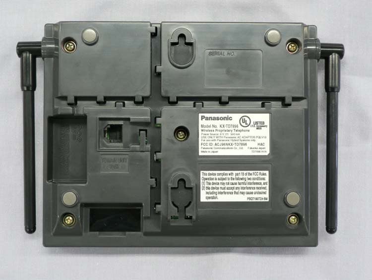
Click to zoom
Application Details
- Equipment Class
- DSS - Part 15 Spread Spectrum Transmitter
- Date of Grant
- Jun 16, 2005
- Application Purpose
- Original Equipment
- Date of Application
- Jun 16, 2005
- Equipment Note
- 2.4 GHz WIRELESS PROPRIETARY CORDLESS TELEPHONE
- Frequency Range
- 2401.05600000 - 2479.68000000
- Country
- United States
Documents & Files
Document Text
Text extracted from the exhibit documents filed with the FCC. Open a document above to read the original.
Users Manual
FCC ID : ACJ96NKX-TD7896 1 of 1 STATEMENT OF SECURITY CODE This wireless system has 1000 billion digital security coding combinations that are provided by the following means: • Provided with 40 bits (1000 billion) for security codes. • When shipped from the factory, the security code is decided by the manufacturer.
Users Manual
Wireless Proprietary Telephone Operating Instructions Model No. KX-TD7896 Thank you for purchasing the Panasonic KX-TD7896 Wireless PT (Wireless Proprietary Telephone). Please read this manual carefully before using this product and save this manual for future use. This manual is designed to be used with the KX-TD7896 Wireless PT and a Panasonic KX-TA/KX-TAW/KX-TD/KX-TDA series PBXs (Business Telephone Systems). This product is compatible with (Setting the PBX Type → See page 38.): • KX-TA624/KX-TA824/KX-TAW848/KX-TDA series (KX-TDA50/KX-TDA100/KX-TDA200) - PBX Type 1 • KX-TA308/KX-TA1232/KX-TD series (KX-TD308/KX-TD500/KX-TD816/KX-TD1232) - PBX Type 2 Please use only Panasonic battery and charge the battery for about 7 hours before initial use. Selecting the Display Language → See page 11. 7 3 6 2 4 8 9 5 0 1 H O LD X F E R RCL FLASH CLR 2 Please read “Important Information” on page 40 before use. Read and understand all instructions. Accessories AC adaptor (PQLV19) Tw o Charger* 1 One Battery (N4HHGMB00005 or HHR-P103) One Handset Clip* 2 One Belt Holder* 3 One Battery Cover One • In this manual, the suffix of each model number is omitted. • To order accessories, call toll free 1-800-332-5368. * 1 Charger: For KX-TD7896 (Black Model) users: Part no. PSLP1321ZA For KX-TD7896-W (White Model) users: Part no. PSLP1321ZA-W * 2 Handset Clip: For KX-TD7896 (Black Model) users: Part no. PSKE1084ZA4-H270 For KX-TD7896-W (White Model) users: Part no. PSKE1084ZA3-W140 * 3 Belt Holder: For KX-TD7896 (Black Model) users: Part no. PSKE1040ZA For KX-TD7896-W (White Model) users: Part no. PSKE1040ZA2-W140 Table of Contents 3 For Best Performance.................................................................................... 4 Before Operating the Handset ...................................................................... 5 Location of Controls .................................................................................... 5 Connection .................................................................................................. 7 Battery Installation....................................................................................... 7 Battery Charge ............................................................................................ 8 Handset Clip and Belt Holder...................................................................... 8 Wall Mounting ............................................................................................. 9 Power On/Off ............................................................................................ 11 Selecting the Display Language................................................................ 11 Display Icons............................................................................................. 12 Operation Outline ...................................................................................... 13 Function Menu Display.............................................................................. 14 PBX Feature Keys..................................................................................... 15 PBX Flexible Key Display.......................................................................... 16 Soft Key Display........................................................................................ 17 Ringer Volume Adjustment ....................................................................... 18 Receiver/Speaker/Headset Volume Adjustment ....................................... 18 While Receiving Calls .................................................................................. 19 Ringer Volume Adjustment ....................................................................... 19 Using the Phonebook .................................................................................. 20 Handset Phonebook.................................................................................. 20 Storing an item in the Handset Phonebook............................................... 22 Using Hot Key Dial .................................................................................... 22 Entering Characters .................................................................................. 23 Feature List .................................................................................................. 25 Programming ................................................................................................ 32 Changing the Initial Settings ..................................................................... 32 Setting Base Unit ...................................................................................... 39 Important Information .................................................................................. 40 For Best Performance 4 For Best Performance Noise Calls are transmitted between the base unit and the handset using radio waves. For maximum distance and noise free operation, the recommended base unit location is: • The 2.4 GHz wireless telephone cannot be used together. • If you are out of range, an alarm tone sounds continuously. Operating Distance When using more than 2 base units, the distance between one unit and the others must be at least 3 m (10 ft), or else proper radio transmission cannot be obtained. Raise the antennas. Away from electrical appliances such as a fax, radio, personal computer, or microwave. In a HIGH location, with no obstructions or interference from electrical appliances. Before Operating the Handset 5 Before Operating the Handset Location of Controls Handset 7 1 0 3 6 2 4 8 9 5 Receiver Display TALK/SP-PHONE HOLD Charge Contact Right Soft Key CANCEL/POWER Charge Contact TRANSFER/CLEAR Joystick INTERCOM Ringing/Charge Indicator Headset Jack RECALL/FLASH Microphone Back View Speaker – The headset is an option. Please use only the Panasonic KX-TCA86/KX- TCA88HA/KX-TCA91/KX- TCA92 headset. Open the cover. Left Soft Key (Speakerphone) Before Operating the Handse…
Text truncated - open the document above for the full version.
Cover Letter(s)
June 9, 2005 TIMCO ENGINEERING INC. P.O. Box 370 849 N.W. State Road 45 Newberry, Florida Subject: FCC Certification Authorization Application under FCC Part 15, Subpart C, Sec. 15.247 – Frequency Hopping Spread Spectrum (FHSS) Transmitters Operating in the 2400 – 2483.5 MHz Band Applicant: Panasonic Corporation of North America Product: 2.4 GHz Wireless Proprietary Telephone Model No.: KX-TD7896 FCC ID: ACJ96NKX-TD7896 Dear Sir/Madam, As appointed agent for Panasonic Corporation of North America, we would like to submit the application to Timco Engineering Inc. for equipment authorization of the above product. Please review all files uploaded to TIMCO Upload Web Site. The 2.4 GHz Wireless Proprietary Telephone is a cordless telephone system, which consists of both base and handset units. The transceiver portion of this product incorporates a frequency hopping spread spectrum transmitter with GFSK modulation operating within 2401.056 – 2479.680 MHz frequency range.The base unit uses two permanently attached ½ wave dipole antennas with 2.14 dBi nominal antenna gain. The handset uses one permanently attached ¼ wave helical antennas with 2.14 dBi. If you have any queries, please do not hesitate to contact us. Yours truly, Tri Minh Luu, P. Eng., V.P., Engineering TML/AD Encl 3000 Bristol Circle, Oakville, Ontario, Canada L6H 6G4 Tel.: (905) 829-1570 Fax.: (905) 829-8050 Website: www.ultratech-labs.com Email: [email protected] UltraTech Group of Labs 31040/SIT C-1376 46390-2049 200093-0 2 00-034 SL2-IN-E-1119R
External Photos
Panasonic Communications Co., Ltd. FCC ID: ACJ96NKX-TD7896 External Photos General view of system 1 of 5 Panasonic Communications Co., Ltd. FCC ID: ACJ96NKX-TD7896 General view of base unit Rear view of base unit 2 of 5 Panasonic Communications Co., Ltd. FCC ID: ACJ96NKX-TD7896 General view of handset Front view of handset 3 of 5 Panasonic Communications Co., Ltd. FCC ID: ACJ96NKX-TD7896 Rear view of handset Rear view of handset (battery cover & battery removed) 4 of 5 Panasonic Communications Co., Ltd. FCC ID: ACJ96NKX-TD7896 Rear view of battery charger 5 of 5
ID Label/Location Info
FCC ID: ACJ96NKX-TD7896 ID Label / Location Info. for KX-TD7896 1) Base Unit 1 of 2 FCC ID: ACJ96NKX-TD7896 2) Handset 2 of 2
Internal Photos
Panasonic Communications Co., Ltd. FCC ID: ACJ96NKX-TD7896 Internal Photos Internal view of base unit Opposite side of base unit PCB 1 of 3 Panasonic Communications Co., Ltd. FCC ID: ACJ96NKX-TD7896 Internal view of handset Opposite side of handset PCB 2 of 3 Panasonic Communications Co., Ltd. FCC ID: ACJ96NKX-TD7896 RF module for both base unit and handset (mount inside the shield case) Internal view of battery charger 3 of 3
RF Exposure Info
Wireless Proprietary Telephone Model No.: KX-TD7896 Tested For Panasonic Corporation of North America One Panasonic Way, 4B-8 Secaucus, New Jersey UsA 07094 In Accordance With SAR (Specific Absorption Rate) Requirements using guidelines established in IEEE C95.1-1991, FCC OET Bulletin 65 (Supplement C), Industry Canada RSS-102(Issue 1) and ACA Radiocommunications (Electromagnetic Radiation – Human Exposure) Amendment Standard 2000 (No. 1) UltraTech's File No.: PAN-061-SAR This Test report is Issued under the Authority of Tri M. Luu, Professional Engineer, Vice President of Engineering UltraTech Group of Labs Date: April 18, 2005 Report Prepared by: JaeWook Choi, SAR System Engineer Tested by: Carolyn Luu Issued Date: April 18, 2005 Test Dates: April 04, 2005 ~ April 05, 2005 The results in this Test Report apply only to the sample(s) tested, which has been randomly selected. UltraTech 3000 Bristol Circle, Oakville, Ontario, Canada, L6H 6G4 Telephone (905) 829-1570 Facsimile (905) 829-8050 Website: www.ultratech-labs.com Email: [email protected] SPECIFIC ABSORPTION RATE (SAR) Page 1 IEEE C95.1-1991, FCC OET Bulletin 65 (Supplement C), Industry Canada RSS-102(Issue 1) and ACA Radiocommunications (Electromagnetic Radiation – Human Exposure) Amendment Standard 2000 (No. 1) Wireless Proprietary Telephone M/N: KX-TD7896 FCC ID: ACJ96NKX-TD7896 ULTRATECH GROUP OF LABS File #: PAN-061-SAR 3000 Bristol Circle, Oakville, Ontario, Canada L6H 6G4 April 18, 2005 Tel. #: 905-829-1570, Fax. #: 905-829-8050, Email: [email protected], Website: http://www.ultratech-labs.com • Assessed by ITI (UK) Competent Body, NVLAP (USA) Accreditation Body & ACA/AUSTEL (Australia), VCCI (Japan) • Accredited by Industry Canada (Canada) under ACC-LAB (Europe/Canada MRA and APEC/Canada MRA) • Recognized/Listed by FCC (USA ) • All test results contained in this engineering test report are traceable to National Institute of Standards and Technology (NIST) TABLE OF CONTENTS EXHIBIT 1. INTRODUCTION ................................................................................................................................................ 5 1.1. SCOPE ............................................................................................................................................................................... 5 1.2. REFERENCES................................................................................................................................................................... 5 EXHIBIT 2. PERFORMANCE ASSESSMENT ..................................................................................................................... 6 2.1. CLIENT AND MANUFACTURER INFORMATION ...................................................................................................... 6 2.2. DEVICE UNDER TEST (D.U.T.) DESCRIPTION.............................................................................................................. 6 2.3. LIST OF D.U.T.’S ACCESSORIES:.................................................................................................................................. 7 2.4. SPECIAL CHANGES ON THE D.U.T.’S HARDWARE/SOFTWARE FOR TESTING PURPOSES ............................. 7 2.5. ANCILLARY EQUIPMENT ............................................................................................................................................. 7 2.6. GENERAL TEST CONFIGURATIONS ........................................................................................................................... 7 2.6.1. Equipment Configuration ........................................................................................................................................... 7 2.6.2. Exercising Equipment................................................................................................................................................. 7 2.7. SPECIFIC OPERATING CONDITIONS...................................................................................................................................... 7 2.8. BLOCK DIAGRAM OF TEST SETUP ............................................................................................................................. 8 EXHIBIT 3. SUMMARY OF TEST RESULTS ...................................................................................................................... 9 3.1. LOCATION OF TESTS ..................................................................................................................................................... 9 3.2. APPLICABILITY & SUMMARY OF SAR RESULTS..................................................................................................... 9 EXHIBIT 4. MEASUREMENTS, EXAMINATIONS & TEST DATA .............................................................................. 10 4.1. TEST SETUP ................................................................................................................................................................... 10 4.2. PHOTOGRAPH OF D.U.T. AND ALL ACCESORIES................................................................................................................ 11 4.3. PHOTOGRAPHS OF D.U.T. POSITION ........................................................................................................................16 4.3.1. Head Configuration.................................................................................................................................................. 16 4.3.1.1. Right head – Cheek position .................................................................................................................................................... 16 4.3.1.2. Right head – Tilt position ........................................................................................................................................................ 17 4.3.1.3. Left head – Cheek position ...................................…
Text truncated - open the document above for the full version.
RF Exposure Info
April 18, 2005 File No.: PAN-061-SAR Panasonic Corporation of North America One Panasonic Way, 4B-8 Secaucus, New Jersey, USA 07094 NOT TRANSFERABLE This Verification Certificate is hereby issued to the named GRANTEE and is VALID ONLY for the equipment identified hereon for use under the rules and regulations listed below: GRANTEE'S NAME: Panasonic Corporation of North America PRODUCT UNDER TEST: Wireless Proprietary Telephone MODEL NO.: KX-TD7896 FCC ID: ACJ96NKX-TD7896 OPERATING FREQUENCY RANGE: 2401.056 ~ 2479.680 MHz MEASURED RF OUTPUT POWER: 24.47 dBm peak DEVICE CATEGORY: Portable EXPOSURE CATEGORY: General Population/Uncontrolled MAX. PEAK SPATIAL-AVERAGE SAR 1g : 0.15 W/Kg This wireless portable device has been shown to be compliant for Specific Absorption Rate (SAR) for General Population/Uncontrolled exposure limit. APPLICABLE STANDARDS: SAR (Specific Absorption Rate) requirements using guidelines established in IEEE C95.1-1991, FCC OET Bulletin 65 (Supplement C Edition 01-01), Industry Canada RSS-102(Issue 1) and ACA Radiocommunications (Electromagnetic Radiation – Human Exposure) Amendment Standard 2000 (No. 1) Approved by: Tri M. Luu, P.Eng. V.P. – Engineering UltraTech 3000 Bristol Circle, Oakville, Ontario, Canada, L6H 6G4 Tel.: (905) 829-1570 Fax.: (905) 829-8050 Website: www.ultratech-labs.com Email: [email protected], Email: [email protected] 2 31040/SIT C-1376 46390-2049 200093-0 SL2-IN-E-1119R 00-034
Test Report
ENGINEERING TEST REPORT Wireless Proprietary Telephone Model No.: KX-TD7896 FCC ID: ACJ96NKX-TD7896 Applicant: Panasonic Corporation of North America One Panasonic Wa, 4B-8 Secaucus, New Jersey USA, 07094 In Accordance With Federal Communications Commission (FCC) Part 15, Subpart C, Section 15.247 Frequency Hopping Spread Spectrum (FHSS) Operating in the Frequency Band 2400 – 2483.5 MHz UltraTech's File No.: PAN-061F15C247 This Test report is Issued under the Authority of Tri M. Luu, Professional Engineer, Vice President of Engineering UltraTech Group of Labs Date: April 19, 2005 Report Prepared by: Anca Dobre Issued Date: April 19, 2005 Tested by: Hung Trinh, RFI Technician Test Dates: March 21-22, 2005; April 11-15, 2005 The results in this Test Report apply only to the sample(s) tested, and the sample tested is randomly selected. This report must not be used by the client to claim product endorsement by NVLAP or any agency of the US Government. UltraTech 3000 Bristol Circle, Oakville, Ontario, Canada, L6H 6G4 Tel.: (905) 829-1570 Fax.: (905) 829-8050 Website: www.ultratech-labs.com , Email: [email protected], Email: [email protected] 2 31040/SIT C-1376 46390-2049 200093-0 SL2-IN-E-1119R 00-034 FCC Part 15, Subpart C, Section 15.247 – Frequency Hopping Transmitters Page 1 Wireless Proprietary Telephone, Model KX-TD7896 FCC ID: ACJ96NKX-TD7896 ULTRATECH GROUP OF LABS File #: PAN-061F15C247 3000 Bristol Circle, Oakville, Ontario, Canada L6H 6G4 April 19, 2005 Tel. #: 905-829-1570, Fax. #: 905-829-8050, Email: [email protected], Website: http://www.ultratech-labs.com All test results contained in this engineering test report are traceable to National Institute of Standards and Technology (NIST) TABLE OF CONTENTS EXHIBIT 1. SUBMITTAL CHECK LIST........................................................................................................................ 2 EXHIBIT 2. INTRODUCTION ......................................................................................................................................... 3 2.1. SCOPE......................................................................................................................................................................... 3 2.2. RELATED SUBMITTAL(S)/GRANT(S)................................................................................................................... 3 2.3. NORMATIVE REFERENCES ................................................................................................................................... 3 EXHIBIT 3. PERFORMANCE ASSESSMENT .............................................................................................................. 4 3.1. CLIENT INFORMATION .......................................................................................................................................... 4 3.2. EQUIPMENT UNDER TEST (EUT) INFORMATION ............................................................................................. 4 3.3. EUT’S TECHNICAL SPECIFICATIONS ..................................................................................................................5 3.4. LIST OF EUT’S PORTS ............................................................................................................................................. 6 3.5. ANCILLARY EQUIPMENT ...................................................................................................................................... 6 EXHIBIT 4. EUT OPERATING CONDITIONS AND CONFIGURATIONS DURING TESTS ............................... 7 4.1. CLIMATE TEST CONDITIONS ................................................................................................................................ 7 4.2. OPERATIONAL TEST CONDITIONS & ARRANGEMENT FOR TESTS ............................................................. 7 EXHIBIT 5. SUMMARY OF TEST RESULTS ............................................................................................................... 8 5.1. LOCATION OF TESTS .............................................................................................................................................. 8 5.2. APPLICABILITY & SUMMARY OF EMC EMISSION TEST RESULTS ............................................................... 8 5.3. MODIFICATIONS INCORPORATED IN THE EUT FOR COMPLIANCE PURPOSES ........................................ 8 EXHIBIT 6. MEASUREMENTS, EXAMINATIONS & TEST DATA FOR EMC EMISSIONS............................... 9 6.1. TEST PROCEDURES................................................................................................................................................. 9 6.2. MEASUREMENT UNCERTAINTIES ...................................................................................................................... 9 6.3. MEASUREMENT EQUIPMENT USED.................................................................................................................... 9 6.4. ESSENTIAL/PRIMARY FUNCTIONS AS DECLARED BY THE MANUFACTURER ......................................... 9 6.5. COMPLIANCE WITH FCC PART 15 – GENERAL TECHNICAL REQUIREMENTS ......................................... 10 6.6. AC POWER LINE CONDUCTED EMISSIONS [§ 15.107 (a)] ............................................................................... 12 6.7. PROVISIONS FOR FREQUENCY HOPPING SYSTEMS [§ 15.247 (a) (1)] ......................................................... 18 6.8. PEAK OUTPUT POWER & EQUIVALENT ISOTROPIC RADIATED POWER (EIRP) [§ 15.247(b)] .............. 50 6.9. RF EXPOSURE REQUIREMENTS [§ 15.247 (h) (i)].............................................................................................. 52 6.10. TRANSMITTER BAND-EDGE & SPURIOUS CONDUCTED EMISSIONS [§ 15.247(d)] .................................. 55 6.11. TRANSMITTER BAND-EDGE & SPURIOUS RADIATED EMISSIONS AT 3 METERS [§§15.247 (d), 15.209 & 15.205] ................................................…
Text truncated - open the document above for the full version.
Test Setup Photos
TEST SETUP PHOTOS Panasonic Corporation of North America 2.4 GHz Wireless Proprietary Telephone, Model KX-TD7896 FCC ID: ACJ96NKX-TD7896 A1 - 1 AC Power Line Conducted Emissions (Base Unit - Front View) TEST SETUP PHOTOS Panasonic Corporation of North America 2.4 GHz Wireless Proprietary Telephone, Model KX-TD7896 FCC ID: ACJ96NKX-TD7896 A1 - 2 AC Power Line Conducted Emissions (Base Unit - Side View) TEST SETUP PHOTOS Panasonic Corporation of North America 2.4 GHz Wireless Proprietary Telephone, Model KX-TD7896 FCC ID: ACJ96NKX-TD7896 A1 - 3 AC Power Line Conducted Emissions (Handset - Front View) TEST SETUP PHOTOS Panasonic Corporation of North America 2.4 GHz Wireless Proprietary Telephone, Model KX-TD7896 FCC ID: ACJ96NKX-TD7896 A1 - 4 AC Power Line Conducted Emissions (Handset - Side View) TEST SETUP PHOTOS Panasonic Corporation of North America 2.4 GHz Wireless Proprietary Telephone, Model KX-TD7896 FCC ID: ACJ96NKX-TD7896 A1 - 5 Transmitter/Receiver Radiated Emissions at 3 Meters Base Unit (Antenna perpendicular to ground plane) TEST SETUP PHOTOS Panasonic Corporation of North America 2.4 GHz Wireless Proprietary Telephone, Model KX-TD7896 FCC ID: ACJ96NKX-TD7896 A1 - 6 Transmitter/Receiver Radiated Emissions at 3 Meters Base Unit (Antenna perpendicular to ground plane) TEST SETUP PHOTOS Panasonic Corporation of North America 2.4 GHz Wireless Proprietary Telephone, Model KX-TD7896 FCC ID: ACJ96NKX-TD7896 A1 - 7 Transmitter/Receiver Radiated Emissions at 3 Meters Base Unit (Antenna parallel to ground plane) TEST SETUP PHOTOS Panasonic Corporation of North America 2.4 GHz Wireless Proprietary Telephone, Model KX-TD7896 FCC ID: ACJ96NKX-TD7896 A1 - 8 Transmitter/Receiver Radiated Emissions at 3 Meters Base Unit (Antenna parallel to ground plane) TEST SETUP PHOTOS Panasonic Corporation of North America 2.4 GHz Wireless Proprietary Telephone, Model KX-TD7896 FCC ID: ACJ96NKX-TD7896 A1 - 9 Transmitter/Receiver Radiated Emissions at 3 Meters Handset (Orthogonal Position # 1) TEST SETUP PHOTOS Panasonic Corporation of North America 2.4 GHz Wireless Proprietary Telephone, Model KX-TD7896 FCC ID: ACJ96NKX-TD7896 A1 - 10 Transmitter/Receiver Radiated Emissions at 3 Meters Handset (Orthogonal Position # 1) TEST SETUP PHOTOS Panasonic Corporation of North America 2.4 GHz Wireless Proprietary Telephone, Model KX-TD7896 FCC ID: ACJ96NKX-TD7896 A1 - 11 Transmitter/Receiver Radiated Emissions at 3 Meters Handset (Orthogonal position # 2) TEST SETUP PHOTOS Panasonic Corporation of North America 2.4 GHz Wireless Proprietary Telephone, Model KX-TD7896 FCC ID: ACJ96NKX-TD7896 A1 - 12 Transmitter/Receiver Radiated Emissions at 3 Meters Handset (Orthogonal position # 2) TEST SETUP PHOTOS Panasonic Corporation of North America 2.4 GHz Wireless Proprietary Telephone, Model KX-TD7896 FCC ID: ACJ96NKX-TD7896 A1 - 13 Transmitter/Receiver Radiated Emissions at 3 Meters Handset (Orthogonal position # 3) TEST SETUP PHOTOS Panasonic Corporation of North America 2.4 GHz Wireless Proprietary Telephone, Model KX-TD7896 FCC ID: ACJ96NKX-TD7896 A1 - 14 Transmitter/Receiver Radiated Emissions at 3 Meters Handset (Orthogonal position # 3)
Contact Information
Applicant
Ben Botros(Manager - Regulatory & Compliance)
Test Firm
UltraTech Engineering Labs Inc.Tri Luu
Technical Specifications
| # | Rule Parts | Frequency Range | Power Output |
|---|---|---|---|
| 2 | 15C | 2.40 GHz - 2.48 GHz | 250.00 mW |
Other Applications from Panasonic Corporation of North America
ACJ-EAH-A1000
Aug 19, 2026Digital Wireless Stereo Headphones
Equipment Class
DSS - Part 15 Spread Spectrum TransmitterACJ9TGFZVNF3G1
Jun 16, 2026Contactless Smart Card Reader
Equipment Class
DXX - Part 15 Low Power Communication Device Transmitter
ACJ932AM2301
Jan 29, 2025Car AV Control Unit for CDC
Equipment Class
DTS - Digital Transmission SystemACJ96NKX-TGEA60B
Aug 13, 2024DECT Handset
Equipment Class
PUE - Part 15 Unlicensed PCS portable Tx held to earACJ96NKX-TGE630B
Aug 12, 2024DECT Base Unit
Equipment Class
PUB - Part 15 Unlicensed PCS Base Station