ACJ96NKX-TGCA35AUPCS Cordless Handset
Panasonic Corporation of North America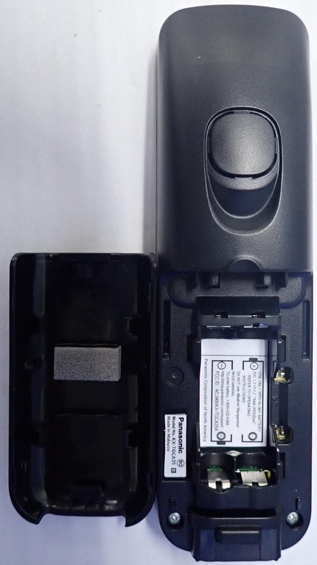
Click to zoom
Application Details
- Equipment Class
- JAB - Part 15 Class B Digital Device
- Date of Grant
- Mar 01, 2022
- Application Purpose
- Original Equipment
- Date of Application
- Mar 01, 2022
- Equipment Note
- UPCS Cordless Handset
- Country
- United States
Documents & Files
Document Text
Text extracted from the exhibit documents filed with the FCC. Open a document above to read the original.
Users Manual
Operating Instructions Cordless Telephone Model No. KX-TGC350 KX-TGC352 Cordless Telephone with Digital Answering Machine Model No. KX-TGC360 KX-TGC362 KX-TG3620 Model shown is KX-TGC350. Before initial use, see “Getting Started” on page 8. Thank you for purchasing a Panasonic product. Please read these operating instructions before using the unit and save them for future reference. Consulte “Guía Rápida Española”, página 36. For assistance, visit our Web site: http://shop.panasonic.com/support for customers in the U.S.A. Please register your product: http://shop.panasonic.com/support TGC35x_36x(en)_1116_ver012.pdf 12015/11/16 9:16:32 Introduction Model composition .......................................3 Accessory information ..................................3 Important Information For your safety .............................................5 Important safety instructions ........................6 For best performance ...................................6 Other information .........................................7 Specifications ...............................................7 Getting Started Setting up .....................................................8 Controls ........................................................9 Display icons ..............................................10 Language settings ......................................10 Date and time .............................................10 Recording your greeting message (KX-TGC360 series) ................................... 11 Other settings .............................................11 Making/Answering Calls Making calls ...............................................12 Answering calls ..........................................12 Useful features during a call .......................12 Intercom .....................................................13 Phonebook Phonebook .................................................14 Speed dial ..................................................15 Programming Menu list .....................................................17 Alarm ..........................................................20 Silent mode ................................................20 Call block ....................................................20 Other programming ....................................21 Registering a handset to the base unit .......22 Caller ID Service Using Caller ID service ...............................23 Caller list ....................................................23 Answering System Answering system (KX-TGC360 series) ....24 Turning the answering system on/off .........24 Greeting message ......................................24 Listening to messages ...............................24 Remote operation .......................................25 Answering system settings .........................26 Useful Information Voicemail service .......................................28 Error messages ..........................................29 Troubleshooting .........................................29 Wall mounting (Charger only) ....................32 FCC and other information .........................33 Guía Rápida Española Guía Rápida Española ...............................36 Appendix Customer services .....................................40 Limited Warranty (ONLY FOR U.S.A.) .......41 Index Index...........................................................43 2 Table of Contents TGC35x_36x(en)_1116_ver012.pdf 22015/11/16 9:16:35 Model composition SeriesModel No. Base unitHandset Part No.Part No.Quantity KX-TGC350 s eries KX-TGC350KX-TGC350KX-TGCA351 KX-TGC352KX-TGC350KX-TGCA352 KX-TGC360 s eries KX-TGC360KX-TGC360KX-TGCA351 KX-TGC362KX-TGC360KX-TGCA352 KX-TG3620KX-TGC360KX-TGCA351 Accessory information Supplied accessories No.Accessory item/Part number Quantity KX-TGC350 K X-TGC360 KX-TG3620 KX-TGC352 K X-TGC362 AAC adaptor/PNLV226-0X11 BTelephone line cord/ P QJA10075Y (Black) or PQJA10075Z (Transparence) 11 CRechargeable batteries/HHR-4DPA24 D Handset cover * 1 /PNYNTGCA35BR 12 ECharger/PNLC1073ZB–1 *1 The handset cover comes attached to the handset. A BCDE For assistance, please visit http://shop.panasonic.com/support 3 Introduction TGC35x_36x(en)_1116_ver012.pdf 32015/11/16 9:16:35 Additional/replacement accessories Please contact your nearest Panasonic dealer for sales information (page 40). Accessory itemModel number/Specifications Rechargeable b atteries HHR-4DPA RTo order, please visit http://shop.panasonic.com/support Battery type: – Nickel metal hydride (Ni-MH) – 2 x AAA (R03) size for each handset Range extender KX-TGA405 * 1 *1 By installing this unit, you can extend the range of your phone system to include areas w here reception was previously not available. This product can be purchased online. Please visit our Web site: http://shop.panasonic.com/support Expanding your phone system Handset (optional): KX-TGDA20 You can expand your phone system by registering optional handsets (6 max.) to a single base u nit. 4 For assistance, please visit http://shop.panasonic.com/support Introduction TGC35x_36x(en)_1116_ver012.pdf 42015/11/16 9:16:35 For your safety T o prevent severe injury and loss of life/ property, read this section carefully before using the product to ensure proper and safe operation of your product. WARNING Power connection RU se only the power source marked on the product. RDo not overload power outlets and extension cords. This can result in the risk of fire or electric shock. RCompletely insert the AC adaptor/power plug into the power outlet. Failure to do so may cause electric shock and/or excessive heat resulting in a fire. RRegularly remove any dust, etc. from the AC adaptor/power plug by pulling it from the power outlet, then wiping with a dry cloth. Accumulated dust may cause an insulation defect from moisture, etc. resulting in a fire. RUnplug the product from power outlets if it emits smoke, an abnormal smell, or makes an unusual noise. These conditions can cause fi…
Text truncated - open the document above for the full version.
Cover Letter(s)
Two Riverfront Plaza | Newark, NJ 07102-5490 Ben Botros, Project Manager Safety , Compliance and Quality Assurance Request for Confidential ity February 23, 2022 PCTP-21-F020 Federal Communication Commission Equipment Authorization Division / Application Processing Branch 7435 Oakland Mills Road Columbia, Maryland 21046 To whom it may concern; FCC ID: ACJ96NKX-TGCA35A Type Filing: Original Application for UPCS Cordless Telephone Handset Model Numbers: KX-TGCA35, KX-TGCA36 Request For Permanent Confidentiality In accordance with provisions of Sections §§0.457(d) and 0.459 of the Commission’s Rules and Section 552(b)(4) of the Freedom of Information Act, we request permanent confidentiality for exhibits, which contain: (1) Description of Electrical Circuitry; (2) Schematic Diagrams of Base Unit and RF Unit; and (3) Base Unit Block Diagram. (4) Parts List Rationale: The transmitter is not user adjustable and does not have a Tune-Up Procedure. These exhibits contain proprietary, confidential and trade secrets material, which would not be routinely made available for public inspection and/or distribution would reveal key aspects of proprietary technology to competitors and diminish the value of our investment in research and development Request For Short-Term Confidentiality In accordance with FCC Public DA 04-1705, we request 180 day short-term confidentiality, starting from the from the issuance of equipment authorization date, for exhibits, which contain: (1) External Photographs of Base Unit and RF Unit; (2) Internal Photographs of Base Unit and RF Unit; (3) Test Setup Photographs; and (4) User Manual. Rationale: These exhibits contain pre-market information, which could give our competitors unfair advantage should this information be released before this product is actually introduced into the common marketplace. Sincerely yours, Ben Botros Project Manager Panasonic Corporation of North America Safety, Compliance and Quality Assurance
Cover Letter(s)
FCC Part 15D – Compliance Information Nemko AS, Instituttveien 6, 2007 Kjeller, Norway kx-tgca35_fcc part 15d declarations.docx Tel: +47 22 96 03 30 Fax: +47 22 96 05 50 Page 1 (4) rev.3.0 24-June- 2019 Email: [email protected] EUT AND PRODUCT INFORMATION Type of Equipment UPCS (DECT 6.0) Applicant Name Panasonic Corporation of North America Address Two Riverfront Plaza, 9th floor Newark, NJ 07102-5490, USA. Contact Ben Botros Phone 201-348-7760 Email [email protected] Brand Name Panasonic BASE STATION HANDSET / PORTABLE Wireless Relay Station / Repeater EUT Type/System ܆ ܈ ܆ Modular Approval ܆ YES ܆ LMA ܆ YES ܆ LMA ܆ YES ܆ LMA FCC ID ACJ96NKX-TGCA35A ISED ID (Canada) 216A-KXTGCA38A Model name KX-TGCA35 KX-TGCA36 KX-TGCA38AC HVIN KX-TGCA35 KX-TGCA36 KX-TGCA38AC PMN KX-TGCA35 KX-TGCA36 KX-TGCA38AC HW Version S1 SW Version SW300 Maximum Antenna Gain 0dBi Is EUT Initiating Device ☐ YES ܆ YES ܆ YES Does EUT transmit signaling channels ܆ YES ܆ YES ܆ YES Number of slots in use simultaneously 1 slot Frequency Band 1921.536 – 1928.448 MHz Number of RF Channels 5 Frame Period 10 ms Max. Burst length 417us / duplex channel Min. Burst Length 106us / signaling channel Number of System Channels 60 (12 duplex channels per RF carrier) Supported DECT Slot Types ܈ Full Slot ܆ Long Slot ܆ Double Slot Operating Mode ܆ Simplex ܈ Duplex ANTENNA DIVERSITY Antenna Diversity Supported TX RX Base Station 1 ܆ ܆ 2 ܆ ܆ FCC Part 15D – Compliance Information Nemko AS, Instituttveien 6, 2007 Kjeller, Norway kx-tgca35_fcc part 15d declarations.docx Tel: +47 22 96 03 30 Fax: +47 22 96 05 50 Page 2 (4) rev.3.0 24-June- 2019 Email: [email protected] 3 ܆ ܆ 4 ܆ ܆ Handset 1 ܆ ܆ 2 ܆ ܆ ANTENNAS Base Station Antenna Type Internal External 1 ܆ ܆ 2 ܆ ܆ 3 ܆ ܆ 4 ܆ ܆ Does RX and TX use the same antenna(s)? ܆ Yes ܆ No Handset Antenna Type Internal External 1 Pattern Antenna ܈ ܆ 2 ܆ ܆ 3 ܆ ܆ Does RX and TX use the same antenna(s)? ܈ Yes ܆ No VOLTAGE AND TEMPERATURE RANGES VOLTAGES Base Station Handset or Portable WRS Nominal Voltage - DC 2.4V - Cut-Off Voltage (if applicable) - - - POWER SOURCE Type Manufacturer Base Station or WRS - - Handset (Charger) PNLC1073 (Charger) Panasonic Connections on Base ܈ PSTN ☐ USB ☐ Ethernet ☐ Others (please specify) .... ANCILLARY EQUIPMENT Description Charger Type PNLC1073 (Charger) Manufacturer Panasonic HOST DEVICE Description Type Manufacturer ADDITIONAL INFORMATION FCC Part 15D – Compliance Information Nemko AS, Instituttveien 6, 2007 Kjeller, Norway kx-tgca35_fcc part 15d declarations.docx Tel: +47 22 96 03 30 Fax: +47 22 96 05 50 Page 3 (4) rev.3.0 24-June- 2019 Email: [email protected] MANUFACTURERS DECLARATIONS FCC part 15.323 (c)(5) The applicant declares that the system in this application has more than 20 duplex system access channels defined, and that the system is operating in Least Interfered Channel (LIC) mode in accordance with this section. Applicant Agrees ܈܈ Yes ܆܆ No FCC part 15.323 (c)(5) No device or group of co-operating devices located within 1m of each other shall during any frame period occupy more than 6 MHz of aggregate bandwidth, or alternatively, more than one third of the time and spectrum windows defined by the system. Applicant Agrees ܈܈ Yes ܆܆ No FCC part 15.323 (c)(10) The applicant hereby declares that the system in this application does use the criteria of (c)(10) of this section. Applicant Agrees ܈܈ Yes ܆܆ No FCC part 15.323 (c)(11) The applicant hereby declares that system in this application does not use the criteria of (c)(11) of this section. Applicant Agrees ܈܈ Yes ܆܆ No FCC part 15.323 (c)(12) The provisions of (c)(10) or (c)(11) of this section shall not be used to extend the range of spectrum occupied over space or time for the purpose of denying fair access to spectrum to other devices. Applicant Agrees ܈܈ Yes ܆܆ No ADDITIONAL REMARKS: > DECLARED BY: February 24, 2022 Ben Botros FCC Part 15D – Compliance Information Nemko AS, Instituttveien 6, 2007 Kjeller, Norway kx-tgca35_fcc part 15d declarations.docx Tel: +47 22 96 03 30 Fax: +47 22 96 05 50 Page 4 (4) rev.3.0 24-June- 2019 Email: [email protected] About this document This document specifies the information that is needed to select the correct testcases and test procedures for testing to FCC Part 15D. The form must be completed by the applicant and submitted to Nemko before testing is started. Preparation of Equipment for Testing Note (a): Number of samples for testing The following samples are needed for FCC 15D testing: RF Conducted Tests: One sample with a 50 ohm antenna connector (preferably SMA Female). Only one antenna connector is needed for these tests even if the equipment has more than one antenna. Monitoring Tests: One sample with 50 ohm antenna connectors fitted to all antennas (preferably SMA female). Additionally we need a companion device that will work together with the EUT, the companion device must also have antenna connectors on all antennas. Radiated Tests: One sample with integral antennas. This sample will be used to measure Antenna Gain, Part 15B and Power-Line Conducted tests. Note (b): Burst Mode All RF tests are performed with the EUT in force transmit, aka burst mode. Software and necessary programming tools must be submitted to Nemko together with the test samples before start of testing. Note (c): Monitoring Tests Monitoring tests are performed in normal operating mode by establishing a connection from the handset (or the initiating device) to the base station (or the responding device). Most tests are performed by establishing connections from the initiating device to the responding device and observing which channel and/or timeslot is used. For monitoring tests we need a EUT and a Companion device that both have antenna connectors on all antennas (preferably SMA female, again). Additionally, we need access to the CLK100 signal on the Base Station, this is necessary because some of the tests require that the interferers are synced to…
Text truncated - open the document above for the full version.
External Photos
EXTERNAL PHOTOGRAPHS KX-TGCA35 Top View Bottom View
ID Label/Location Info
EXHIBIT B MARKINGS Portable Unit: FCC ID Label (Nameplate) The marking will be shown on the battery compartment of the portable unit.
Internal Photos
INTERNAL PHOTOGRAPHS Internal View KX-TGCA35 Internal View 2
RF Exposure Info
SAR_FCC_ISED_6220086_TGCA35_conf_Appendix Page 21 of 48 Appendixes for Report SAR_FCC_ISED_6220086_TGCA35 DUT Information Manufacturer Panasonic Corporation Brand Name KX-TGCA35 Model Under Test KX-TGCA35 FCC ID ACJ96NKX-TGCA35A IC Number 216A-KXTGCA38A Type / Category handset Intended Use < 20 cm to human body (portable device) > 20 cm to human body (mobile/fixed device) - next to the ear body-worn limb-worn hand-held front-of-f ac e body supported clothing-integrated Prepared by Testing Laboratory IMST GmbH, Test Center Carl-Friedrich-Gauß-Str. 2 – 4 47475 Kamp-Lintfort Germany Prepared for Applicant / Manufacturer Panasonic Corporation 1-62, 4-Chome Minoshima, Hakata-ku 812-8531 Fukuoka Japan Test Specification Applied Standard / Rule FCC CFR 47 § 2.1093; IEC/IEEE 62209-1528; RSS-102 Issue 5 Exposure Category general public / uncontrolled exposure occupational / controlled exposure Test Result PASS FAIL Report Information Data Stored 6220086 Issue Date February 11, 2022 Revision Date Revision Number* *A new revision replaces all previous revisions and thus, become invalid herewith. Appendixes Appendix A - Pictures Appendix B - SAR Distribution Plots Appendix C - System Verification Plots Appendix D – Certificates of Conformity Appendix E – Calibration Certificates for DAEs Appendix F – Calibration Certificates for E-Field Probes Appendix G – Calibration Certificates for Dipoles Appendix Issue Date: February 11, 2022 Revision Date: Revision No.: SAR_FCC_ISED_6220086_TGCA35_conf_Appendix Page 22 of 48 Appendix A - Pictures Pictures of the DUT Pic.1: Front side views of the device under test. Pic. 2: Rear side views of the device under test. Appendix Issue Date: February 11, 2022 Revision Date: Revision No.: SAR_FCC_ISED_6220086_TGCA35_conf_Appendix Page 23 of 48 Pictures of Test Positions of the DUT Pic. 3: Cheek position, left side. Pic. 4: Tilted position, left side. Pic. 5: Cheek position, right side. Pic. 6: Tilted position, right side. Appendix Issue Date: February 11, 2022 Revision Date: Revision No.: SAR_FCC_ISED_6220086_TGCA35_conf_Appendix Page 24 of 48 Appendix B - SAR Distribution Plots Worst Case SAR Measurement Plots Test Laboratory: IMST GmbH, DASY Yellow (II); File Name: KX-TGCA35_2Dy_DECT_CH2_lm_1.da4 DUT: Panasonic; Type: KX-TGCA35; Serial: N/A Program Name: DECT US Communication System: DECT US; Frequency: 1924.99 MHz;Duty Cycle: 1:24 Medium parameters used: f = 1925 MHz; σ = 1.43 mho/m; ε r = 40.3; ρ = 1000 kg/m 3 Phantom section: Left Section DASY4 Configuration: - Probe: ET3DV6R - SN1669; ConvF(5.32, 5.32, 5.32); Calibrated: 3/17/2021 - Sensor-Surface: 4mm (Mechanical Surface Detection) - Electronics: DAE3 Sn335; Calibrated: 3/11/2021 - Phantom: SAM 1340; Type: QD 000 P40 CB; Serial: TP-1340 - Measurement SW: DASY4, V4.7 Build 80; Postprocessing SW: SEMCAD, V1.8 Build 186 Cheek Left/Area Scan (7x13x1): Measurement grid: dx=15mm, dy=15mm Maximum value of SAR (measured) = 0.027 mW/g Cheek Left/Zoom Scan (7x7x7)/Cube 0: Measurement grid: dx=5mm, dy=5mm, dz=5mm Reference Value = 3.46 V/m; Power Drift = -0.044 dB Peak SAR (extrapolated) = 0.044 W/kg SAR(1 g) = 0.027 mW/g; SAR(10 g) = 0.017 mW/g Maximum value of SAR (measured) = 0.029 mW/g Ratio of SAR ar M2 to SAR at M1 = 59.74 % Plot. 1: SAR distribution plot for DECT, channel 2, head configuration, left cheek. Appendix Issue Date: February 11, 2022 Revision Date: Revision No.: SAR_FCC_ISED_6220086_TGCA35_conf_Appendix Page 25 of 48 Appendix C - System Verification Plots Test Laboratory: IMST GmbH, DASY Yellow (II); File Name: 2022-02-08_1900h_2Dy_1669_335.da4 DUT: D1900V2 - SN535; Type: D1900V2; Serial: SN535 Program Name: System Performance Check at 1900 MHz Communication System: CW; Frequency: 1900 MHz;Duty Cycle: 1:1 Medium parameters used: f = 1900 MHz; σ = 1.41 mho/m; ε r = 40.4; ρ = 1000 kg/m 3 Phantom section: Flat Section DASY4 Configuration: - Probe: ET3DV6R - SN1669; ConvF(5.32, 5.32, 5.32); Calibrated: 3/17/2021 - Sensor-Surface: 4mm (Mechanical Surface Detection) - Electronics: DAE3 Sn335; Calibrated: 3/11/2021 - Phantom: SAM 1340; Type: QD 000 P40 CB; Serial: TP-1340 - Measurement SW: DASY4, V4.7 Build 80; Postprocessing SW: SEMCAD, V1.8 Build 186 d=10mm, Pin=250mW/Area Scan (5x8x1): Measurement grid: dx=15mm, dy=15mm Maximum value of SAR (measured) = 9.46 mW/g d=10mm, Pin=250mW/Zoom Scan (5x5x7)/Cube 0: Measurement grid: dx=7.5mm, dy=7.5mm, dz=5mm Reference Value = 88.3 V/m; Power Drift = 0.176 dB Peak SAR (extrapolated) = 15.6 W/kg SAR(1 g) = 9.15 mW/g; SAR(10 g) = 4.87 mW/g Maximum value of SAR (measured) = 10.3 mW/g Plot. 2: SAR Verification Measurement 1900 MHz. Appendix Issue Date: February 11, 2022 Revision Date: Revision No.: SAR_FCC_ISED_6220086_TGCA35_conf_Appendix Page 26 of 48 Appendix D – Certificates of Conformity Fig. 4: Certificate of conformity for the used DASY4 system: Appendix Issue Date: February 11, 2022 Revision Date: Revision No.: SAR_FCC_ISED_6220086_TGCA35_conf_Appendix Page 27 of 48 Fig. 5: Certificate of conformity for the used SAM phantom. Appendix Issue Date: February 11, 2022 Revision Date: Revision No.: SAR_FCC_ISED_6220086_TGCA35_conf_Appendix Page 28 of 48 Fig. 11: Certificate of conformity for the ELI phantom. Appendix Issue Date: February 11, 2022 Revision Date: Revision No.: SAR_FCC_ISED_6220086_TGCA35_conf_Appendix Page 29 of 48 Appendix E – Calibration Certificates for DAEs DAE 3 – SN: 335 Appendix Issue Date: February 11, 2022 Revision Date: Revision No.: SAR_FCC_ISED_6220086_TGCA35_conf_Appendix Page 30 of 48 Appendix Issue Date: February 11, 2022 Revision Date: Revision No.: SAR_FCC_ISED_6220086_TGCA35_conf_Appendix Page 31 of 48 Appendix Issue Date: February 11, 2022 Revision Date: Revision No.: SAR_FCC_ISED_6220086_TGCA35_conf_Appendix Page 32 of 48 Appendix Issue Date: February 11, 2022 Revision Date: Revision No.: SAR_FCC_ISED_6220086_TGCA35_conf_Appendix Page 33 of 48 Appendix Issue Date: February 11, 2022 Revision Date: Revision No.: SAR_FCC_ISED_6220086_TGCA…
Text truncated - open the document above for the full version.
Test Report
Report No. 458842-02-R00 Template version: C Nemko Group Nemko Scandinavia AS, Instituttveien 6, P.O. Box 96, 2027 Kjeller, Norway TEL +47 22 96 03 30 EMAIL [email protected] nemko.com/no Test Report Product DECT Handset Name and address of the applicant Panasonic Corporation of North America Two Riverfront Plaza, 9 th Floor Newark, 07102-5490, NJ, USA Name and address of the manufacturer Panasonic Corporation 1-62, 4-chome, Minoshima, Hakata-ku Fukuoka, 812-8531, Japan Model KX-TGCA35, KX-TGCA36, KX-TGCA38AC Rating 2.4V DC (2x AAA NiMH cells) Trademark Panasonic Serial number See clause 1.1 Additional information DECT 6.0 Tested according to FCC Part 15, subpart B Other Class B Digital Device Industry Canada ICES-003, Issue 7 Information Technology Equipment (ITE) Order number 458842 Tested in period 2022-01-21 to 2022-02-14 Issue date 2022-02-23 Name and address of the testing laboratory Instituttveien 6 Kjeller, Norway www.nemko.com CAB Number: FCC: NO0001 ISED: NO0470 An accredited technical test executed under the Norwegian accreditation scheme Prepared by [Frode Sveinsen] Approved by [G.Suhanthakumar] This report shall not be reproduced except in full without the written approval of Nemko. Opinions and interpretations expressed within this report are not part of the current accreditation. This report was originally distributed electronically with digital signatures. For more information contact Nemko. TEST REPORT FCC Part 15B Report no.: 458842-02-R00 FCC ID: ACJ96NKX-TGCA35 Nemko Scandinavia Page 2 (14) Revision history Revision Date Comment Sign 00 2022-02-23 First edition FS TEST REPORT FCC Part 15B Report no.: 458842-02-R00 FCC ID: ACJ96NKX-TGCA35 Nemko Scandinavia Page 3 (14) CONTENTS 1 INFORMATION ................................................................................................................................. 4 1.1 Tested Item ........................................................................................................................................................ 4 1.2 Test Environment ............................................................................................................................................... 4 1.3 Test Engineer(s) ................................................................................................................................................. 4 1.4 Test Equipment .................................................................................................................................................. 4 1.5 Test Configurations ............................................................................................................................................ 4 1.6 Other Comments ................................................................................................................................................ 4 2 TEST REPORT SUMMARY .............................................................................................................. 5 2.1 General .............................................................................................................................................................. 5 2.2 Test Summary .................................................................................................................................................... 5 3 TEST RESULTS ................................................................................................................................ 6 3.1 Power Line Conducted Emissions ...................................................................................................................... 6 3.2 Spurious Emissions (Radiated) ......................................................................................................................... 10 4 MEASUREMENT UNCERTAINTY .................................................................................................. 12 5 TEST SETUPS ................................................................................................................................ 13 5.1 Radiated Emissions Test .................................................................................................................................. 13 5.2 Power Line Conducted Emissions Test ............................................................................................................. 13 6 TEST EQUIPMENT USED .............................................................................................................. 14 TEST REPORT FCC Part 15B Report no.: 458842-02-R00 FCC ID: ACJ96NKX-TGCA35 Nemko Scandinavia Page 4 (14) 1 INFORMATION 1.1 Tested Item Name Panasonic Model name KX-TGCA35 KX-TGCA36 KX-TGCA38AC FCC ID ACJ96NKX-TGCA35A FCC / IC Class B Serial number Sample with 50 Ohm connectors: 4588420001 Sample with Integral Antennas: 4588420006 Hardware identity and/or version S1 Software identity and/or version SW300 Desktop Charger PNLC1073 with AC Adaptors PNLV233 (UC), PNLV233 (VJ) , PNLV233 (2A) Power Supply Secondary Batteries (2x AAA cells, 1.2V, 400mAh) Description of Tested Device(s) The tested equipment is a DECT Handset with Desktop Charger. All (handset) model variants listed above are identical. 1.2 Test Environment Temperature: 20 – 23 ° C Relative humidity: 30 – 50 % Normal test voltage: 2.4 V DC (Nominal Voltage) The values are the limit registered during the test period. 1.3 Test Engineer(s) Frode Sveinsen 1.4 Test Equipment See list of test equipment in clause 6. 1.5 Test Configurations Test Configuration EUT Standby in charger and charging. 1.6 Other Comments All tests were performed with the EUT in charger and charging. TEST REPORT FCC Part 15B Report no.: 458842-02-R00 FCC ID: ACJ96NKX-TGCA35 Nemko Scandinavia Page 5 (14) 2 TEST REPORT SUMMARY 2.1 General All measurements are traceable to national standards. All tests were performed is accordance with ANSI C63.4-2014 where applicable. Radiated emissions are made in a 10m semi-anecho…
Text truncated - open the document above for the full version.
Test Setup Photos
TEST SET-UP PHOTOS Project no.: 458842 FCC ID: ACJ96NKX-TGCA35 IC: 216A-KXTGCA38A Page 1 (1) Radiated Emissions 30 – 1000 MHz, Charging Power-Line Conducted Emissions
Test Setup Photos
SAR_FCC_ISED_6220086_TGCA35_pic Page 1 of 3 1.3 Antenna Configuration Fig. 1: Sketch of DUT and antenna location. Appendix Issue Date: February 11, 2022 Revision Date: Revision No.: SAR_FCC_ISED_6220086_TGCA35_pic Page 2 of 3 Appendix A - Pictures Pictures of the DUT Pic.1: Front side views of the device under test. Pic. 2: Rear side views of the device under test. Appendix Issue Date: February 11, 2022 Revision Date: Revision No.: SAR_FCC_ISED_6220086_TGCA35_pic Page 3 of 3 Pictures of Test Positions of the DUT Pic. 3: Cheek position, left side. Pic. 4: Tilted position, left side. Pic. 5: Cheek position, right side. Pic. 6: Tilted position, right side.
Contact Information
Applicant
Ben Botros(Manager - Regulatory & Compliance)
Test Firm
Nemko Scandinavia ASFrode Sveinsen
[email protected]+4796905548
Technical Specifications
| # | Rule Parts | Frequency Range | Power Output |
|---|---|---|---|
| 1 | 15B | - | - |
Other Applications from Panasonic Corporation of North America
ACJ-EAH-A1000
Aug 19, 2026Digital Wireless Stereo Headphones
Equipment Class
DSS - Part 15 Spread Spectrum TransmitterACJ9TGFZVNF3G1
Jun 16, 2026Contactless Smart Card Reader
Equipment Class
DXX - Part 15 Low Power Communication Device Transmitter
ACJ932AM2301
Jan 29, 2025Car AV Control Unit for CDC
Equipment Class
DTS - Digital Transmission SystemACJ96NKX-TGEA60B
Aug 13, 2024DECT Handset
Equipment Class
PUE - Part 15 Unlicensed PCS portable Tx held to earACJ96NKX-TGE630B
Aug 12, 2024DECT Base Unit
Equipment Class
PUB - Part 15 Unlicensed PCS Base Station