ACJ96NKX-TGM430AUPCS Cordless Telephone Base Station with Bluetooth Transceiver
Panasonic Corporation of North America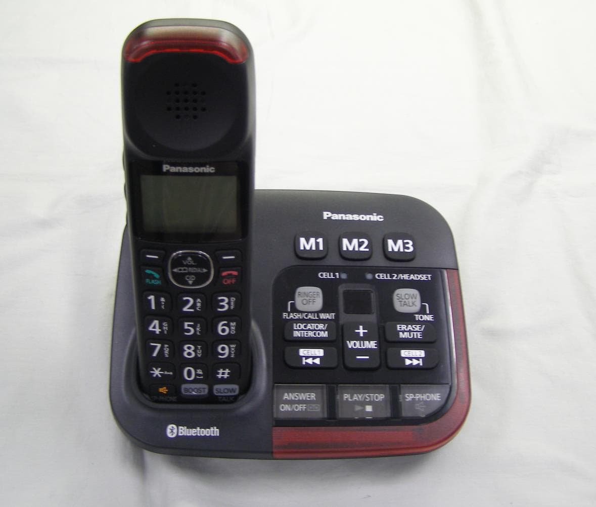
Click to zoom
Application Details
- Equipment Class
- PUB - Part 15 Unlicensed PCS Base Station
- Date of Grant
- Jul 08, 2021
- Application Purpose
- Original Equipment
- Date of Application
- Jul 08, 2021
- Equipment Note
- UPCS Cordless Telephone Base Station with Bluetooth Transceiver
- Frequency Range
- 1921.53600000 - 1928.44800000
- Country
- United States
Documents & Files
Document Text
Text extracted from the exhibit documents filed with the FCC. Open a document above to read the original.
Users Manual
Operating Instructions Amplified Cordless Telephone Model No. KX-TGM430 KX-TGM460 Before initial use, see “Getting Started” on page 13. Thank you for purchasing a Panasonic product. Please read these operating instructions before using the unit and save them for future reference. Consulte “Guía Rápida Española”, página 96. For assistance, visit our Web site: http://shop.panasonic.com/support for customers in the U.S.A. Please register your product: http://shop.panasonic.com/support Introduction Model composition .................4 Accessory information ............4 Graphical symbols for use on equipment and their descriptions ............................7 Important Information For your safety .......................8 Important safety instructions ...........................10 For best performance ...........10 Other information ..................11 Specifications .......................12 Getting Started Setting up .............................13 Controls ................................18 Display icons/Indicators ........21 Language settings ................23 Date and time .......................24 Recording your greeting message ...............................24 Other settings .......................25 Accessibility Accessibility ..........................26 Tone control .........................26 Volume booster ....................27 Speech booster (making your voice louder) .........................29 Talking keypad and phonebook ............................29 Key tones .............................30 Message indicator ................31 Slow talk ...............................32 Using assistive listening devices .................................32 Link to Cell Link to cell feature ................35 Pairing a cellular phone ........35 Link to cell settings ...............36 Making/Answering Calls Making cellular calls .............39 Making landline calls ............40 Answering calls ....................40 Useful features during a call ........................................41 Intercom ...............................44 Call Block Call block ..............................46 Storing unwanted callers ......46 Phonebook Phonebook ...........................49 Memory dial ..........................51 Programming Menu list ...............................53 Alarm ....................................62 Silent mode ..........................63 Other programming ..............63 Registering a unit .................64 Caller ID Service Using Caller ID service .........65 Caller list ...............................65 Using Bluetooth ® Devices Copying phonebook from a cellular phone (phonebook transfer) ................................68 2 Table of Contents Link to Cell app .....................69 Text message (SMS) alert ....70 Alert settings for your DECT phone ...................................70 Using a Bluetooth headset (optional) ..............................71 Answering System for Landline Answering system for landline .................................73 Turning the answering system on/off ....................................73 Greeting message ................73 Listening to messages ..........74 Advanced new message alerting features ....................76 Remote operation .................77 Answering system settings ...78 Useful Information Voicemail service for landline .................................80 Wall mounting .......................81 Error messages ....................83 Troubleshooting ....................84 FCC and other information ...93 Guía Rápida Española Guía Rápida Española .........96 Appendix Customer services ..............109 Limited Warranty (ONLY FOR U.S.A.) ................................110 Index Index....................................112 3 Table of Contents Model composition SeriesModel No. Base unitHandset Part No.Part No.Quantity KX-TGM430 seriesKX-TGM430KX-TGM430KX-TGMA441 KX-TGM460 seriesKX-TGM460KX-TGM460KX-TGMA451 Accessory information Supplied accessories No.Accessory item/Part numberQuantity A AC adaptor *1, *2 1 B Telephone line cord/PQJA10075Y *2 1 CWall mounting adaptor/PNKL1001X11 D Base battery cover *3 /PNYNTGM460MH 1 E Rechargeable batteries *4, *5 4 F Handset cover *6 /PNYNTGMA44BR 1 G Belt clip *7 /PNKE2076Z2 1 *1 PNLV226-0X: KX-TGM430 PNLV236-0Y: KX-TGM460 *2 The AC adaptor and telephone line cord come connected to the base unit at the time of shipment. *3 The base battery cover comes attached to the handset at the time of shipment. *4 The supplied rechargeable batteries in the handset and base unit are installed with yellow insulation sheets inserted between battery ends and the terminals at the time of shipment. Remove the yellow insulation sheets before use. *5 See page 5 for replacement battery information. *6 The handset cover comes attached to the handset at the time of shipment. *7 The belt clip comes attached to the handset at the time of shipment. ABCDE FG 4 For assistance, please visit http://shop.panasonic.com/support Introduction Additional/replacement accessories Please contact your nearest Panasonic dealer for sales information (page 109). Accessory itemModel number/Specifications Rechargeable batteries HHR-4DPA *1 RTo order, please visit http://shop.panasonic.com/support Battery type: – Nickel metal hydride (Ni-MH) – 2 x AAA (R03) size for each handset HeadsetKX-TCA93, KX-TCA430 Range extender KX-TGA407 *2 Key detector KX-TGA20 *3 *1 Replacement batteries may have a different capacity from that of the supplied batteries. *2 By installing this unit, you can extend the range of your phone system to include areas where reception was previously not available. This product can be purchased online. Please visit our Web site: http://shop.panasonic.com/support *3 By registering the key detector (4 max.) to a Panasonic Digital Cordless Phone and attaching it to an easy-to-lose item in advance, you can locate and find the mislaid item to which the key detector is attached. Please visit our Web site: http://www.panasonic.c…
Text truncated - open the document above for the full version.
Cover Letter(s)
Two Riverfront Plaza | Newark, NJ 07102-5490 Ben Botros, Project Manager Safety , Compliance and Quality Assurance Authorization Letter June 28, 2021 PCTP-21-F011 Federal Communication Commission Equipment Authorization Division / Application Processing Branch 7435 Oakland Mills Road Columbia, Maryland 21046 To whom it may concern; Panasonic Corporation of North Amer ica hereby authorizes Nemko AS to act on our behalf in all matters relating to the preparation of TCB Certification application for the below described product. Any and all acts carried out by Nemko AS on our behalf shall have the same effects as acts of our own for a period of six months from the date of this letter. Type Filing: Original Application for UPCS Cordless Telephone Base Station FCC ID: ACJ96NKX-TGM430A FCC Classification: Spread Spectrum Transmitter (DSS) / BT Transceiver in UPCS Base Station FCC Rule Part: FCC Part 15, Subpart C, Section 15.247 Frequency Range: 2402~ 2480 MHz Number Channels: 79 Channels Type Modulation: Digital (Gaussian Frequency Shift Keying) FCC Classification: Isochronous UPCS Base Station (PUB) FCC Rule Part: FCC Part 15, Subpart D Frequency Range: 1921.536 ~ 1928.448 Number Channels: 5 RF Channels / 5x12 = 60 TDMA Duplex Channels RF Exposure: Mobile / MPE (requires minimum 20cm spacing between antenna and body) FCC Rule Part: FCC Part 15, Subpart B FCC Classification: Class B Digital Device (JAB) Responsible Panasonic Corporation of North America Applicant & Grantee: Two Riverfront Plaza, 9 th Floor, Newark, NJ 07102-5490 Sincerely yours, Ben Botros Project Manager Panasonic Corporation of North America Safety, Compliance and Quality Assurance
Cover Letter(s)
Two Riverfront Plaza | Newark, NJ 07102-5490 Ben Botros, Project Manager Safety , Compliance and Quality Assurance Request for Confidentiality June 28, 2021 PCTP-21-F011 Federal Communication Commission Equipment Authorization Division / Application Processing Branch 7435 Oakland Mills Road Columbia, Maryland 21046 To whom it may concern; Panasonic Corporation of North America hereby authorizes Nemko AS to act on our behalf in all matters relating to the preparation of TCB Certification application for the below described product. Any and all acts carried out by Nemko AS on our behalf shall have the same effects as acts of our own for a period of six months from the date of this letter. Type Filing: Original Application for UPCS Cordless Telephone Base Station FCC ID: ACJ96NKX-TGM430A FCC Rule Part: FCC Part 15, Subpart B (JAB), C (DTS) and D (UPCS) Request For Permanent Confidentiality In accordance with provisions of Sections §§0.457(d) and 0.459 of the Commission’s Rules and Section 552(b)(4) of the Freedom of Information Act, we request permanent confidentiality for exhibits, which contain: (1) Description of Electrical Circuitry; (2) Schematic Diagrams of Base Unit and RF Unit; and (3) Base Unit Block Diagram. The transm itter is not user adjustable and does not have a Tune-Up Procedure. These exhibits contain proprietary, confidential and trade secrets material, which would not be routinely made available for public inspection. Request For Short-Term Confidentiality In accordance with FCC Public DA 04-1705, we request 180 day short-term confidentiality, starting from the from the issuance of equipment authorization date, for exhibits, which contain: (1) External Photographs of Base Unit and RF Unit; (2) Internal Photographs of Base Unit and RF Unit; (3) Test Setup Photographs; and (4) User Manual. These exhibits contain pre-market information, which could give our competitors unfair advantage should this information be released before this product is actually introduced into the common marketplace. Sincerely yours, Ben Botros Project Manager Panasonic Corporation of North America Product Safety and Compliance Department
Cover Letter(s)
Date: June 30th , 2021 DESCRIPTION OF SIMILARITY between ORIGINAL and SIMILARITY SIMILARITY Model No. : KX-TGM460/ KX-TGM430 (Base Unit) FCC ID: ACJ96NKX-TGM460A / ACJ96NKX-TGM430A (under application) ORIGINAL Model No. : KX-TGM460/ KX-TGM430 (Base Unit) FCC ID: ACJ96NKX-TGM460 / ACJ96NKX-TGM430 ORIGINAL MODEL SIMILAR MODEL KX-TGM460/ KX-TGM430 KX-TGM460/ KX-TGM430 Main P.C. Board P.C. Board is identical (Both use the same PCB, PNLB2574) DECT part DECT part is identical. AC adaptor KX-TGM460 use the same AC adaptor, PNLV236 KX-TGM430 use the same AC adaptor, PNLV226 We declare that the Main P.C. Board and DECT part between Original and Similar model for KX-TGM460/ KX-TGM430 are identical.
Cover Letter(s)
FCC Part 15D – Compliance Information Nemko AS, Instituttveien 6, 2007 Kjeller, Norway kx-tgm430_fcc part 15d declarations.docx Tel: +47 22 96 03 30 Fax: +47 22 96 05 50 Page 1 (4) rev.3.0 24-June- 2019 Email: [email protected] EUT AND PRODUCT INFORMATION Type of Equipment UPCS (DECT 6.0) Applicant Name Panasonic Corporation of North America Address Two Riverfront Plaza, 9th floor Newark, NJ 07102-5490, USA. Contact Ben Botros Phone 201-348-7760 Email [email protected] Brand Name Panasonic BASE STATION HANDSET / PORTABLE Wireless Relay Station / Repeater EUT Type/System ܈ ܆ ܆ Modular Approval ܆ YES ܆ LMA ܆ YES ܆ LMA ܆ YES ܆ LMA FCC ID ACJ96NKX-TGM430A ISED ID (Canada) Model name KX-TGM430 HVIN KX-TGM430 PMN KX-TGM430 HW Version MP SW Version SW402 Maximum Antenna Gain 0dBi Is EUT Initiating Device ☐ YES ܆ YES ܆ YES Does EUT transmit signaling channels ☒ YES ܆ YES ܆ YES Number of slots in use simultaneously 1 slot Frequency Band 1921.536 – 1928.448 MHz Number of RF Channels 5 Frame Period 10 ms Max. Burst length 417us / duplex channel Min. Burst Length 106us / signaling channel Number of System Channels 60 (12 duplex channels per RF carrier) Supported DECT Slot Types ܈ Full Slot ܆ Long Slot ܆ Double Slot Operating Mode ܆ Simplex ܈ Duplex ANTENNA DIVERSITY Antenna Diversity Supported TX RX Base Station 1 ܈ ܈ 2 ܈ ܈ 3 ܆ ܆ 4 ܆ ܆ Handset 1 ܆ ܆ 2 ܆ ܆ FCC Part 15D – Compliance Information Nemko AS, Instituttveien 6, 2007 Kjeller, Norway kx-tgm430_fcc part 15d declarations.docx Tel: +47 22 96 03 30 Fax: +47 22 96 05 50 Page 2 (4) rev.3.0 24-June- 2019 Email: [email protected] ANTENNAS Base Station Antenna Type Internal External 1 Wired Antenna ܈ ܆ 2 Pattern Antenna ܈ ܆ 3 ܆ ܆ 4 ܆ ܆ Does RX and TX use the same antenna(s)? ܈ Yes ܆ No Handset Antenna Type Internal External 1 ܆ ܆ 2 ܆ ܆ 3 ܆ ܆ Does RX and TX use the same antenna(s)? ܆ Yes ܆ No VOLTAGE AND TEMPERATURE RANGES VOLTAGES Base Station Handset or Portable WRS Nominal Voltage 120V AC Cut-Off Voltage (if applicable) - POWER SOURCE Type Manufacturer Base Station or WRS PNLV226 (AC Adaptor) Panasonic Handset (Charger) Connections on Base ܈ PSTN ☐ USB ☐ Ethernet ☐ Others (please specify) .... ANCILLARY EQUIPMENT Description AC Adaptor Type PNLV226 (AC Adaptor) Manufacturer Panasonic HOST DEVICE Description Type Manufacturer ADDITIONAL INFORMATION FCC Part 15D – Compliance Information Nemko AS, Instituttveien 6, 2007 Kjeller, Norway kx-tgm430_fcc part 15d declarations.docx Tel: +47 22 96 03 30 Fax: +47 22 96 05 50 Page 3 (4) rev.3.0 24-June- 2019 Email: [email protected] MANUFACTURERS DECLARATIONS FCC part 15.323 (c)(5) The applicant declares that the system in this application has more than 20 duplex system access channels defined, and that the system is operating in Least Interfered Channel (LIC) mode in accordance with this section. Applicant Agrees ܈܈ Yes ܆܆ No FCC part 15.323 (c)(5) No device or group of co-operating devices located within 1m of each other shall during any frame period occupy more than 6 MHz of aggregate bandwidth, or alternatively, more than one third of the time and spectrum windows defined by the system. Applicant Agrees ܈܈ Yes ܆܆ No FCC part 15.323 (c)(10) The applicant hereby declares that the system in this application does use the criteria of (c)(10) of this section. Applicant Agrees ܈܈ Yes ܆܆ No FCC part 15.323 (c)(11) The applicant hereby declares that system in this application does not use the criteria of (c)(11) of this section. Applicant Agrees ܈܈ Yes ܆܆ No FCC part 15.323 (c)(12) The provisions of (c)(10) or (c)(11) of this section shall not be used to extend the range of spectrum occupied over space or time for the purpose of denying fair access to spectrum to other devices. Applicant Agrees ܈܈ Yes ܆܆ No ADDITIONAL REMARKS: > DECLARED BY: June 29, 2021 Ben Botros FCC Part 15D – Compliance Information Nemko AS, Instituttveien 6, 2007 Kjeller, Norway kx-tgm430_fcc part 15d declarations.docx Tel: +47 22 96 03 30 Fax: +47 22 96 05 50 Page 4 (4) rev.3.0 24-June- 2019 Email: [email protected] About this document This document specifies the information that is needed to select the correct testcases and test procedures for testing to FCC Part 15D. The form must be completed by the applicant and submitted to Nemko before testing is started. Preparation of Equipment for Testing Note (a): Number of samples for testing The following samples are needed for FCC 15D testing: RF Conducted Tests: One sample with a 50 ohm antenna connector (preferably SMA Female). Only one antenna connector is needed for these tests even if the equipment has more than one antenna. Monitoring Tests: One sample with 50 ohm antenna connectors fitted to all antennas (preferably SMA female). Additionally we need a companion device that will work together with the EUT, the companion device must also have antenna connectors on all antennas. Radiated Tests: One sample with integral antennas. This sample will be used to measure Antenna Gain, Part 15B and Power-Line Conducted tests. Note (b): Burst Mode All RF tests are performed with the EUT in force transmit, aka burst mode. Software and necessary programming tools must be submitted to Nemko together with the test samples before start of testing. Note (c): Monitoring Tests Monitoring tests are performed in normal operating mode by establishing a connection from the handset (or the initiating device) to the base station (or the responding device). Most tests are performed by establishing connections from the initiating device to the responding device and observing which channel and/or timeslot is used. For monitoring tests we need a EUT and a Companion device that both have antenna connectors on all antennas (preferably SMA female, again). Additionally, we need access to the CLK100 signal on the Base Station, this is necessary because some of the tests require that the interferers are synced to the DECT frame. Note (d): Connection to an external power supply Means of c…
Text truncated - open the document above for the full version.
Cover Letter(s)
Date: March 26th, 2021 DESCRIPTION OF SIMILARITY between ORIGINAL and SIMILARITY Name of Appliance : 2.4GHz Frequency Hopping Transmitter (FCC part 15.247) SIMILARITY Model No. : KX-TGM430 (Base Unit) FCC ID: ACJ96NKX-TGM430A ORIGINAL Model No. : KX-TGD860 (Base Unit) Approval Date : Dec 2020. Approved. FCC ID: ACJ96NKX-TGD860 BASIC MODEL SIMILAR MODEL KX-TGD860 KX-TGM430 Bluetooth Module Software Suffix No. 99-PNXA1032xx Suffix No. 99-PNXA1015xx AC adaptor Both models are used to PNLV226 AC adaptor. P.C Board of Bluetooth Module are common. Bluetooth module We declare that the Bluetooth module of KX-TGD860 and KX-TGM430 are identical in hardware. Regarding the test with conducted of FCC part 15.247 (2.4GHz Frequency Hopping Transmitter), the test of KX-TGM430 are packaged for the test of KX-TGD860 with the following items. (1) Bluetooth Module for both models are common. (2) AC adaptor for both models are same PNLV226. *As the Bluetooth module in KX-TGM430 (FCC ID: ACJ96NKX-TGM430A) is identical to the Bluetooth Module in KX-TGD860 (FCC ID: ACJ96NKX-TGD860), the test results of Nemko Test Report No: xxxxx-x for KX-TGD860 continue to be valid for the Bluetooth part in FCC ID: ACJ96NKX-TGM430A.
External Photos
EXTERNAL PHOTOGRAPHS KX-TGM430 Top View Bottom View
ID Label/Location Info
EXHIBIT B MARKINGS Base Unit: The base unit provides with the following marking, or equivalent. This device complies with Part 15 of the FCC rules. Operation is subject to the following two conditions: (1) This device may not cause harmful interference, and (2) this device must accept any interference received, including interference that may cause undesired operation. Privacy of communications may not be ensured when using this phone. NOTE: Above markings are shown on bottom of the base unit.
Internal Photos
INTERNAL PHOTOGRAPHS Internal View Main Board <Opposite side>
RF Exposure Info
FCC ID: ACJ96NKX-TGM430A RF Exposure Compliance for Simultaneous Operations Configurations for Simultaneous OperationsConfiguration 1: DECT + BluetoothPower Density is calculated from Maximum Conducted Power and Antenna Gain at prediction distance RF Function DECT BT Frequency (MHz) 1925 2402 Conducted Output Power (dBm) 18.60 8.30 Tune Up Tolerance (dB) 1.40 0.00 Output Power incl. Tune Up Tolerance (W) 0.100 0.007 Antenna Gain (dBi) 0.00 0.00 Antenna Gain (Numeric) 1.00 1.00 Prediction Distance (cm) 20 20 Σ of MPE Time Averaged Duty Cycle (%) 100 100 ratios Calculated Power Density (W/m2) 0.199 0.013 Requirement (W/m2) 10.000 10.000 MPE ratio (Power Density/Requirement) 0.020 0.001 Configuration 1 (MPE Ratio) 0.020 0.001 0.021 Requirement: Σ of MPE ratios ≤ 1
Test Report
Report No. 440845-16-R01 Template version: C Nemko Norway Nemko AS, Instituttveien 6, P.O. Box 96 Kjeller, 2007 Kjeller, Norway TEL +47 22 96 03 30 FAX +47 22 96 05 50 EMAIL [email protected] ENTERPRISE NUMBER NO974404532 nemko.com/no Test Report Product UPCS Base Station with Bluetooth Transceiver Name and address of the applicant Panasonic Corporation of North America Two Riverfront Plaza, 9 th Floor Newark, 07102-5490, NJ, USA Name and address of the manufacturer Panasonic Corporation 1-62, 4-chome, Minoshima, Hakata-ku Fukuoka, 812-8531, Japan Model KX-TGM430 Rating 120V 60Hz (Input: 120V ~60Hz 0.1A; Output: 5.5V 0.5A, 2.75W) Trademark Panasonic Serial number / Additional information DECT 6.0, Bluetooth 4.2, GFSK only Tested according to FCC Part 15, subpart D Isochronous UPCS Device, 1920 – 1930 MHz Industry Canada RSS 213, Issue 3 2 GHz License-Exempt Personal Communications Services (LE-PCS) Devices Order number 440845 Tested in period 2016.02.04 to 2016.02.22 and 2021-06-16 Issue date 2021.06.30 Name and address of the testing laboratory Instituttveien 6 Kjeller, Norway CAB Number: FCC: NO0001 ISED: NO0470 TEL: +47 22 96 03 30 FAX: +47 22 96 05 50 Prepared by [Frode Sveinsen] Approved by [G.Suhanthakumar] This report shall not be reproduced except in full without the written approval of Nemko. Opinions and interpretations expressed within this report are not part of the current accreditation. This report was originally distributed electronically with digital signatures. For more information please contact Nemko. TEST REPORT FCC part 15D Report no.: 440845-16-R01 FCC ID: ACJ96NKX-TGM430A Nemko Norway, Instituttveien 6, Kjeller, Norway Page 2 (44) CONTENTS 1 INFORMATION ................................................................................................................................. 3 1.1 Tested Item ........................................................................................................................................ 3 1.2 Description of Tested Device ............................................................................................................. 3 1.3 Test Environment ............................................................................................................................... 4 1.4 Test Engineer(s) ................................................................................................................................ 4 1.5 Test Equipment .................................................................................................................................. 4 1.6 Antenna Requirement ........................................................................................................................ 4 1.7 Other Comments ............................................................................................................................... 4 2 TEST REPORT SUMMARY .............................................................................................................. 5 2.1 General .............................................................................................................................................. 5 2.2 Test Summary ................................................................................................................................... 6 3 TEST RESULTS ................................................................................................................................ 7 3.1 Power Line Conducted Emissions ..................................................................................................... 7 3.2 Channel Frequencies ......................................................................................................................... 9 3.3 Automatic Discontinuation of Transmission ....................................................................................... 9 3.4 Peak Power Output .......................................................................................................................... 10 3.5 Emission Bandwidth B ..................................................................................................................... 13 3.6 Power Spectral Density ................................................................................................................... 16 3.7 In-Band Unwanted Emissions, Conducted ...................................................................................... 19 3.8 Out-of-band Emissions, Conducted ................................................................................................. 21 3.9 Carrier Frequency Stability .............................................................................................................. 27 3.10 Frame Repetition Stability ................................................................................................................ 28 3.11 Frame Period and Jitter ................................................................................................................... 28 3.12 Monitoring Threshold, Least Interfered Channel .............................................................................. 30 3.13 Threshold Monitoring Bandwidth ..................................................................................................... 32 3.14 Reaction Time and Monitoring Interval ............................................................................................ 33 3.15 Time and Spectrum Window Access Procedure .............................................................................. 35 3.16 Acknowledgements and Transmission Duration .............................................................................. 38 3.17 Dual Access Criteria Check ............................................................................................................. 39 3.18 Alternative Monitoring Interval ................................................................................................…
Text truncated - open the document above for the full version.
Test Setup Photos
TEST SET-UP PHOTOS Project no.: 440845 FCC ID: ACJ96NKX-TGM430A Page 1 (1) Radiated Emissions 30 – 1000 MHz Radiated Emissions 1 – 18 GHz Power-Line Conducted Emissions
Contact Information
Applicant
Ben Botros(Manager - Regulatory & Compliance)
Test Firm
Nemko Scandinavia ASFrode Sveinsen
[email protected]+4796905548
Technical Specifications
| # | Rule Parts | Frequency Range | Power Output |
|---|---|---|---|
| 1 | 15D | 1.92 GHz - 1.93 GHz | 72.00 mW |
Other Applications from Panasonic Corporation of North America
ACJ-EAH-A1000
Aug 19, 2026Digital Wireless Stereo Headphones
Equipment Class
DSS - Part 15 Spread Spectrum TransmitterACJ9TGFZVNF3G1
Jun 16, 2026Contactless Smart Card Reader
Equipment Class
DXX - Part 15 Low Power Communication Device Transmitter
ACJ932AM2301
Jan 29, 2025Car AV Control Unit for CDC
Equipment Class
DTS - Digital Transmission SystemACJ96NKX-TGEA60B
Aug 13, 2024DECT Handset
Equipment Class
PUE - Part 15 Unlicensed PCS portable Tx held to earACJ96NKX-TGE630B
Aug 12, 2024DECT Base Unit
Equipment Class
PUB - Part 15 Unlicensed PCS Base Station