ACJ96NKX-UDS124DECT 6.0 Cordless Telephone Base Station for SIP server or PBX
Panasonic Corporation of North America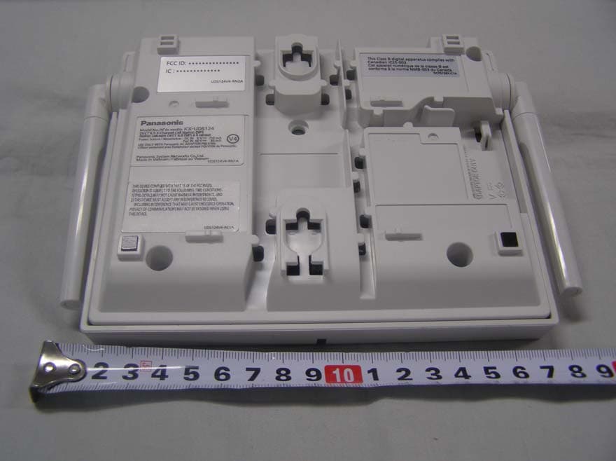
Click to zoom
Application Details
- Equipment Class
- PUB - Part 15 Unlicensed PCS Base Station
- Date of Grant
- May 28, 2012
- Application Purpose
- Original Equipment
- Date of Application
- May 28, 2012
- Equipment Note
- DECT 6.0 Cordless Telephone Base Station for SIP server or PBX
- Frequency Range
- 1921.53600000 - 1928.44800000
- Country
- United States
Documents & Files
Document Text
Text extracted from the exhibit documents filed with the FCC. Open a document above to read the original.
Users Manual
Model No. KX-UDS124 DECT 6.0 Cell Station Unit (SIP) Installation Guide Thank you for purchasing this Panasonic product. Please read this manual carefully before using this product and save this manual for future use. KX-UDS124: Software File Version 01.000 or later Table of Contents 1 For Your Safety ........................................................................................3 2 Overview ...................................................................................................9 3 Installing the SIP Cell Stations .............................................................15 3.1 Overview of SIP Cell Stations ........................................................................................15 3.2 Connecting SIP Cell Stations .........................................................................................17 3.3 Wall Mounting ..................................................................................................................19 3.4 Basic Network Configuration .........................................................................................21 4 Deployment Procedure ..........................................................................25 4.1 Overview ..........................................................................................................................25 4.2 Site Planning ...................................................................................................................27 4.3 Site Survey .......................................................................................................................34 4.4 CS Registration ...............................................................................................................41 4.5 Tree Survey ......................................................................................................................43 4.6 Configuration ...................................................................................................................45 4.7 PS Registration ...............................................................................................................47 4.8 PS Area Check .................................................................................................................51 5 Troubleshooting .....................................................................................52 6 Appendix .................................................................................................54 2Installation Guide Table of Contents 1 For Your Safety To prevent personal injury and/or damage to property, be sure to observe the following safety precautions. The following symbols classify and describe the level of hazard and injury caused when this unit is operated or handled improperly. WARNING This notice means that misuse could result in death or serious injury. CAUTION This notice means that misuse could result in injury or damage to property. The following types of symbols are used to classify and describe the type of instructions to be observed. This symbol is used to alert users to a specific operating procedure that must not be performed. This symbol is used to alert users to a specific operating procedure that must be followed in order to operate the unit safely. WARNING •Do not connect or disconnect the AC plug with wet hands. •Do not touch the SIP-CS, AC adaptor, or AC adaptor cord during a lightning storm. •Do not allow anything to rest on the AC adaptor cord or LAN cable. Do not locate the SIP-CS where the AC adaptor cord or LAN cable may be stepped on or tripped on. •When installing or testing a SIP-CS with an external AC adaptor, the AC adaptor should be plugged into a wall outlet or floor-mounted AC outlet. Do not connect the AC adaptor to a ceiling-mounted AC outlet, as the weight of the adaptor may cause it to become disconnected. •Make sure that you do not short the battery or cables. •Never attempt to insert wires, pins, etc. into the vents or other holes of the SIP-CS. •Do not splash water on the AC adaptor or the power cord, nor get them wet. Doing so can result in fire, electric shock, or injury. If they do get wet, immediately disconnect the AC adaptor and power cord, and contact an authorized service center. •Do not touch the AC adaptor for extended periods of time. Doing so can lead to low-degree burns. •Do not make power connections that exceed the ratings for the AC outlet or power equipment. If the power rating of a surge protector, etc. is exceeded, it can cause a fire due to heat buildup. •Care should be taken so that objects do not fall onto, and liquids are not spilled into, the SIP-CS. Do not subject the SIP-CS to excessive smoke, dust, moisture, mechanical vibration, shock, or direct sunlight. •Do not place heavy objects on top of the SIP-CS. •Do not mount the SIP-CS in a manner other than that described in this manual. Installation Guide3 1 For Your Safety •The SIP-CS must only be installed and serviced by qualified service personnel. The SIP-CS should be used as-is from the time of purchase; it should not be disassembled or modified. Disassembly or modification can cause a fire, electric shock, or damage to the SIP-CS. •Make sure that the wall that the SIP-CS will be attached to is strong enough to support the SIP-CS (approx. 330 g [11.6 oz]). If not, it is necessary for the wall to be reinforced. •Only use the wall-mounting equipment (screws, washers, wall mounting plate) included with the SIP-CS. •When the SIP-CS is no longer in use, make sure to detach it from the wall. •Disconnect the SIP-CS from the AC outlet, disconnect the LAN cable, and contact the dealer if: –The AC adaptor cord or AC plug becomes damaged or frayed. –The SIP-CS is exposed to rain, water, or any other liquid. –The SIP-CS is dropped or damaged. –Internal components are exposed due to damage. –The SIP-CS does not operate properly. –Performance deteriorates. •Disconnect the SIP-CS from the AC outlet and di…
Text truncated - open the document above for the full version.
Cover Letter(s)
EXHIBIT A STATEMENT OF SECURITY CODE This cordless telephone system has more than 1,000 billion combinations that are provided by the following means: ∑ Provided with 128 bits for security codes. ∑ When shipped from the factory, the security code is decided by the manufacture. It is memorized in a memory IC. ∑ Base and Handset knows each other’s security code information.
Cover Letter(s)
Panasonic Corporation of North America One Panasonic Way 4B-8 Secaucus, NJ 07094 Tel: 201-348-7758 / Fax: 201-392-4564 [email protected] Richard Mullen Group Manager Product Safety and Compliance Division Power of Attorney May 24, 2012 PCNF-12-F025 Federal Communication Commission Equipment Authorization Division / Application Processing Branch 7435 Oakland Mills Road Columbia, Maryland 21046 To whom it may concern; Panasonic Corporation of North America hereby authorizes Nemko AS to act on our behalf in all matters relating to the preparation of TCB Certification application for the below described product, which are in compliance with FCC Part 15D. Any and all acts carried out by Nemko AS on our behalf shall have the same effects as acts of our own for a period of one year from the date of this letter. Type Filing: Original Application for DECT 6.0 Cordless Telephone Base Station for SIP Server or PBX, Model KX-UDS124 Product Classification: Part 15 Unlicensed PCS Base Station / Equipment Code PUB FCC ID Handset Unit ACJ96NKX-UDS124 FCC Rule Part: FCC Part 15, Subpart D 1 Frequency Range: 1921.536 ~ 1928.448 MHz RF Output Power: 87.0 mW Power Supply: AC Adaptor, Mode l PQLV206 with switching power supply at 36 kHz Responsible Panasonic Corporation of North America Applicant & Grantee: One Panasonic Way, Secaucus, NJ 07094 FRN Number: 0003762242 Responsible Manufacturer: Panasonic System Networks Co., Ltd. Sincerely yours, Richard Mullen Richard Mullen Group Manager Panasonic Corporation of North America Product Safety and Compliance Division 1 The subject DECT 6.0 Cordless Telephone Base Station may be used with DECT Handset, Models KX-UDT111 and KX-UDT121, which will be FCC Part 15D certified under FCC IDs: ACJ96NKX- UDT111 and ACJ96NKX- UDT121. Panasonic Corporation of North America One Panasonic Way 4B-8 Secaucus, NJ 07094 Tel: 201-348-7758 / Fax: 201-392-4564 [email protected] Richard Mullen Group Manager Product Safety and Compliance Division Request for Confidentiality May 24, 2012 PCNF-12-F025 Federal Communication Commission Equipment Authorization Division Application Processing Branch 7435 Oakland Mills Road Columbia, Maryland 21046 To whom it may concern; Type Filing: Original Application for DECT 6.0 Cordless Telephone Base Station for SIP Server or PBX, Model KX-UDS124 Product Classification: Part 15 Unlicensed PCS Base Station / Equipment Code PUB FCC ID Handset Unit ACJ96NKX-UDS124 In accordance with provisions of Sections 0.457 and 0.459 of the Commission’s Rules and Section 552(b)(4) of the Freedom of Information Act, we request permanent confidentiality for exhibits, which contain: (1) Antennas Construction; (2) Description of Electrical Circuitry; (3) Schematic Diagrams of Base Unit and RF Unit; and (4) Block Diagram. The transmitter is not user adjustable and does not have a Tune-Up Procedure. These exhibits contain proprietary, confidential and trade secrets material, which would not be routinely made available for public inspection. In accordance with FCC Public DA 04-1705, we request forty-five day short-term confidentiality, starting from the from the issuance of equipment authorization date, for exhibits, which contain: (1) External Photographs of Base Unit and RF Unit; (2) Internal Photographs of Base Unit and RF Unit; (3) Test Setup Photographs; and (4) User Manual. These exhibits contain pre-market information, which could give our competitors unfair advantage should this information be released before this product is actually introduced into the common marketplace. Sincerely yours, Richard Mullen Richard Mullen Group Manager Panasonic Corporation of North America Product Safety and Compliance Division
Cover Letter(s)
FCC Part 15D – Compliance Information uds_udt series part 15d declarations.doc 6-Feb-2012 page 1 (4) rev.1.5 EUT AND PRODUCT INFORMATION Type of Equipment UPCS (DECT 6.0) Applicant Name Panasonic Corporation of North America Responsible Mfr Name Panasonic System Networks Co., Ltd. Address 1-62, 4-chome, Minoshima, Hakata-ku, Fukuoka 812-8531, Japan Contact Michihito Miyazaki FP PP PP EUT Type/System FCC ID ACJ96NKX-UDS124 ACJ96NKX-UDT111 ACJ96NKX-UDT121 Industry Canada ID 216A-KXUDS124 216A-KXUDT111 216A-KXUDT121 Model name KX-UDS124 KX-UDT111 KX-UDT121 HW Version PNLB1925ZAxx PNLB1926ZAxx PNLB2026ZBxx SW Version SW014 SW049 SW045 Max antenna Gain 2dBi ANT1: 1.5dBi ANT2: 1.0dBi ANT1: 1.5dBi ANT2: 0.5dBi BT-ANT: -1.5dBi Can the EUT be Initiating Device YES YES YES Does the EUT transmit signaling channels YES YES YES Max number of slots in use simultaneously 6 slot 1 slot 1 slot Test standard: FCC part 15D RSS-213, Issue 2 / RSS-GEN, Issue 3 Frequency Band 1921.536 – 1928.448 MHz # of RF Channels 5 Frame Period 10 ms Max. Burst length 723us / duplex channel Min. Burst Length 106us / signaling channel # of System Channels 60 (12 duplex channels per RF carrier) Operating Mode Simplex Duplex FCC Part 15D – Compliance Information uds_udt series part 15d declarations.doc 6-Feb-2012 page 2 (4) rev.1.5 ANTENNAS Base (FP) Antenna Type Internal External 1 Dipole Antenna 2 Dipole Antenna 3 4 Does RX and TX use the same antenna(s)? Yes No Handset (PP) Antenna Type Internal External 1 Pattern Antena(KX-UDT111) Wired Antenna(KX-UDT121) 2 Wired Antenna Does RX and TX use the same antenna(s)? Yes No ANTENNA DIVERSITY Antenna Diversity Supported TX RX Base (FP) 1 2 3 4 Handset (PP) 1 2 VOLTAGE AND TEMPERATURE RANGES VOLTAGES FP PP(KX-UDT111) PP(KX-UDT121) Nominal Voltage 120V AC DC 2.6V DC 3.7V Cut-Off Voltage (if applicable) - 2.35V 3.35V POWER SOURCE Type Manufacturer Base or Repeater PNLV226 (AC Adaptor) Panasonic Handset (PP) (charger) PNLC1024(KX-UDT111) PNLC1032(KX-UDT121) Panasonic Data Connections PSTN Others (please specify) ....LAN(RJ-45) FCC Part 15D – Compliance Information uds_udt series part 15d declarations.doc 6-Feb-2012 page 3 (4) rev.1.5 ANCILLARY EQUIPMENT Description AC Adaptor and Charger Type PNLV226 (AC Adaptor) PNLC1024(Charger for KX-UDT111) PNLC1032(Charger for KX-UDT121) Manufacturer Panasonic HOST DEVICE Description Type Manufacturer ADDITIONAL INFORMATION FCC Part 15D – Compliance Information uds_udt series part 15d declarations.doc 6-Feb-2012 page 4 (4) rev.1.5 MANUFACTURERS DECLARATIONS FCC part 15.323 (c)(5) The applicant declares that the system in this application has more than 40 duplex system access channels defined, and that the system is operating in Least Interfered Channel (LIC) mode in accordance with this section. Applicant Agrees Yes No FCC part 15.323 (c)(5) No device or group of co-operating devices located within 1m of each other shall during any frame period occupy more than 6 MHz of aggregate bandwidth, or alternatively, more than one third of the time and spectrum windows defined by the system. Applicant Agrees Yes No FCC part 15.323 (c)(10) The applicant hereby declares that the system in this application does use the criteria of (c)(10) of this section. Applicant Agrees Yes No FCC part 15.323 (c)(11) The applicant hereby declares that system in this application does not use the criteria of (c)(11) of this section. Applicant Agrees Yes No FCC part 15.323 (c)(12) The provisions of (c)(10) or (c)(11) of this section shall not be used to extend the range of spectrum occupied over space or time for the purpose of denying fair access to spectrum to other devices. Applicant Agrees Yes No FCC part 15.307 (b) The Applicant is a participating member of UTAM, Inc. and will provide an affidavit from UTAM, Inc. certifying this. Confirmed By Applicant Yes No ADDITIONAL REMARKS: > DECLARED BY: 13 April 2012 Date Michihito Miyazaki Name (print) Signature
External Photos
EXHIBIT D-1 EXTERNAL PHOTOGRAPHS
ID Label/Location Info
EXHIBIT B MARKINGS
Internal Photos
EXHIBIT D-2 INTERNAL PHOTOGRAPHS PCB front PCB rear EXHIBIT D-2 INTERNAL PHOTOGRAPHS RF block under the shield
Parts List/Tune Up Info
20120217-018 M O D E L P A R T S L I S T (Ref.No.PNLPUDS124H1ZA-REV001) MODEL: PNLPUDS124H1ZA STEP:D APPROVED DATE:2012/02/23 Panasonic System Networks Co., Ltd. APPLY: E_CLERK: M_CLERK: S_CLERK: O/P DATE:2012/03/05 LEVEL SORT ASSY CODE OR SUPLY PARTS RISK NOT USE PARTS NUMBER MAKER NUMBER REMARKS QT. UNIT PL S_RMKS S_SUM S_ID NOTE 1 PNLPUDS124H1ZA #1AJ1LPUDS124CEHZA #1AJ1 1 PC Inspection and Adjustm ent Standard 1 Z #1PR1LPUDS124CEHZA #1PR1 1 PC Software Preparation2 N #1AJ1LPUDS124HZA #1AP1LPUDS124CEHZA #1AP1 1 PC Manual & Auto Inser t Part 2 #1PR1LPUDS124HZA Z U4V5CA U4V5CA 1 PC MASTER DATA IC102 **** SOFT_VER : **.*** 3 N #1AP1LPUDS124HZA #1RE2LPUDS124CEHZA #1RE2 1 PC Reflow Process3 N Y F4D25105A010 PAS0815LR2R5105G C518,C519 2 PC DOUBLE LAYER CAPACIT OR 3 T K2LC108B0069 TM5RJ3-88(50) JK201 1 PC MODULAR JACK4 N #1RE2LPUDS124HZA #1RE1LPUDS124CEHZA #1RE1 1 PC Reflow Process4 N B0BC06800004 ST03-68F1-5053 D206 1 PC DIODE4 B0EDER000009 S1ZB60-7072 D204,D205 2 PC DIODE4 T B0JCML000007 SM1100A-T D202 1 PC DIODE4 P C0EBE0000269 XC61FC2712MR IC301 1 PC RESET IC4 T X C1CB00002566 KSZ8041NL IC201 1 PC COMMUNICATION IC4 T C1CB00003256 MK5811CMLFT IC304 1 PC COMMUNICATION IC4 N Y C1CB00003640 DE19RF19ZANC IC401 1 PC COMMUNICATION IC4 N C1CB00003680 TPS23750PWPR IC202 1 PC COMMUNICATION IC4 N Y C2HBBY000142 DE56PC147NE4ALC IC302 1 PC IC4 N Y C2HBCY000098 DMW74MB121AE2BBC IC101 1 PC IC4 N * C3ABRY000075 W9825G6JH-6 IC103,IC105,IC106 3 PC DRAM4 N ** C3ABRY000078 EM63A165TSB-7G DRAM4 O ECUE0J105KBQ ECUE0J105KBQ C417,C422 2 PC CAPACITOR ECJ0EB0J105K,F1G 0J1050007,F1G0J105A007 4 O ECUE1A104KBQ ECUE1A104KBQ C413,C418,C419,C424 4 PC ECJ0EB1A104K,F1G1A1040003,F1G1A104A014,F1G1A1040006,F1G1A104A01 2 4 O ECUE1A224KBQ ECUE1A224KBQ C230 1 PC F1G1A2240008 4 O ECUE1C103KBQ ECUE1C103KBQ C211,C301,C337,C341C420 5 PC CAPACITOR ECJ0EB1C103K,F1G1C103A110,F1G1C103A004,F1G1C1030008 ,F1G1C103A048 4 O ECUE1C104KBQ ECUE1C104KBQ C117,C118,C121,C127C128,C131,C132,C133C134,C135,C136,C137C138,C140,C141,C142C143,C204,C333,C334C335,C336,C338,C340C347,C350,C392,C516C521,C523 30 PC CAPACITOR F1G1C104A077 4 O ECUE1H100DCQ ECUE1H100DCQ C402,C407,C412,C421C423,C425 6 PC CAPACITOR ECJ0EC1H100D,F1G1H100A456,F1G1H100A723,F1G1H100A565 4 O ECUE1H101JCQ ECUE1H101JCQ C415 1 PC CERAMIC CAPACITOR ECJ0EC1H101J, F1G1H1010001,F1G1H1010005,F1G1H101A557,F1G1H101A566 4 O ECUE1H120JCQ ECUE1H120JCQ C205,C206 2 PC CERAMIC CAPACITOR ECJ0EC1H 120J,F1G1H120A444,F1G1H120A542,F1G1H120A565,F1G1H120A557 4 O ECUE1H121JCQ ECUE1H121JCQ C416 1 PC CERAMIC CAPACITOR ECJ0EC1H121J, F1G1H121A444,F1G1H121A495,F1G1H121A541,F1G1H121A557 4 O ECUE1H150JCQ ECUE1H150JCQ C227,C324 2 PC CERAMIC CAPACITOR ECJ0EC1H 150J,F1G1H150A444,F1G1H150A542,F1G1H150A565,F1G1H150A557 4 O ECUE1H1R5CCQ ECUE1H1R5CCQ C431,C437 2 PC CERAMIC CAPACITOR ECJ0EC1H 1R5C,F1G1H1R5A445,F1G1H1R5A448,F1G1H1R5A424,F1G1H1R5A577 4 O ECUE1H220JCQ ECUE1H220JCQ C325 1 PC CAPACITOR ECJ0EC1H220J,F1G1H220 0001,F1G1H220A542,F1G1H220A565,F1G1H220A557 4 O ECUE1H3R0CCQ ECUE1H3R0CCQ C439 1 PC ECJ0EC1H030C,F1G1H3R0A445,F1G1H3R0A543,F1G1H3R00002,F1G1H3R0A60 9 4 O ECUE1H471KBQ ECUE1H471KBQ C382,C383,C384,C386C388,C389,C390,C391 8PC ECJ0EB1H471K,F1G1H471A709,F1G1H4710004,F1G1H471A459 4 O ECUE1H561KBQ ECUE1H561KBQ C228 1 PC ECJ0EB1H561K,F1G1H5610004 4 O ECUE1H5R0CCQ ECUE1H5R0CCQ C436 1 PC CAPACITOR ECJ0EC1H050C,F1G1H5R0 A445,F1G1H5R0A543,F1G1H5R0A564,F1G1H5R0A418 4 O ECUV1A225KBV ECUV1A225KBV C426 1 PC CAPACITOR ECJ1VB1A225K,F1H1A225 A003,F1H1A225A025 4 O ECUV1C105KBV ECUV1C105KBV C306 1 PC CAPACITOR F1H1C105A094,F1H1C105 A118,F1H1C105A097 4 O ECUV1E333KBV ECUV1E333KBV C236 1 PC ECJ1VB1E333K,F1H1E333A002,F1H1E333A067,F1H1E333A068,F1H1E333A08 6 4 P EEEFK2A220P EEEFK2A220P C235 1 PC ALUMINUM CAPACITOR4 P ERJ2RKF1003X ERJ2RKF1003X R228 1 PC PRECISION RESISTOR4 P ERJ2RKF2492X ERJ2RKF2492X R232 1 PC PRECISION RESISTOR4 P ERJ2RKF6491X ERJ2RKF6491X R206 1 PC PRECISION RESISTOR PARTS NAME 1/5 20120217-018 M O D E L P A R T S L I S T (Ref.No.PNLPUDS124H1ZA-REV001) MODEL: PNLPUDS124H1ZA STEP:D APPROVED DATE:2012/02/23 Panasonic System Networks Co., Ltd. APPLY: E_CLERK: M_CLERK: S_CLERK: O/P DATE:2012/03/05 LEVEL SORT ASSY CODE OR SUPLY PARTS RISK NOT USE PARTS NUMBER MAKER NUMBER REMARKS QT. UNIT PL S_RMKS S_SUM S_ID NOTE PARTS NAME 4 ERJ3EKF9530V ERJ3EKF9530V R233 1 PC RESISTOR4 P EXB24V101JX EXB24V101JX RA203 1 PC RESISTOR NETWORK4 N EXB28V101JX EXB28V101JX RA201 1 PC RESISTOR NETWORK4 N EXB28V330JX EXB28V330JX RA401 1 PC RESISTOR NETWORK4 N EXB28V472JX EXB28V472JX RA303 1 PC RESISTOR NETWORK4 N EXB28VR000X EXB28VR000X RA306 1 PC RESISTOR NETWORK4 N Y F1G1H1R0A765 UMK105CH010BV-F C403,C404,C408,C409C438 5 PC CERAMIC CAPACITOR 4 N F1G1H2R0A765 UMK105CH020BV-F C430,C435 2 PC CERAMIC CAPACITOR4 N Y F1G1H2R2A765 UMK105CH2R2BV-F C405,C410,C414 3 PC CERAMIC CAPACITO R 4 N Y F1G1H3R3A765 UMK105CH3R3BV-F C428 1 PC CERAMIC CAPACITOR4 N Y F1G1H3R9A765 UMK105CH3R9BV-F C427 1 PC CERAMIC CAPACITOR4 N F1G1HR50A765 UMK105CH0R5BV-F C432,C433,C434 3 PC CERAMIC CAPACITOR4 N Y F1G1HR80A765 UMK105CH0R8BV-F C411 1 PC CERAMIC CAPACITOR4 P F1H1E1050001 TMK107BJ105KA-T C231 1 PC CERAMIC CAPACITOR4 N F1J0J2260004 GRM21BB30J226ME38L C111 1 PC CERAMIC CAPACITOR4 P F1J2A102A041 GRM219R72A102KA01D C244,C246 2 PC CERAMIC CAPACITOR4 P * F2G1C101A256 VS11C101M0605V1 C224 1 PC ALUMINUM CAPACITOR4 C ** EEE1CA101WP EEE1CA101WP ALUMINUM CAPACITOR4 T G1A101G00012 12DCR-101M L218 1 PC CHOKE COIL4 P G1C1N0Z00002 HK10051N0C-T L411 1 PC CHIP INDUCTOR4 P G1C1N2Z00003 HK10051N2C-T L405,L406,L409 3 PC CHIP INDUCTOR4 P G1C1N8Z00006 HK10051N8C-T L403 1 PC CHIP INDUCTOR4 G1C1R0KA0096 LK10051R0K-T L404 1 PC CHIP INDUCTOR4 P G1C3N3Z00007 HK10053N3C-T L401,L402,L410 3 PC CHIP INDUCTOR4 P G1C3N9Z00006 HK10053N9C-T L413 1 PC CHIP INDUCTOR4 P G1C5N1ZA0063 HK10055N1C-T L412 1 PC CHIP INDUCTOR4 N G1C6R8MA0203 CBC3225T6R8MR L503 1 PC CHIP INDUCTOR4 P G1C7N5JA0044 HK10057N5J-T L407 1 PC CHIP INDUCTOR4 G1C8N2J00004 HK10058N2J-T L408 1 PC CHIP INDUCTOR4 N Y G1CR15JA0097 HK1005R15J-T L50…
Text truncated - open the document above for the full version.
RF Exposure Info
FCC ID: ACJ96NKX-UDS124 MPE Calculation for FCC Uncontrolled Environment Formula from page 18 of OET Bulletin 65, Edition 97 -01 where: S = power density P = power input to the antennaG = power gain of the antenna in the direction of i nterest relative to an isotropic radiator R = distance to the center of radiation of the ante nna Source Based Time Averaged Duty Cycle is 100% in ca lculation below Maximum peak output power at antenna input terminal : 19.30 (dBm) Maximum peak output power at antenna input terminal : 0.085 (W) Maximum antenna gain: 4.00 (dBi) Maximum antenna gain: 2.512 (numeric) Prediction distance: 20 (cm) Prediction frequency: 1925 (MHz) Time Averaged Duty Cycle 100 % MPE limit for uncontrolled exposure at prediction f requency: 10.00 (W/m^2) Power density at prediction frequency: 0.0425 (mW/cm^2) Power density at prediction frequency: 0.425 (W/m^2) Maximum allowable antenna gain: 17.71 (dBi) Margin of Compliance: 13.71 (dB) 2 4 R PG S π =
Test Report
Nemko AS, Gaustadalléen 30, P.O.Box 73 Blindern, NO-0314 Oslo Norway T +47 22 96 03 30 F +47 22 96 05 50 Enterprise number NO974404532 Visiting address: Nemko Kjeller, Instituttveien 6, P.O.Box 96, NO-2027 Kjeller Norway T +47 64 84 57 00 F +47 64 84 57 05 Test report no. : 201779-3 Item tested : KX-UDS124 Type of equipment : UPCS Base FCC ID : ACJ96NKX-UDS124 Client : Panasonic System Networks Co., Ltd. FCC Part 15, subpart D Isochronous UPCS Device 1920 - 1930 MHz Industry Canada RSS-213, Issue 2 2 GHz Licence-exempt Personal Communications Service Devices (LE-PCS) 29 May 2012 Authorized by : .............................................. G. Suhanthakumar Technical Verificator TEST REPORT FCC part 15D Report no.: 201779-3 FCC ID: ACJ96NKX-UDS124 Nemko AS, N-2007 Kjeller Page 2 (47) CONTENTS 1 GENERAL INFORMATION ............................................................................................................... 3 1.1 Testhouse Info ................................................................................................................................... 3 1.2 Client Information .............................................................................................................................. 3 1.3 Responsible Manufacturer (if other than client) ................................................................................. 3 2 TEST INFORMATION ....................................................................................................................... 4 2.1 Tested Item........................................................................................................................................ 4 2.2 Description of Tested Device ............................................................................................................. 4 2.3 Exposure Evaluation .......................................................................................................................... 4 2.4 Test Environment .............................................................................................................................. 5 2.5 Test Period ........................................................................................................................................ 5 2.6 Test Engineer(s) ................................................................................................................................ 5 2.7 Test Equipment ................................................................................................................................. 5 2.8 Other Comments ............................................................................................................................... 5 3 TEST REPORT SUMMARY .............................................................................................................. 6 3.1 General .............................................................................................................................................. 6 3.2 Test Summary ................................................................................................................................... 7 4 TEST RESULTS ................................................................................................................................ 8 4.1 Power Line Conducted Emissions ..................................................................................................... 8 4.2 Coordination with fixed microwave .................................................................................................. 10 4.3 Digital Modulation Techniques ........................................................................................................ 10 4.4 Labeling Requirements ................................................................................................................... 10 4.5 Antenna Requirement...................................................................................................................... 11 4.6 Channel Frequencies ...................................................................................................................... 11 4.7 Automatic Discontinuation of Transmission .................................................................................... 12 4.8 Peak Power Output ......................................................................................................................... 13 4.9 Emission Bandwidth B ..................................................................................................................... 18 4.10 Power Spectral Density ................................................................................................................... 21 4.11 In-Band Unwanted Emissions, Conducted ...................................................................................... 24 4.12 Out-of-band Emissions, Conducted................................................................................................. 26 4.13 Carrier Frequency Stability .............................................................................................................. 30 4.14 Frame Repetition Stability ............................................................................................................... 31 4.15 Frame Period and Jitter ................................................................................................................... 31 4.16 Monitoring Threshold, Least Interfered Channel ............................................................................. 33 4.17 Threshold Monitoring Bandwidth ..................................................................................................... 35 4.18 Reaction Time and Monitoring Interval ............................................................................................ 36 4.19 Time and Spectrum Window Access Procedure ............................................................................. 38…
Text truncated - open the document above for the full version.
Test Setup Photos
FCC ID: ACJ96NKX-UDS124 Project no.: 201779 Page 1 of 1 PHOTOS OF TEST SET-UP Power-line Conducted Emissions Test
Contact Information
Applicant
Ben Botros(Project Manager)
Technical Contact
Panasonic Corporation of North AmericaRichard Mullen
[email protected]201-348-7758
One Panasonic Way, 4B-8 · Secaucus · United States
Test Firm
Nemko ASFrode Sveinsen
Technical Specifications
| # | Rule Parts | Frequency Range | Power Output |
|---|---|---|---|
| 1 | 15D | 1.92 GHz - 1.93 GHz | 87.00 mW |
Other Applications from Panasonic Corporation of North America
ACJ-EAH-A1000
Aug 19, 2026Digital Wireless Stereo Headphones
Equipment Class
DSS - Part 15 Spread Spectrum TransmitterACJ9TGFZVNF3G1
Jun 16, 2026Contactless Smart Card Reader
Equipment Class
DXX - Part 15 Low Power Communication Device Transmitter
ACJ932AM2301
Jan 29, 2025Car AV Control Unit for CDC
Equipment Class
DTS - Digital Transmission SystemACJ96NKX-TGEA60B
Aug 13, 2024DECT Handset
Equipment Class
PUE - Part 15 Unlicensed PCS portable Tx held to earACJ96NKX-TGE630B
Aug 12, 2024DECT Base Unit
Equipment Class
PUB - Part 15 Unlicensed PCS Base Station