ACJ9TAWX-CC411DECT 6.0 Center Module (with 1 Wireless module)
Panasonic Corporation of North America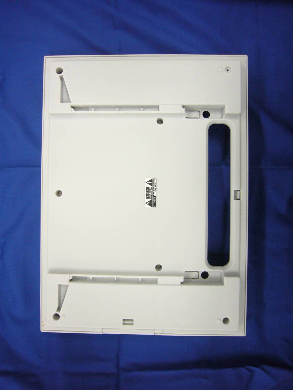
Click to zoom
Application Details
- Equipment Class
- PUB - Part 15 Unlicensed PCS Base Station
- Date of Grant
- Nov 14, 2013
- Application Purpose
- Original Equipment
- Date of Application
- Nov 14, 2013
- Equipment Note
- DECT 6.0 Center Module (with 1 Wireless module)
- Frequency Range
- 1921.53600000 - 1928.44800000
- Country
- United States
Documents & Files
Document Text
Text extracted from the exhibit documents filed with the FCC. Open a document above to read the original.
Users Manual
Center Module Operating Instructions Model No. WX-CC411 WX-CC412 ENGLISH FRANÇAIS ENGLISH VERSION This device complies with Part 15 of FCC Rules and Industry Canada licence-exempt RSS standard(s). Operation is subject to the following two conditions: (1) this device may not cause interference, and (2) this device must accept any interference, including interference that may cause undesired operation of this device. This equipment complies with FCC/IC radiation exposure limits set forth for an uncontrolled environment and meets the FCC radio frequency (RF) Exposure Guidelines in Supplement C to OET65 and RSS-102 of the IC radio frequency (RF) Exposure rules. This equipment should be installed and operated keeping the radiator at least 20cm or more away from person’s body (excluding extremities: hands, wrists, feet and ankles). This transmitter must not be co-located or operated in conjunction with any other antenna or transmitter. Changes or modifications not expressly approved by the party responsible for compliance could void the user’s author ity to operate the equipment. This equipment has been tested and found to comply with the limits for a Class A digital device, pursuant to part 15 of the FCC Rules. These limits are designed to provide reasonable protection against harmful interference when the equipment is operated in a commercial environment. This equipment generates, uses, and can radiate radio frequency energy and, if not installed and used in accordance with the instruction manual, may cause harmful interference to radio communications. Operation of this equipment in a residential area is likely to cause harmful interference in which case the user will be required to correct the interference at his own expense. FEDERAL COMMUNICATIONS COMMISSION INTERFERENCE STATEMENT WARNING: • This apparatus must be earthed. • Apparatus shall be connected to a main socket outlet with a protective earthing connection. • The mains plug or an appliance coupler shall remain readily operable. • To reduce the risk of fire or electric shock, do not expose this apparatus to rain or moisture. • The apparatus should not be exposed to dripping or splashing and that no objects filled with liquids, such as vases, should be placed on the apparatus. • All work related to the installation of this product should be made by qualified service personnel or system installers. • To prevent injury, this apparatus must be securely attached to the floor/wall in accordance with the installation instructions. • The connections should comply with local electrical code. • The risk of hearing impairment due to exposure to excessive sound levels may be reduced by listening at lower volumes and for shorter durations. ・Operating near 2.4 GHz electrical appliances may cause interference. Move away from the electrical appliances. ・This transmitter must not be co-located or operated in conjunction with any other antenna or transmitter. ・MEDICAL: Consult the manufacturer of any personal medical devices, such as pacemakers, to determine if they are adequately shielded from external RF (radio frequency) energy. (The unit operates in the frequency range of 2.412 GHz to 2.462 GHz, and the power output level is 0.1 watts.) Do not use the unit in health care facilities if any regulations posted in the area instruct you not to do so. Hospitals or health care facilities may be using equipment that could be sensitive to external RF (radio frequency) energy. • The installation shall be carried out in accordance with all applicable installation rules. ・To prevent fire or electric shock hazard, do not expose this apparatus to rain or moisture. CAUTION: The FCC ID number for this radio equipment is listed below. FCC ID: ACJ9TAWX-CC411 FCC ID: ACJ9TAWX-CC412 ICES-003 CAN ICES-3(A)/NMB-3(A) CAUTION: • Danger of explosion if battery is incorrectly replaced. Replace only with the same or equivalent type. • These servicing instructions are for use by qualified service personnel only. To reduce the risk of electric shock do not perform any servicing other than that contained in the operating instructions unless you are qualified to do so. ・Any changes or modifications not expressly approved by the party responsible for compliance could void the user’s authority to operate the equipment. ・Shielded (STP) LAN cables must be used with this unit to ensure compliance with EMC standards. RSS-Gen • Under Industry Canada regulations, this radio transmitter may only operate using an antenna of a type and maximum (or lesser) gain approved for the transmitter by Industry Canada. To reduce potential radio interference to other users, the antenna type and its gain should be so chosen that the equivalent isotropically radiated power (e.i.r.p.) is not more than that necessary for successful communication. A lithium-ion battery that is recyclable powers the product you have purchased. Please call 1-800-8-BATTERY for information on how to recycle this battery. For U.S.A. For Canada. For Canada. This product contains a CR Coin Cell Lithium Battery which contains Perchlorate Material – special handling may apply.See www.dtsc.ca/gov/hazardouswaste/perchlorate/ For U.S.A. Important Safety Instructions 1) Read these instructions. 2) Keep these instructions. 3) Heed all warnings. 4) Follow all instructions. 5) Do not use this apparatus near water. 6) Clean only with dry cloth. 7) Do not install near any heat sources such as radiators, heat registers, stoves, or other apparatus (including amplifiers) that produce heat. 8) Do not defeat the safety purpose of the polarized or grounding-type plug. A polarized plug has two blades with one wider than the other. A grounding type plug has two blades and a third grounding prong. The wide blade or the third prong are provided for your safety. If the provided plug does not fit into your outlet, consult an electrician for replacement of the obsolete outlet. 9) Protect the power cord from being walked on or pinched particularly at p…
Text truncated - open the document above for the full version.
Cover Letter(s)
P SSD-13-F042/F043/F044/F045/F046 FCC IDs: ACJ9TAWX-CC411, ACJ9TAWX-CC412, ACJ9TAWX-CT420, ACJ9TAWX-CT450, ACJ9TAWX-CR470 FCC Part 15D – Compliance Information part 15d declarations_draft 13-Mar-2013 page 1 (5) rev.2.0a EUT AND PRODUCT INFORMATION Type of Equipment UPCS (DECT 6.0) Applicant Name Panasonic Corporation of North America Responsible Mfr Name Panasonic System Networks Co., Ltd. Security Systems Business Division Address 1-62, 4-chome, Minoshima, Hakata-ku, Fukuoka 812-8531, Japan Contact Yukio Kaneko Center Module Single Lane Center Module Dual Lane FP Belt Pack All-in-One Headset PP Repeater EUT Type/System FCC ID ACJ9TAWX-CC411 ACJ9TAWX-CC412 ACJ9TAWX-CT420 ACJ9TAWX-CH450 ACJ9TAWX-CR470 Industry Canada ID 216A-WXCC411 216A-WXCC412 216A-WXCT420 216A-WXCH450 216A-WXCR470 Model name WX-CC411 WX-CC412 WX-CT420 WX-CH450 WX-CR470 HW Version XCC411RY1Y XCH450RY1Y PNLB1754ZA SW Version V0.04R00 v0.04R00 4.11 Maximum Antenna Gain 2.14dBi 2.14dBi 1dBi Can the EUT be Initiating Device YES YES YES Does the EUT transmit signaling channels YES YES YES Max number of slots in use simultaneously 5 slots 5 slots 4 slots Test standard: FCC part 15D RSS-213, Issue 2 / RSS-GEN, Issue 3 Frequency Band 1921.536 – 1928.448 MHz Number of RF Channels 5 Frame Period 10 ms Max. Burst length 417us / duplex channel Min. Burst Length 106us / signaling channel Minimum Number of System Channels 60 (12 duplex channels per RF carrier) Supported DECT Slot Types Full Slot Long Slot Operating Mode Simplex Duplex P SSD-13-F042/F043/F044/F045/F046 FCC IDs: ACJ9TAWX-CC411, ACJ9TAWX-CC412, ACJ9TAWX-CT420, ACJ9TAWX-CT450, ACJ9TAWX-CR470 FCC Part 15D – Compliance Information part 15d declarations_draft 13-Mar-2013 page 2 (5) rev.2.0a ANTENNAS Base (FP), Reperter Antenna Type Internal External 1 Pattern Antenna 2 Pattern Antenna 3 4 Does RX and TX use the same antenna(s)? Yes No Handset (PP) Antenna Type Internal External 1 Pattern Antenna 2 Does RX and TX use the same antenna(s)? Yes No ANTENNA DIVERSITY Antenna Diversity Supported TX RX Base (FP), Repeater 1 2 3 4 Handset (PP) 1 2 VOLTAGE AND TEMPERATURE RANGES VOLTAGES Center Module FP Belt Pack All-in-One Headset PP Repeater Nominal Voltage 120V AC DC 3.7V 120V AC Cut-Off Voltage (if applicable) --- DC 3.3V --- POWER SOURCE Type Manufacturer Center Module(FP) Switching Power Supply unit with @ 200 kHz incorporated in the product Model VC30C-24 TDK LAMDA Belt Pack/ Headset (PP) One Lithium ion Battery SANYO Repeater AC Adapter with SPS @ 37 kHz, Model PQLV219(FW) Panasonic Data Connections PSTN Others (please specify) .... P SSD-13-F042/F043/F044/F045/F046 FCC IDs: ACJ9TAWX-CC411, ACJ9TAWX-CC412, ACJ9TAWX-CT420, ACJ9TAWX-CT450, ACJ9TAWX-CR470 FCC Part 15D – Compliance Information part 15d declarations_draft 13-Mar-2013 page 3 (5) rev.2.0a ANCILLARY EQUIPMENT Description Type Manufacturer HOST DEVICE Description Type Manufacturer ADDITIONAL INFORMATION P SSD-13-F042/F043/F044/F045/F046 FCC IDs: ACJ9TAWX-CC411, ACJ9TAWX-CC412, ACJ9TAWX-CT420, ACJ9TAWX-CT450, ACJ9TAWX-CR470 FCC Part 15D – Compliance Information part 15d declarations_draft 13-Mar-2013 page 4 (5) rev.2.0a MANUFACTURERS DECLARATIONS FCC part 15.323 (c)(5) The applicant declares that the system in this application has more than 40 duplex system access channels defined, and that the system is operating in Least Interfered Channel (LIC) mode in accordance with this section. Applicant Agrees Yes No FCC part 15.323 (c)(5) No device or group of co-operating devices located within 1m of each other shall during any frame period occupy more than 6 MHz of aggregate bandwidth, or alternatively, more than one third of the time and spectrum windows defined by the system. Applicant Agrees Yes No FCC part 15.323 (c)(10) The applicant hereby declares that the system in this application does use the criteria of (c)(10) of this section. Applicant Agrees Yes No FCC part 15.323 (c)(11) The applicant hereby declares that system in this application does not use the criteria of (c)(11) of this section. Applicant Agrees Yes No FCC part 15.323 (c)(12) The provisions of (c)(10) or (c)(11) of this section shall not be used to extend the range of spectrum occupied over space or time for the purpose of denying fair access to spectrum to other devices. Applicant Agrees Yes No FCC part 15.307 (b) The Applicant is a participating member of UTAM, Inc. and will provide an affidavit from UTAM, Inc. certifying this. Confirmed By Applicant Yes No ADDITIONAL REMARKS: - DECLARED BY: November 7, 2013 Date Richard Mullen Name (print) Richard Mullen Signature P SSD-13-F042/F043/F044/F045/F046 FCC IDs: ACJ9TAWX-CC411, ACJ9TAWX-CC412, ACJ9TAWX-CT420, ACJ9TAWX-CT450, ACJ9TAWX-CR470 FCC Part 15D – Compliance Information part 15d declarations_draft 13-Mar-2013 page 5 (5) rev.2.0a About this document This document specifies the information that is needed to select the correct testcases and test procedures for testing to FCC Part 15D. The form must be completed by the applicant and submitted to Nemko before testing is started. Preparation of Equipment for Testing Note (a): Number of samples for testing The following samples are needed for FCC 15D testing: RF Conducted Tests: One sample with a 50 ohm antenna connector (preferably SMA Female). Only one antenna connector is needed for these tests even if the equipment has more than one antenna. Monitoring Tests: One sample with 50 ohm antenna connectors fitted to all antennas (preferably SMA female). Additionally we need a companion device that will work together with the EUT, the companion device must also have antenna connectors on all antennas. Radiated Tests: One sample with integral antennas. This sample will be used to measure Antenna Gain, Part 15B and Power-Line Conducted tests. Note (b): Monitoring Tests Monitoring tests are performed by establishing a connection from the handset (or the initiating device) to the base station (or the responding device). Most tests are performed by establishing co…
Text truncated - open the document above for the full version.
Cover Letter(s)
Panasonic Corporation of North America Two Riverfront Plaza, 9 th Floor, Newark, NJ 07102-5490 Tel/Fax: 201-348-7758 / [email protected] Richard Mullen, Group Manager Product Safety and Compliance Department Power of Attorney October 31, 2013 PSSD-13-F046 Federal Communication Commission Equipment Authorization Division / Application Processing Branch 7435 Oakland Mills Road Columbia, Maryland 21046 To whom it may concern; We, the undersigned, Panasonic Corporation of North America, hereby authorizes Nemko AS to act on our behalf in all matters relating to the preparation of TCB Certification application for the below described product in compliance with FCC Part 15D. Any and all acts carried out by Nemko AS on our behalf shall have the same effects as acts of our own for a period of one year from the date of this letter. Type Filing: Original Application for 1.9 GHz DECT Center Module, Model WX-CC411 (Contains 1 Wireless Module) FCC Classification: Isochronous UPCS Base Station (PUB) FCC ID: ACJ9TAWX-CC411 FCC Rule Part: FCC Part 15, Subpart D Frequency Range: 1921.536 ~ 1928.448 Number Channels: 5 RF Channels / 5x12 = 60 TDMA Duplex Channels Type Modulation: Digital (Gaussian Frequency Shift Keying) RF Exposure: Mobile / MPE / Requires minimum spacing distance of 20 cm Responsible Panasonic Corporation of North America Applicant & Grantee: Two Riverfront Plaza, 9 th Floor, Newark, NJ 07102-5490 FRN Number: 0003762242 Sincerely yours, Richard Mullen Richard Mullen Group Manager Panasonic Corporation of North America Cc: Yukio Kaneko / PSN-SSBD / [email protected] Panasonic Corporation of North America Two Riverfront Plaza, 9 th Floor, Newark, NJ 07102-5490 Tel/Fax: 201-348-7758 / [email protected] Richard Mullen, Group Manager Product Safety and Compliance Department Request for Confidentiality October 31, 2013 PSSD-13-F046 Federal Communication Commission Equipment Authorization Division Application Processing Branch 7435 Oakland Mills Road Columbia, Maryland 21046 To whom it may concern; Type Filing: Original Application for 1.9 GHz DECT Center Module, Model WX-CC411 (Contains 1 Wireless Module) FCC Rule Part: FCC Part 15, Subpart D FCC ID: ACJ9TAWX-CC411 In accordance with provisions of Sections 0.457 and 0.459 of the Commission’s Rules and Section 552(b)(4) of the Freedom of Information Act, we request permanent confidentiality for exhibits, which contain: (1) Antenna Construction; (2) Description of Electrical Circuitry; (3) Schematic Diagrams of Base Unit and RF Unit; and (4) Base Unit Block Diagram. The transmitter is not user adjustable and does not have a Tune-Up Procedure. These exhibits contain proprietary, confidential and trade secrets material, which would not be routinely made available for public inspection. In accordance with FCC Public DA 04-1705, we request forty-five day short-term confidentiality, starting from the from the issuance of equipment authorization date, for exhibits, which contain: (1) External Photographs of Base Unit and RF Unit; (2) Internal Photographs of Base Unit and RF Unit; (3) Test Setup Photographs; and (4) User Manual. These exhibits contain pre-market information, which could give our competitors unfair advantage should this information be released before this product is actually introduced into the common marketplace. Sincerely yours, Richard Mullen Richard Mullen Group Manager Panasonic Corporation of North America Product Safety and Compliance Division
Cover Letter(s)
EXHIBIT A STATEMENT OF SECURITY CODE This product has no security codes.
External Photos
EXTERNAL PHOTOGRAPHS WX-CC411 Rear View
ID Label/Location Info
EXHIBIT B MARKINGS Center Module: FCC/IC ID: Below markings is shown on the right side of the unit. FCC 15 statem ent: Below statement is shown on the right side of the unit.
Internal Photos
INTERNAL PHOTOGRAPHS Internal View Main Board RF Portion Main Board Shield Cover removed Back Side
RF Exposure Info
FCC ID: ACJ9TAWX-CC411 MPE Calculation for FCC Uncontrolled Environment Formula from page 18 of OET Bulletin 65, Edition 97 -01 where: S = power density P = power input to the antennaG = power gain of the antenna in the direction of i nterest relative to an isotropic radiator R = distance to the center of radiation of the ante nna Source Based Time Averaged Duty Cycle is 100% in ca lculation below Maximum peak output power at antenna input terminal : 18.80 (dBm) Maximum peak output power at antenna input terminal : 0.076 (W) Maximum antenna gain: 2.14 (dBi) Maximum antenna gain: 1.637 (numeric) Prediction distance: 20 (cm) Prediction frequency: 1925 (MHz) Time Averaged Duty Cycle 100 % MPE limit for uncontrolled exposure at prediction f requency: 10.00 (W/m^2) Power density at prediction frequency: 0.0247 (mW/cm^2) Power density at prediction frequency: 0.247 (W/m^2) Maximum allowable antenna gain: 18.21 (dBi) Margin of Compliance: 16.07 (dB) 2 4 R PG S π =
Test Report
Report No. 245599-1 Template version: B Nemko Norway Nemko AS, Instituttveien 6, P.O. Box 96 Kjeller, 2007 Kjeller, Norway TEL +47 22 96 03 30 FAX +47 22 96 05 50 EMAIL [email protected] ENTERPRISE NUMBER NO974404532 nemko.com/no Test Report Product UPCS Center Module Name and address of the applicant Panasonic Corporation of North America Name and address of the manufacturer Panasonic System Networks Co., Ltd. 1-62, 4-chome, Minoshima, Hakata-ku Fukuoka 812-8531, Japan Model WX-CC411 Rating 120 V AC (Mains Powered) Trademark Panasonic Serial number / Additional information / Tested according to FCC Part 15, subpart D Isochronous UPCS Device, 1920 – 1930 MHz Industry Canada RSS 213, Issue 2 2 GHz License-exempt Personal Communications Service Devices (LE-PCS) Order number 245599 Tested in period 2013.10.10 to 2013.10.24 Issue date 2013.11.05 Name and address of the testing laboratory Instituttveien 6 Kjeller, Norway FCC No: 994405 IC OATS: 2040D-1 TEL: (+47) 22 96 03 30 FAX: (+47) 22 96 05 50 Prepared by [Frode Sveinsen] Approved by [G.Suhanthakumar] This report shall not be reproduced except in full without the written approval of Nemko. Opinions and interpretations expressed within this report are not part of the current accreditation. This report was originally distributed electronically with digital signatures. For more information contact Nemko. TEST REPORT FCC part 15D Report no.: 245599-1 FCC ID: ACJ9TAWX-CC411 Nemko Norway, Instituttveien 6, Kjeller, Norway Page 2 (45) CONTENTS 1 INFORMATION ................................................................................................................................. 3 1.1 Tested Item........................................................................................................................................ 3 1.2 Description of Tested Device ............................................................................................................. 3 1.3 Exposure Evaluation .......................................................................................................................... 3 1.4 Test Environment .............................................................................................................................. 4 1.5 Test Engineer(s) ................................................................................................................................ 4 1.6 Test Equipment ................................................................................................................................. 4 1.7 Other Comments ............................................................................................................................... 4 2 TEST REPORT SUMMARY .............................................................................................................. 5 2.1 General .............................................................................................................................................. 5 2.2 Test Summary ................................................................................................................................... 6 3 TEST RESULTS ................................................................................................................................ 7 3.1 Power Line Conducted Emissions ..................................................................................................... 7 3.2 Coordination with fixed microwave .................................................................................................. 11 3.3 Digital Modulation Techniques ........................................................................................................ 11 3.4 Labeling Requirements ................................................................................................................... 11 3.5 Antenna Requirement...................................................................................................................... 12 3.6 Channel Frequencies ...................................................................................................................... 12 3.7 Automatic Discontinuation of Transmission .................................................................................... 13 3.8 Peak Power Output ......................................................................................................................... 14 3.9 Emission Bandwidth B ..................................................................................................................... 17 3.10 Power Spectral Density ................................................................................................................... 20 3.11 In-Band Unwanted Emissions, Conducted ...................................................................................... 23 3.12 Out-of-band Emissions, Conducted................................................................................................. 25 3.13 Carrier Frequency Stability .............................................................................................................. 29 3.14 Frame Repetition Stability ............................................................................................................... 30 3.15 Frame Period and Jitter ................................................................................................................... 30 3.16 Monitoring Threshold, Least Interfered Channel ............................................................................. 32 3.17 Threshold Monitoring Bandwidth ..................................................................................................... 34 3.18 Reaction Time and Monitoring Interval ............................................................................................ 35 3.19 Time and Spectrum Window Access Procedure ............................................................................. 37 3.20 Acknowledgements …
Text truncated - open the document above for the full version.
Test Setup Photos
FCC ID: ACJ96NWX-CC411 Project no.: 245599 Page 1 of 1 PHOTOS OF TEST SET-UP Power line Conducted Emissions Test
Contact Information
Applicant
Ben Botros(Manager - Regulatory & Compliance)
Test Firm
Nemko ASFrode Sveinsen
Technical Specifications
| # | Rule Parts | Frequency Range | Power Output |
|---|---|---|---|
| 1 | 15D | 1.92 GHz - 1.93 GHz | 76.00 mW |
Other Applications from Panasonic Corporation of North America
ACJ-EAH-A1000
Aug 19, 2026Digital Wireless Stereo Headphones
Equipment Class
DSS - Part 15 Spread Spectrum TransmitterACJ9TGFZVNF3G1
Jun 16, 2026Contactless Smart Card Reader
Equipment Class
DXX - Part 15 Low Power Communication Device Transmitter
ACJ932AM2301
Jan 29, 2025Car AV Control Unit for CDC
Equipment Class
DTS - Digital Transmission SystemACJ96NKX-TGEA60B
Aug 13, 2024DECT Handset
Equipment Class
PUE - Part 15 Unlicensed PCS portable Tx held to earACJ96NKX-TGE630B
Aug 12, 2024DECT Base Unit
Equipment Class
PUB - Part 15 Unlicensed PCS Base Station