ACJ9TGCF-299Panasonic Notebook PC w/ Intel WLAN & Siemens GPRS
Panasonic Corporation of North America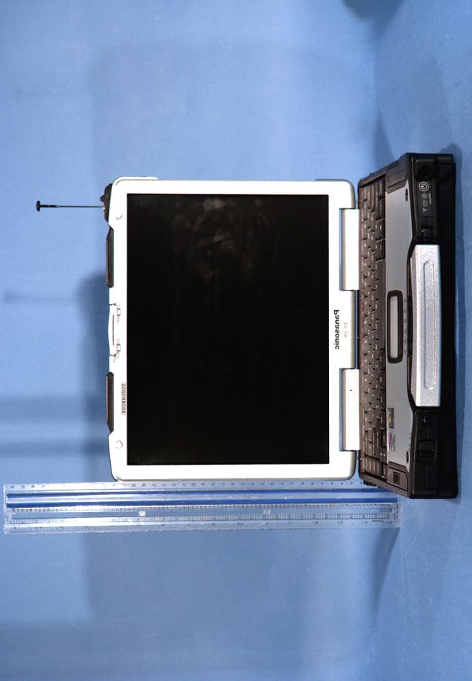
Click to zoom
Application Details
- Equipment Class
- PCB - PCS Licensed Transmitter
- Date of Grant
- Jun 15, 2004
- Application Purpose
- Original Equipment
- Date of Application
- Jun 15, 2004
- Equipment Note
- Panasonic Notebook PC w/ Intel WLAN & Siemens GPRS
- Frequency Range
- 1850.20000000 - 1909.80000000
- Country
- United States
Documents & Files
Document Text
Text extracted from the exhibit documents filed with the FCC. Open a document above to read the original.
Users Manual
OPERATING INSTRUCTIONS Personal Computer Appendix LIMITED USE LICENSE AGREEMENT ..........33 Hard Disk Backup Function .............................35 Hard Disk Data Erase Utility ............................39 Specifications ...................................................40 LIMITED WARRANTY .....................................42 Troubleshooting List of Error Codes ........................................25 Dealing with Problems (Summary).......................26 Reinstalling Software ....................................31 Operation Starting Up/Shutting Down ............................16 Touch Pad (Basic Operation).............................19 Reference Manual .........................................20 Useful Information .........................................21 Getting Started Read Me First..................................................3 Names and Functions of Parts ........................9 First-time Operation ......................................11 Contents [Additional Manual] Reference Manual This manual can be accessed on your computer. Refer to page 20 on how to access the Reference Manual. Reference Manual •Read Me First •Key Combinations Reference Manual •Touch Pad •Touchscreen •Panasonic Hand Writing •Standby/Hibernation Functions •Security Measures •Computing on the Road •Battery Power •Multimedia Pocket •PC Cards •RAM Module •Port Replicator •External Display •Printer •USB Devices •Modem •LAN •Wireless LAN •Hard Disk Drive •Setup Utility •Icon Enlarger Reference Manual •Technical Information •DMI Viewer •List of Error Codes •Dealing with Problems (Advanced) Appendix Getting Started Operation Troubleshooting Model No.CF-29 Series Please read these instructions carefully before using this product and save this manual for future use. XP •LED Indicators 2 Getting Started Introduction Thank you for purchasing the Panasonic computer. Read the operating instructions thoroughly for proper operation of your new computer. Illustrations and Terminology in this Manual Copyright This manual is copyrighted by Matsushita Electric Industrial Co., Ltd. with all rights reserved. No part of this manual may be reproduced in any form without the prior written permission of Matsushita Electric Industrial Co., Ltd. No patent liability is assumed with respect to the use of the information contained herein. ©2004 Matsushita Electric Industrial Co., Ltd. All Rights Reserved. Disclaimer Computer specifications and manuals are subject to change without notice. Matsushita Electric Industrial Co., Ltd. assumes no liability for damage incurred directly or indirectly from errors, omissions or discrepancies between the computer and the manuals. Trademarks Microsoft, Windows and the Windows logo are registered trademarks of Microsoft Corporation of the United States and/or other countries. Intel, Pentium and PROSet are either registered trademarks or trademarks of Intel Corporation. Adobe ® and Acrobat ® are either registered trademarks or trademarks of Adobe Systems Incorporated in the United States and/or other countries. Panasonic is a registered trademark of Matsushita Electric Industrial Co., Ltd. Names of products, brands, etc., appearing in this manual are trademarks or registered trademarks of their respective owner companies. * For the Model No., insert the 12 digit number (for example, CF-29ETKGZKM) located on the bottom of the computer. NOTE:NOTE provides a useful fact or helpful information. CAUTION:CAUTION indicates a condition that may result in minor or moderate injury. Enter :This illustration means to press the [Enter] key. Fn + F5 :This illustration means to press and hold the [Fn] key, then press the [F5] key. [start] - [Run]:This illustration means to click [start], then to click [Run]. For some applications, you may need to double- click. :Where to go for referred information. :This illustration means to refer to the Reference Manual, which is available on your computer. Refer to page 20 on how to access this manual. Some of the illustrations in this manual may differ slightly in shape from the actual items in order to make the explanation easier to understand. The “CD/DVD drive” is a description about drives, such as DVD-ROM, CD-ROM, CD-R/RW, and DVD-ROM & CD-R/ RW drives. This manual covers two types of models, as distinguished by the type of LCD screen (models with touchscreen and models without touchscreen). If the user has logged on without the administrator authority, some functions may not be executable, and some screens may be not displayed as shown in this manual. If this happens, log on with the administrator authority to enable these functions. Confirm the latest information on optional products in catalogs, etc. In this manual, “Microsoft ® Windows ® XP Professional” is indicated as “Windows” or “Windows XP”. Customer's Record Serial No. or Date of Purchase Model No.* Code No. Dealer's Name Dealer's Address 3 Getting Started Read Me First Federal Communications Commission Radio Frequency Interference Statement Note: This equipment has been tested and found to comply with the limits for a Class B digital device, pursuant to Part 15 of the FCC Rules. These limits are designed to provide reasonable protection against harmful interference in a residential installation. This equipment generates, uses and can radiate radio frequency energy and, if not installed and used in accordance with the instructions, may cause harmful interference to radio communications. However, there is no guarantee that interference will not occur in a particular installation. If this equipment does cause harmful interference to radio or television reception, which can be determined by turning the equipment off and on, the user is encouraged to try to correct the interference by one or more of the following measures: Reorient or relocate the receiving antenna. Increase the separation between the equipment and receiver. Connect the equipment into an outlet on a circuit different from that to …
Text truncated - open the document above for the full version.
Users Manual
1 This manual contains supplementary instructions regarding the use of the computer. It ex- plains the cases where the operation of the computer differs from that in the Operating Instructions. Your computer is equipped with GSM/GPRS enabling you to communicate using radio frequencies. Contents Precautions .................................................................. 2 Names and Functions of Parts ................................... 6 Installing/Removing a SIM Card ................................. 7 Installing the Software................................................. 9 Appendix.................................................................... 12 Specifications ............................................................ 13 Supplementary Instructions for GSM/GPRS NOTE:NOTE provides a useful fact or helpful information. CAUTION:CAUTION indicates a condition that may result in minor or moder- ate injury. Windows XP: Information for Microsoft ® Windows ® XP Professional users. Windows 2000: Information for Microsoft ® Windows ® 2000 Professional users. [Start] - [Run]:This illustration means to click [Start], then to click [Run]. (For some applications, you may need to double-click.) About the abbreviations in this manual, refer to the table on page 12. Windows 2000 screens are used in this manual when no specific OS notes are re- quired. Illustrations and Terminology in this Manual 2 The following safety precautions must be observed during all phases of the operation, us- age, service or repair of any Personal Computer or Handheld Computer incorporating GSM/ GPRS modem. Manufacturers of the cellular terminal are advised to convey the following safety information to users and operating personnel and to incorporate these guidelines into all manuals supplied with the product. Failure to comply with these precautions violates safety standards of design, manufacture and intended use of the product. Panasonic as- sumes no liability for customer failure to comply with these precautions. When in a hospital or other health care facility, observe the restrictions on the use of mobiles. Switch Personal Computer or Handheld Computer incorporating GSM/ GPRS modem off, if instructed to do so by the guidelines posted in sensitive areas. Medical equipment may be sensitive to RF energy. The operation of cardiac pacemakers, other implanted medical equipment and hearing aids can be affected by interference from Personal Computer or Handheld Computer incorporating GSM/GPRS modem placed close to the device. If in doubt about potential danger, contact the physician or the manufacturer of the device to verify that the equipment is properly shielded. Pacemaker patients are advised to keep their Personal Computer or Handheld Computer incorporating GSM/GPRS modem away from the pacemaker, while it is on. Switch off Personal Computer or Handheld Computer incorporating GSM/GPRS modem before boarding an aircraft. Make sure it cannot be switched on inadvertently. The operation of wireless appliances in an aircraft is forbidden to prevent interference with communications systems. Failure to observe these instructions may lead to the suspension or denial of cellular services to the offender, legal action, or both. Do not operate Personal Computer or Handheld Computer incorporating GSM/ GPRS modem in the presence of flammable gases or fumes. Switch off the cellu- lar terminal when you are near petrol stations, fuel depots, chemical plants or where blasting operations are in progress. Operation of any electrical equipment in potentially explosive atmospheres can constitute a safety hazard. Your Personal Computer or Handheld Computer incorporating GSM/GPRS mo- dem receives and transmits radio frequency energy while switched on. Remember that interference can occur if it is used close to TV sets, radios, computers or inad- equately shielded equipment. Follow any special regulations and always switch off Personal Computer or Handheld Computer incorporating GSM/GPRS modem wher- ever forbidden, or when you suspect that it may cause interference or danger. Road safety comes first! Do not use a Personal Computer or Handheld Computer incorporating GSM/GPRS modem while driving a vehicle. Do not place the com- puter with GSM/GPRS modem in an area where it could cause personal injury to the driver or passengers. It is recommended to stow the unit in the boot or secure stowage area while driving. Safety Precautions Precautions 3 Do not place the computer with GSM/GPRS modem in an area over an air bag or in the vicinity where an air bag may deploy. Air bags inflate with great force and if the computer with GSM/GPRS modem is placed in the air bag deployment area may be propelled with great force and cause serious injury to occupants of the vehicle. IMPORTANT! Personal Computer or Handheld Computer incorporating GSM/GPRS modem operate using radio signals and cellular networks cannot be guaranteed to con- nect in all conditions. Therefore, you should never rely solely upon any wireless device for essential communications, for example emergency calls. Remember, in order to make or receive calls, Personal Computer or Handheld Computer incorporating GSM/GPRS modem must be switched on and in a ser- vice area with adequate cellular signal strength. Some networks do not allow for emergency calls if certain network services or phone features are in use (e.g. lock functions, fixed dialing etc.). You may need to deactivate those features before you can make an emergency call. Some networks require that a valid SIM card be properly inserted in Personal Computer or Handheld Computer incorporating GSM/GPRS modem. 4 For U.S.A. Federal Communications Commission Radio Frequency Interference Statement Note: This equipment has been tested and found to comply with the limits for a Class B digital device, pursuant to Part 15 of the FCC Rules. These limits are designed to provide reasonable protection against harmful interference in a residential i…
Text truncated - open the document above for the full version.
Cover Letter(s)
August 23, 2004 Federal Communications Commission Equipment Approval Services 7435 Oakland Mills Road Columbia, MD 21046 Attn: Mr. Martin Perrine SUBJECT: Matsushita Electric Industrial Co., Ltd. FCC ID: ACJ9TGCF-299 731 Confirmation No.: TC673719 Correspondence Reference No.: 13488 Request for Tech. Info.: 08/13/04 Dear Martin: Transmitted herewith, on behalf of Matsushita Electric Industrial Co., Ltd. is an amendment provided in response to the request for technical information dated August 13, 2004. 1. Please find that we have revised the FCC Grant to read PCB. 2. The for informational only SAR report has been deleted from the application 3. The grant has been revised to indicate the proper frequency tolerance. We trust this information is sufficient to resolve FCC questions in this application. If you have any further questions, please do not hesitate to contact us. cc: Matsushita Electric Industrial Co., Ltd.
External Photos
Panasonic FCC ID: ACJ9TGCF-299 EUT Photographs © 2004 PCTEST Lab. Toughbook w/ Siemens GPRS Module & WLAN Model: CF-29mk2 Panasonic FCC ID: ACJ9TGCF-299 EUT Photographs © 2004 PCTEST Lab. Toughbook w/ Siemens GPRS Module & WLAN Model: CF-29mk2 Panasonic FCC ID: ACJ9TGCF-299 EUT Photographs © 2004 PCTEST Lab. Toughbook w/ Siemens GPRS Module & WLAN Model: CF-29mk2 Panasonic FCC ID: ACJ9TGCF-299 EUT Photographs © 2004 PCTEST Lab. Toughbook w/ Siemens GPRS Module & WLAN Model: CF-29mk2
External Photos
Panasonic FCC ID: ACJ9TGCF-299 EUT Photographs © 2004 PCTEST Lab. Toughbook w/ Siemens GPRS Module & WLAN Model: CF-29mk2 Panasonic FCC ID: ACJ9TGCF-299 EUT Photographs © 2004 PCTEST Lab. Toughbook w/ Siemens GPRS Module & WLAN Model: CF-29mk2
Internal Photos
6) WLAN exterior photo WLAN Top View WLAN Bottom View 7) WLAN interior photo WLAN inside Top View WLAN inside Bottom View 8) GPRS module position MC46 Module Adapter Position MC46 Module Adapter Slide Position MC46 Module Adapter Top View MC46 Module Adapter Bottom View 9) GPRS Module photo MC46 Module Label Final Design MC46 Module Top View Note: Above Module Label is not final. MC46 Module Interior View MC46 Module Bottom View 10) Antenna position (WLAN) Receive only Antenna Cover Send & Receive Antenna Cover Antenna Cover Open Antenna Cover Open 11) Antenna Magnified photo (WLAN) Top View Receive only Antenna View Send & Receive Antenna View 13) Antenna Position (GPRS) Front View Whip Antenna I/F PWB Whip Antenna Antenna Position (Whip Antenna) 14) Antenna Specification WLAN Send & Receive Antenna: (Inverted F type: 1.86dBi max) WLAN Receive only Antenna: (Inverted F type: 2.86dBi max) GPRS Antenna: (Inverted F type: 2.15dBi max)
RF Exposure Info
Panasonic FCC ID: ACJ9TGCF-299 Notebook EUT Photographs © 2004 PCTEST Lab. PC w/ WLAN & GPRS Module Model: CF-29mk2 Panasonic FCC ID: ACJ9TGCF-299 Notebook EUT Photographs © 2004 PCTEST Lab. PC w/ WLAN & GPRS Module Model: CF-29mk2 Panasonic FCC ID: ACJ9TGCF-295 Notebook EUT Photographs © 2004 PCTEST Lab. PC w/ WLAN, GPRS Module & Bluetooth Model: CF-29mk2
RF Exposure Info
PCTEST MPE REPORT FCC CERTIFICATION REPORT REVIEWED BY: QUALITY MANAGER TEST REPORT S/N: 15.240603344.ACJ TEST DATES: Feb. 19, 2004 EUT TYPE: Notebook PC w/ Intel WLAN & Siemens GPRS FCC ID: ACJ9TGCF-299 PAGE 1 OF 2 © 2004 PCTEST Engineering Laboratory, Inc. RF Exposure Evaluation - Maximum Permissible Exposure (MPE) 1. Introduction This document attempts to prove the safety of radiation generated by RF devices to the human body. The limit for Maximum Permissible Exposure (MPE), specified in FCC 1.1210, is listed below. The power generated by this product is measured by a power meter. Through use of the Friis transmission formula and the maximum gain of the antenna, the distance from the product at which compliance with the MPE limit is achieved may be calculated. Alternatively, near field measurements may be performed to demonstrate compliance at a specific measurement distance. Near field probe: Wandel & Goltermann EMR-20. 2. RF Exposure Limit According to FCC 1.1310: the criteria listed in the following table shall be used to evaluate the environmental impact of human exposure to radio-frequency (RF) radiation as specified in 1.1307(b). LIMITS FOR MAXIMUM PERMISSIBLE EXPOSURE (MPE) Frequency Range (MHz) Electric Field Strength (V/m) Magnetic Field Strength (A/m) Power Density (mW/cm 2 ) Average Time (Minutes) (A) Limits For Occupational / Control Exposures 30-300 61.4 .163 1.0 6 300-1500 ... ... F/300 6 1500-100,000 ... ... 5 6 (B) Limits For General Population / Uncontrolled Exposure 30-300 27.5 .073 .2 30 300-1500 ... ... F/1500 30 1500-100,000 ... ... 1.0 30 F = Frequency in MHz 3. Friis Formula Friis transmission formula: Pd = (P out *G) / (4pr 2 ) Where: Pd = power density in mW/cm 2 (MPE limit) P out = output power to antenna in mW G = gain of antenna in linear scale p = 3.1416 r = distance between observation point and center of the radiator in cm PCTEST MPE REPORT FCC CERTIFICATION REPORT REVIEWED BY: QUALITY MANAGER TEST REPORT S/N: 15.240603344.ACJ TEST DATES: Feb. 19, 2004 EUT TYPE: Notebook PC w/ Intel WLAN & Siemens GPRS FCC ID: ACJ9TGCF-299 PAGE 2 OF 2 © 2004 PCTEST Engineering Laboratory, Inc. Ref.: David K. Cheng, Field and Wave Electromagnetics, Second Edition, Page 640, Eq. (11.133) 4. EUT Operating Condition Software provided by the client enabled the EUT to transmit and receive data at lowest, middle, and highest channels individually. 5. Climate Condition The temperature and relative humidity: 22°C and 78% RH 6. Measurement Results at 20 cm Channel Channel Frequency (MHz) Output Power Power Density (mW/cm 2 ) 190 836.60 1.751 .35 Channel Channel Frequency (MHz) Antenna (mW) Power Density (mW/cm 2 ) 661 1880.00 1.596 .32 7. Conclusion The device meets the mobile 20cm separation distance as specified in Section 2.1091 of the FCC Rules. An appropriate RF exposure compliance statement will be placed in the user’s manual.
Test Report
PCTEST PT. 22/24 REPORT FCC MEASUREMENT REPORT Reviewed By: Quality Manager Test Report S/N: 22/24.240603348.ACJ Test Dates: FEB. 19, 2004 EUT TYPE: Panasonic Toughbook W/ Siemens GPRS Module and INTEL WLAN FCC ID: ACJ9TGCF-299 Page 1 of 25 © 2004 PCTEST ENGINEERING LABORATORY, INC. G PCTEST Engineering Laboratory, Inc. 6660-B Dobbin Road • Columbia, MD 21045 • U.S.A. TEL (410) 290-6652 • FAX (410) 290-6654 http://www.pctestlab.com CERTIFICATE OF COMPLIANCE FCC Part 24 & 22 Certification Matsushita Electric Industrial Co., Ltd. Dates of Tests: February 19, 2004 1006 Oaza Kadoma, Kadoma Test Report S/N: 22/24.240603348.ACJ Osaka, 571 JAPAN Test Site: PCTEST Lab, Columbia MD Project No.: ITPD-04-F029A FCC ID ACJ9TGCF-299 APPLICANT Matsushita Electric Industrial Co., Ltd. Classification: Licensed Portable Transmitter Worn on Body (PCT) FCC Rule Part(s): §24(E), §22H; §2 EUT Type: Panasonic Toughbook CF-29mk2 w/ Siemens MC46 GPRS Module FCC ID: QIPMC46 and Intel Centrino WLAN FCC ID: PD9WM3B2200BG Model: CF-29mk2 Tx Frequency Range: 824.20 – 848.80MHz (GPRS) / 1851.20MHz – 1909.80MHz (PCS GPRS) Rx Frequency Range: 869.20 – 893.80MHz (GPRS) / 1931.20MHz – 1989.80MHz (PCS GPRS) Max. RF Output Power: 1.751 W ERP GPRS (32.433 dBm) / 1.596 W EIRP PCS GPRS (32.021 dBm) Emission Designator(s): 300KGXW (GSM) Test Device Serial No. Identical Prototype [S/N: 3IKYA01097 ] Installed Options: WLAN Bluetooth Dual-Band GPRS Module Other This equipment has been shown to be capable of compliance with the applicable technical standards as indicated in the measurement report and was tested in accordance with the measurement procedures specified in §2.947. This device is approved as a mobile device with respect to RF exposure compliance (see antenna height photo), however, SAR data is included to demonstrate compliance at 1.5 cm spacing or closer. If the EUT contains any additional embedded transmitters, then those transmitters were active during all tests. The remainder of the data is taken from the original modular test report FCC ID: QIPMC46, which is included in this application for reference purposes. I attest to the accuracy of data. All measurements reported herein were performed by me or were made under my supervision and are correct to the best of my knowledge and belief. I assume full responsibility for the completeness of these measurements and vouch for the qualifications of all persons taking them. PCTEST certifies that no party to this application has been denied the FCC benefits pursuant to Section 5301 of the Anti-Drug Abuse Act of 1988, 21 U.S.C. 862. PCTEST PT. 22/24 REPORT FCC MEASUREMENT REPORT Reviewed By: Quality Manager Test Report S/N: 22/24.240603348.ACJ Test Dates: FEB. 19, 2004 EUT TYPE: Panasonic Toughbook W/ Siemens GPRS Module and INTEL WLAN FCC ID: ACJ9TGCF-299 Page 2 of 25 © 2004 PCTEST ENGINEERING LABORATORY, INC. TABLE OF CONTENTS ATTACHMENT A: COVER LETTER(S) ATTACHMENT B: ATTESTATION STATEMENT(S) ATTACHMENT C: TEST REPORT 1.1 SCOPE 3 2.1 INTRODUCTION 4 3.1 INSERTS 5 4.1 DESCRIPTION OF TESTS 6-9 5.1 EFFECTIVE RADIATED POWER OUTPUT 10 6.1 EQUIVALENT ISOTROPIC RADIATED POWER 11 7.1 RADIATED MEASUREMENTS 12-17 8.1 FREQUENCY STABILITY 18-21 9.1 PLOTS OF EMISSIONS 22 10.1 LIST OF TEST EQUIPMENT 23 11.1 SAMPLE CALCULATIONS 24 12.1 CONCLUSION 25 ATTACHMENT D: TEST PLOTS ATTACHMENT E: FCC ID LABEL / LOCATION ATTACHMENT F: TEST SETUP PHOTOGRAPHS ATTACHMENT G: EXTERNAL PHOTOGRAPHS ATTACHMENT H: INTERNAL PHOTOGRAPHS ATTACHMENT I: BLOCK DIAGRAM(S) ATTACHMENT J: SCHEMATIC DIAGRAM(S) ATTACHMENT K: OPERATIONAL / CIRCUIT DESCRIPTION ATTACHMENT L: PARTS LIST/TUNE UP PROCEDURE ATTACHMENT M: USER’S MANUAL ATTACHMENT N: MPE REPORT PCTEST PT. 22/24 REPORT FCC MEASUREMENT REPORT Reviewed By: Quality Manager Test Report S/N: 22/24.240603348.ACJ Test Dates: FEB. 19, 2004 EUT TYPE: Panasonic Toughbook W/ Siemens GPRS Module and INTEL WLAN FCC ID: ACJ9TGCF-299 Page 3 of 25 © 2004 PCTEST ENGINEERING LABORATORY, INC. MEASUREMENT REPORT 1.1 Scope Measurement and determination of electromagnetic emissions (EME) of radio frequency devices including intentional and/or unintentional radiators for compliance with the technical rules and regulations of the Federal Communications Commission. §2.1033 General Information Applicant Name: Matsushita Electric Industrial Co., Ltd. Address: 1006 Oaza Kadoma, Kadoma Oaza, 571 JAPAN • FCC ID: ACJ9TGCF-299 • Quantity: Quantity production is planned • Emission Designators: 300KGXW (GSM) • Tx Freq. Range: 824.20 – 848.80 MHz (GPRS) 1851.20 – 1909.80 MHz (PCS GPRS) • Rx Freq. Range: 869.20 – 893.80 MHz (GPRS) 1931.20 – 1989.80 MHz (PCS GPRS) • Max. Power Rating: 1.751 W ERP GPRS (32.433 dBm) 1.596 W EIRP PCS GPRS (32.021 dBm) • FCC Classification(s): Licensed Portable Transmitter Worn on Body (PCT) • Equipment (EUT) Type: Panasonic Toughbook CF-29mk2 w/ Siemens MC46 GPRS Module FCC ID: QIPMC46 & Intel Centrino WLAN FCC ID: PD9WM3B2200BG • Modulation(s): GPRS • Frequency Tolerance: ± 0.00025% (2.5 ppm) • FCC Rule Part(s): § 24(E), §22H • Dates of Tests: February 19, 2004 • Place of Tests: PCTEST Lab, Columbia, MD U.S.A. • Test Report S/N: 22/24.240603348.ACJ • Project No.: ITPD-04-F029A PCTEST PT. 22/24 REPORT FCC MEASUREMENT REPORT Reviewed By: Quality Manager Test Report S/N: 22/24.240603348.ACJ Test Dates: FEB. 19, 2004 EUT TYPE: Panasonic Toughbook W/ Siemens GPRS Module and INTEL WLAN FCC ID: ACJ9TGCF-299 Page 4 of 25 © 2004 PCTEST ENGINEERING LABORATORY, INC. 2.1 INTRODUCTION These measurement tests were conducted at PCTEST Engineering Laboratory, Inc. facility in New Concept Business Park, Guilford Industrial Park, Columbia, Maryland. The site address is 6660-B Dobbin Road, Columbia, MD 21045. The test site is one of the highest points in the Columbia area with an elevation of 390 feet above mean sea level. The site coordinates are 39° 11'15" N latitude and 76° 49'38" W longitude. The facility is 1.5 miles North of the FCC laboratory, and the ambient signal and amb…
Text truncated - open the document above for the full version.
Test Report
Note: The test results relate only to the individual items which have been tested. This report shall not be reproduced in parts without the written approval of the testing laboratory Applicant:Siemens AG CETECOM - Certification and Testing in Communications GmbH Im Teelbruch 122 D-45219 Essen Germany Telephone: + 49 (0) 20 54 / 95 19 0 Fax: + 49 (0) 2054 / 95 19 20 T E S T R E P O R T No.: 2-20542043b/02 for GPRS/GSM 900/1800/1900 Module MC 45 + DSB 45 + Votronic Handset FCC ID: QIPMC45 TTI-P-G081/94 FCC Registration No. 99538 Test Report 2-20542043b/02, Page 2 of 65 20542043b_02.doc Table of contents 1. SUMMARY OF TEST RESULTS3 2. ADMINISTRATIVE DATA4 2.1. I DENTIFICATION OF THE TESTING LABORATORY 4 2.2. T EST LOCATION 4 2.3. O RGANIZATIONAL ITEMS 4 2.4. A PPLICANT ́ S DETAILS 4 2.5. M ANUFACTURER ́ S DETAILS 4 3. EQUIPMENT UNDER TEST (EUT)5 3.1. EUT: T YPE , S/N ETC . AND SHORT DESCRIPTIONS USED IN THIS TEST REPORT 5 3.2. A UXILIARY E QUIPMENT (AE): T YPE , S/N ETC . AND SHORT DESCRIPTIONS 5 3.3. EUT SET - UPS 6 3.4. EUT OPERATING MODES 6 4. TEST SET-UPS7 4.1. T EST S ET - UP 1 FOR C ONDUCTED MEASUREMENTS 7 4.2. T EST S ET - UP 2 FOR R ADIATED MEASUREMENTS 8 4.3. P ARAMETER SETTINGS ON MOBILE PHONE AND CMU9 5. MEASUREMENTS10 5.1. C ALIBRATION OF ANECHOIC CHAMBER 10 5.2. RF POWER OUTPUT § 2.1046 CONDUCTED 11 5.3. RF POWER OUTPUT § 2.1046 RADIATED 12 5.4. O CCUPIED BANDWIDTH § 2.104913 5.5. S PURIOUS EMISSIONS AT ANTENNA TERMINALS § 2.105117 5.6. F IELD STRENGTH OF SPURIOUS RADIATION § 2.105326 5.7. F REQUENCY STABILITY / TEMPERATURE VARIATION § 2.105550 6. INSTRUMENTS AND ANCILLARY EQUIPMENT „CTC“53 6.1. S INGLE INSTRUMENTS 53 6.2. T EST SYSTEMS 55 7. PHOTOGRAPHS56 7.1. E XTERNAL PHOTOS OF EUT56 7.2. I NTERNAL PHOTOS OF EUT57 7.3. P HOTOS OF TEST SET - UP 59 Test Report 2-20542043b/02, Page 4 of 65 20542043b_02.doc 2. Administrative Data 2.1. Identification of the testing laboratory Company name:CETECOM Certification and Testing in Communications GmbH Address:Im Teelbruch 122 D-45219 Essen - Kettwig Germany Laboratory accreditation:DAR-Registration No.: TTI-P-G081/94 FCC- Registration No.: 99538 Responsible for testing laboratory:Dipl.-Ing. W. Richter Deputies:Dieter Franke Dipl.-Ing. Karin Silberhorn Dipl.-Ing. Heiko Strehlow 2.2. Test location 2.2.1. Test laboratory “CTC” Company name:see chapter 2.1. Identification of the testing laboratory 2.3. Organizational items Reference No.:20542043 Order No.:-- Responsible for test report and project leader:Dipl.-Ing. V. Krueger Receipt of EUT:2002-07-17 Date(s) of test:2002-07-17 – 2002-08-01 Date of report:2002-08-19 Number of report pages:65 Number of diagram pages (annex):no diagrams --------------------------------------------------------------------------------------------------------------------------------------- Version of template: 4.05 2.4. Applicant ́s details Applicant ́s name:Siemens AG Address:Siemensdamm 50 13629 Berlin Germany Contact person:Mr. Hussein Halawi; Tel. +49 30 38630211 2.5. Manufacturer ́s details Manufacturer ́s name:please see Applicant ́s details Address:please see Applicant ́s details Test Report 2-20542043b/02, Page 5 of 65 20542043b_02.doc 3. Equipment under test (EUT) 3.1. EUT: Type, S/N etc. and short descriptions used in this test report short descrip- tion*) EUTType S/N serial number HW hardware status SW software status EUT A GPRS / GSM ModuleMC 4500499941137807 7 B 2.5SW: 34 EUT B Development support box DSB 45# 200B 1.1V 1.0 EUT C Handset VotronicHH-SI-30.3Sample 2V 1.1-- EUT D EUT E EUT F *) EUT short description is used to simplify the identification of the EUT in this test report. Additional Information for EUT A Frequency range:1850.2 – 1909.8 MHz Number of channels:300 Nominal power supply voltage:4,5 V (of module) Power supply range:3,3 – 4,5 V Temperature range:-30°C - +60°C Emission designator:300KGXW Antenna: integral antenna: antenna connector: external antenna Max. stated nominal output power: conducted 30,0 ±2 dBm, radiated 30,0 ±2 dBm EIRP Max. measured output power:conducted 29,7 dBm, radiated 30,6 dBm EIRP 3.2. Auxiliary Equipment (AE): Type, S/N etc. and short descriptions AE short descrip- tion*) Auxiliary EquipmentType S/N serial number HW Hardware status SW software status AE 1 RS 232 cable 1for Com1 - Port--Length=1.81 meter-- AE 2 RS 232 cable 2for Com2 - Port--Length=1.81 meter-- AE 3 AC/DC AdapterMW 1000 GSSample 2Input: 230 V AC, 50 Hz, 28 W Output: 3-6V 9-12 V DC, 1000 mA, 12 VA -- AE 4 GSM Antenna900/ 1800 MHz# 10 dB Gain length=1 meter -- *) AE short description is used to simplify the identification of the auxiliary equipment in this test report. Test Report 2-20542043b/02, Page 6 of 65 20542043b_02.doc 3.3. EUT set-ups EUT set-up no.*) Combination of EUT and AERemarks set. 1EUT A + EUT B + EUT C + AE 1 + AE 2 + AE 3 Set-up for conducted measurements: MC 45 situated outside the DSB45 support-box com-1 cable and com-2 cable connected to DSB-Box but not terminated on the other side (open) set. 2EUT A + EUT B + EUT C + AE 1 + AE 2 + AE 3 + AE 4 Set-up for radiated measurements: MC 45 situated outside the DSB45 support-box com-1 cable and com-2 cable connected to DSB-Box but not terminated on the other side (open) set. 3---- *) EUT set-up no. is used to simplify the identification of the EUT set-up in this test report. 3.4. EUT operating modes EUT operating mode no.*) Description of operating modes Additional information op. 1 IDLE The mobile station is synchronized at the Broadcast Control Channel (BCCH) and listening to the Common Control Channel (CCCH), for details please see chapter: 4.3. Parameter settings on mobile phone and CMU. op. 2 TCH A communication link is established between the mobile station and the test simulator. The transmitter is operated at its maximum rated output power, for details please see chapter: 4.3. Parameter settings on mobile phone and CMU. *) EUT operating mode no. is used to simplify the test report. Test Report 2-20542043b/02, Page 7 of 65 20…
Text truncated - open the document above for the full version.
Test Report
CETECOM ICT Services GmbH Radio Satellite Communication Untertürkheimer Straße 6-10 . D-66117 SaarbrückenTelefon: +49 (0)681 598-9100Telefax: -9075…
Text truncated - open the document above for the full version.
Contact Information
Applicant
Ben Botros(Project Manager)
Technical Contact
PCTEST Engineering Lab., Inc.Randy Ortanez
[email protected]410-290-6652
6660-B Dobbin Road · Columbia, Maryland · United States
Test Firm
PCTEST Engineering Laboratory, Inc.Randy Ortanez
Technical Specifications
| # | Rule Parts | Frequency Range | Power Output | Emission | Tolerance |
|---|---|---|---|---|---|
| 2 | 24E | 1.85 GHz - 1.91 GHz | 1.596 W | 300KGXW | 0.03 ppm |
Other Applications from Panasonic Corporation of North America
ACJ-EAH-A1000
Aug 19, 2026Digital Wireless Stereo Headphones
Equipment Class
DSS - Part 15 Spread Spectrum TransmitterACJ9TGFZVNF3G1
Jun 16, 2026Contactless Smart Card Reader
Equipment Class
DXX - Part 15 Low Power Communication Device Transmitter
ACJ932AM2301
Jan 29, 2025Car AV Control Unit for CDC
Equipment Class
DTS - Digital Transmission SystemACJ96NKX-TGEA60B
Aug 13, 2024DECT Handset
Equipment Class
PUE - Part 15 Unlicensed PCS portable Tx held to earACJ96NKX-TGE630B
Aug 12, 2024DECT Base Unit
Equipment Class
PUB - Part 15 Unlicensed PCS Base Station