ACJ9TGCF-M34Notebook PC with Built In Wireless LAN
Panasonic Corporation of North America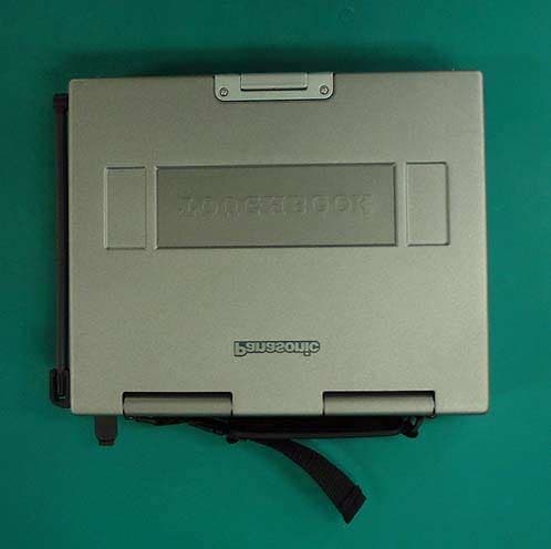
Click to zoom
Application Details
- Equipment Class
- DSS - Part 15 Spread Spectrum Transmitter
- Date of Grant
- Dec 11, 2001
- Application Purpose
- Original Equipment
- Date of Application
- Dec 11, 2001
- Equipment Note
- Notebook PC with Built In Wireless LAN
- Frequency Range
- 2412.00000000 - 2462.00000000
- Country
- United States
Documents & Files
Document Text
Text extracted from the exhibit documents filed with the FCC. Open a document above to read the original.
Users Manual
Supplementary Instructions Personal Computer ® This Supplementary Instructions manual explains how to get started with a wireless LAN and point out cases where the operation of the computer will differ from that in the Operating Instructions and/or Refer- ence Manual. Model No. CF-M34 Series with Wireless LAN 1 Information to the User This product and your Health This product, like other radio devices, emits radio frequency electromagnetic energy. The level of energy emitted by this product however is far much less than the electromagnetic energy emitted by wireless devices like for example mobile phones. Because this product operates within the guidelines found in radio frequency safety standards and recommendations, we believe this product is safe for use by consumers. These standards and recommendations reflect the consensus of the scientific community and result from deliberations of panels and committees of scientists who continually review and interpret the extensive research literature. In some situations or environments, the use of this product may be restricted by the proprietor of the building or responsible representatives of the organization. These situations may for example include: Using this product on board of airplanes, or In any other environment where the risk of interference to other devices or services is perceived or identified as harmful. If you are uncertain of the policy that applies on the use of wireless devices in a specific organization or environment (e.g. airports), you are encouraged to ask for authorization to use this product prior to turning on the product. Regulatory Information We are not responsible for any radio or television interference caused by unauthorized modification of this product. The correc- tion of interference caused by such unauthorized modification will be the responsibility of the user. We and its authorized resellers or distributors are not liable for damage or violation of government regulations that may arise from failing to comply with these guidelines. 2 Federal Communications Commission Radio Frequency Interference Statement Note: This equipment has been tested and found to comply with the limits for a Class B digital device, pursuant to Part 15 of the FCC Rules. These limits are designed to provide reasonable protection against harmful interference in a residential installation. This equipment generates, uses and can radiate radio frequency energy and, if not installed and used in accordance with the instructions, may cause harmful interference to radio communications. However, there is no guarantee that interference will not occur in a particular installation. If this equipment does cause harmful interference to radio or television reception, which can be determined by turning the equipment off and on, the user is encouraged to try to correct the interference by one or more of the following measures: Reorient or relocate the receiving antenna. Increase the separation between the equipment and receiver. Connect the equipment into an outlet on a circuit different from that to which the receiver is connected. Consult the Panasonic Service Center or an experienced radio/TV technician for help. Warning To assure continued compliance, use only shielded interface cables when connecting to a computer or peripheral. Also, any changes or modifications not expressly approved by the party responsible for compliance could void the user’s authority to operate this equipment. This device complies with Part 15 of the FCC Rules. Operation is subject to the following two conditions: (1)This device may not cause harmful interference, and (2)This device must accept any interference received, including interference that may cause undesired operation. Responsible Party: Matsushita Electric Corporation of America One Panasonic Way Secaucus, NJ 07094 Tel No:1-800-LAPTOP-5 (1-800-527-8675) FCC Radiation Exposure Statement: This equipment complies with FCC radiation exposure limits set forth for an uncontrolled environment. This equipment should be installed and operated with minimum distance 20cm between the radiator and your body (excluding extremities: hands, wrists, and feet). For U.S.A. 3 Replace the step 9 for the following.“OPERATING INSTRUCTIONS (page 11)” First-time Operation“OPERATING INSTRUCTIONS (page 9)” If [I do not accept the agreement] is selected, the Windows setup will be aborted. NOTE 9Setup Windows Moving the cursor () or clicking buttons can be performed with the touch pad. Windows 98 1At [Add New Hardware Wizard] of [Texas Instruments PCI-1410 CardBus Controller], select [Next]. 2Select [Search for the best driver for your device.(Recommended)], then select [Next]. 3Select [Specify a location], then select [Next]. 4At [Windows driver file search for the device], select [Next]. 5When [Windows has finished installing the software that your new hardware device requires] is displayed, select [Finish]. 6At [System Settings Change], select [Yes] to restart the computer. 7After restarting, at [Add New Hardware Wizard] of [Lucent Technology-WaveLAN/IEEE], select [Next]. 8Select [Search for the best driver for your device.(Recommended)],then select [Next]. 9Select [Specify a location], then input [C:\util\drivers\wlan] and select [Next]. 10At [Windows driver file search for the device], select [Next]. 11When [Add/Edit Configuration Profile] is displayed, select [Edit]. 12Input [Profile Name], [Network Name] etc. by following the message and select [OK]. If [Version Conflict] is displayed, select [Yes]. 13When [Windows has finished installing the software that your new hardware device requires] is displayed, select [Finish]. 14At [System Settings Change], select [Yes] to restart the computer. 15Select settings for your region and your keyboard layout, then select [Next]. (for U.S.A.: United States 101) 16Enter your name and select [Next]. 17At [Using Your Modem to Connect], select [Skip] . 18At [Cancel Dialing], select [Yes], then select […
Text truncated - open the document above for the full version.
Users Manual
OPERATING INSTRUCTIONS Personal Computer ® Appendix LIMITED USE LICENSE AGREEMENT ........26 Names and Functions of Parts ......................28 Specifications ................................................29 LIMITED WARRANTY ...................................30 Troubleshooting List of Error Codes.........................................19 Dealing with Problems (Summary) .......................21 Reinstalling Software ....................................24 Operation Starting Up/Shutting Down ............................14 Touch Pad (Basic Operation) ...................................17 Reference Manual .........................................18 Getting Started Read Me First..................................................3 First-time Operation ........................................9 Contents [Additional Manual] Reference Manual This manual can be accessed on your computer. Refer to page 18 on how to access the Reference Manual. Reference Manual •Key Combinations Reference Manual •Touch Pad (Advanced) •Touchscreen •Panasonic Hand Writ- ing •Display Rotation Tool •Standby/Hibernation Functions •Security Measures •Computing on the Road •Battery Power •PC Cards •External Display •USB Devices •Modem •LAN •Port Replicator •Accessories •Hard Disk Drive •Setup Utility •LED Indicators Reference Manual •Technical Information •DMI Viewer •List of Error Codes •Dealing with Problems (Advanced) Appendix Getting Started Operation Troubleshooting Model No.CF-M34 Series 2000NT98 Please read these instructions carefully before using this product and save this manual for future use. In this manual, descriptions are given us- ing illustrations not featuring the hand strap for convenience of explanation. 2 Getting Started Introduction Thank you for purchasing the Panasonic computer. Read the operating instructions thoroughly for proper operation of your new computer. Illustrations in this Manual Copyright This manual is copyrighted by Matsushita Electric Industrial Co., Ltd. with all rights reserved. No part of this manual may be reproduced in any form without the prior written permission of Matsushita Electric Industrial Co., Ltd. No patent liability is assumed with respect to the use of the information contained herein. ©2001 Matsushita Electric Industrial Co., Ltd. All Rights Reserved. Disclaimer Computer specifications and manuals are subject to change without notice. Matsushita Electric Industrial Co., Ltd. assumes no liability for damage incurred directly or indirectly from errors, omissions or discrepancies between the computer and the manuals. Trademarks PS/2™ is a trademark of International Business Machines Corporation. Microsoft ® , MS-DOS ® and Windows ® are registered trademarks of Microsoft Corporation of the United States and/or other coun- tries. Intel, Pentium and SpeedStep are registered trademarks of Intel Corporation. Adobe ® and Acrobat ® are either registered trademarks or trademarks of Adobe Systems Incorporated in the United States and/or other countries. Panasonic ® is a registered trademark of Matsushita Electric Industrial Co., Ltd. NOTE:NOTE provides a useful fact or helpful information. CAUTION:CAUTION indicates a condition that may result in minor or moderate injury. WARNING:WARNING indicates a hazard that may result in moderate or serious injury. [Start]-[Shut Down]:This illustration means to click [Start], then to click [Shut Down]. (For some applications, you may need to double-click.) Enter :This illustration means to press the [Enter] key. Fn + F5 :This illustration means to press and hold the [Fn] key, then press the [F5] key. Windows 98 :Information for Microsoft ® Windows ® 98 Second Edition users. Windows 2000 :Information for Microsoft ® Windows ® 2000 Professional users. Windows NT :Information for Microsoft ® Windows NT ® Workstation Version 4.0 users. :Where to go for referred information. :This illustration means to refer to the Reference Manual, which is available on your computer. Refer to page 18 on how to access this manual. * 1 For the Model No., insert the 12 digit number (for example, CF-M34NPFZPM) located on the bottom of the computer. * 2 For Product Key, write down the Product Key shown on the “Certificate of Authenticity” located on the bottom of the computer. Customer's Record Serial No. or Date of Purchase Model No. *1 Code No. Dealer's Name Dealer's Address Product Key *2 3 Getting Started Read Me First Federal Communications Commission Radio Frequency Interference Statement Note: This equipment has been tested and found to comply with the limits for a Class B digital device, pursuant to Part 15 of the FCC Rules. These limits are designed to provide reasonable protection against harmful interference in a residential installation. This equipment generates, uses and can radiate radio frequency energy and, if not installed and used in accordance with the instructions, may cause harmful interference to radio communications. However, there is no guarantee that interference will not occur in a particular installation. If this equipment does cause harmful interference to radio or television reception, which can be determined by turning the equipment off and on, the user is encouraged to try to correct the interference by one or more of the following measures: Reorient or relocate the receiving antenna. Increase the separation between the equipment and receiver. Connect the equipment into an outlet on a circuit different from that to which the receiver is connected. Consult the Panasonic Service Center or an experienced ra- dio/TV technician for help. Warning To assure continued compliance, use only shielded interface cables when connecting to a computer or peripheral. Also, any changes or modifications not expressly approved by the party responsible for compliance could void the user’s authority to operate this equipment. FCC RF Exposure Warning: This computer is provided with PC Card slots that could be used with wireless transmitter(s), which wil…
Text truncated - open the document above for the full version.
Cover Letter(s)
American Telecommunications Certification Body Inc. 6731 Whittier Ave, McLean, VA 22101 December 9, 2001 RE: Matsushita FCC ID: ACJ9TGCF-M34 After a review of the submitted information, I have a few comments on the above referenced Application. 1) Please provide the following additional photographs: top view of LAN module with shields removed & bottom view of LAN module with shields removed. 2) Please upload an exhibit for the operational description. 3) Is the laptop a class A or class B device? Information in the manual states that the device is a class B device. If so, then the labeling information should also show the appropriate DoC labeling. Please correct. 4) The EUT consists of a PC + transmitter integrated together and is subject to the applicable requirements of both. The report provided for certification only covers the transceiver portion of the device. However to meet all the applicable requirements for this device, the laptop should have also been tested (with the transceiver installed) with all ports fully populated (i.e. the additional USB, ethernet, telephone, headphone, microphone, serial, etc.) to meet the DoC requirements as a personal computer. Please confirm that the EUT has been properly evaluated and tested in a fully populated configuration (and with the transceiver installed) or provide a copy of the DoC report. 5) There is approximately 5 dB difference between the peak conducted power (A16) and the peak output radiated power (A9) (measured and corrected using 2.14 dBi). Please explain. 6) The maximum peak radiated power of the fundamental is shown in A9. However, please provide further information to show compliance with the restricted band at the 2.4835 GHz bandedge. Timothy R. Johnson Examining Engineer mailto: [email protected] The items indicated above must be submitted before processing can continue on the above referenced application. Failure to provide the requested information may result in application termination. Correspondence should be considered part of the permanent submission and may be viewed from the Internet after a Grant of Equipment Authorization is issued. Please do not respond to this correspondence using the email reply button. In order for your response to be processed expeditiously, you must submit your documents through the AmericanTCB.com website. Also, please note that partial responses increase processing time and should not be submitted. Any questions about the content of this correspondence should be directed to the sender.
External Photos
<CF-M34 Photo> Front View 1 Front View 2 To p Vi e w Bottom View Magnified the Antenna View
Internal Photos
Inside View 1 Inside View 2 Main PCB Top View Main PCB Bottom View To p C o v e r Vi e w Bottom Cover View Wireless LAN Module Top View Wireless LAN Module Bottom View
Operational Description
Test report FCC ID : ACJ9TGCF-M34 Our reference : 22CE0062-YW Page: 3 of 15 Issued date: December 3, 2001 A-pex International Co., Ltd. YOKOWA LAB. 108 Yokowa-cho, Ise-shi, Mie-ken 516-1106 JAPAN Telephone:int +81 596 39 1485 Facsimile: int +81 596 39 0232 1 GENERAL INFORMATION APPLICANT: Matsushita Electric Industrial Co.,Ltd. AVC Company Personal Computer Division. ADDRESS: 1-10-12 Yaqumohigashi-machi, Moriguchi City Osaka Japan Tel: +81-6-6907-4050 Fax: +81-6-6907-4041 REGULATION(S): FCC Part15 Subpart C, Section 15.247 MODEL NUMBER: CF-M34 SERIAL NUMBER: N/A(Prototype) KIND OF EQUIPMENT: Wireless LAN built in personal computer TESTED DATE: November 19 and 20, 2001 RECEIPT DATE OF SAMPLE : November 19, 2001 REPORT FILE NUMBER: 22CE0062-YW TEST SITE: A-PEX Yokowa No.1 and No.3 Open Test Sites The ORiNOCO Mini PCI radio card is a full-featured, Wi-Fi-compliant wireless device that uses the Mini PCI form factor. The module functions at 2.4 GHz, with a bandwidth of 11 Mbps, and range of up to 1200 feet. It is fully compatible with the entire ORiNOCO line of infrastructure produces for home, office, outdoor and public hot-spot environments. The Mini PCI radio also works with other Wi-Fi-compliant wireless networking systems. Integration into OEM Devices Ideally suited for notebooks, Web pads, Internet appliances and other mobile data applications, the Mini PCI card is only 51 x 60mm in size and weighs 15 grams. The Mini PCI gives manufacturers a great deal of freedom in system design and antenna placement. It can be embedded or designed to be an optional dealer-added feature. ORiNOCO Mini PCI is supported by a complete set of drivers and networking tools to support operating systems including Windows ME, 98, 2000 and Linux. The card is available in two versions, one with 64 WEP encryption and one with 128 bit RC4 encryption. In the automatic mode, the ARS mechanism will select the best possible speed for every data path. This means that the actual speed the mobile clients will use when talking to an Access Point can be different for different stations within one cell. Integration support Lucent provides extensive technical documentation on integration issues like optimal antenna design, customized drivers and management software as well as multi language support for manuals and help files. Echo robustness The delay spread robustness in the IEEE 11 and 5.5 Mbit/s mode is lower than in the IEEE 2 and 1 Mbit/s modes, because delay spread robustness is traded against more sophisticated modulation techniques. Privacy The ORiNOCO Mini PCI Card supports 64 bit WEP as a standard. This means that 64 WEP is used to encrypt the payload data in a message when the end user chooses to run this level of privacy. WEP, which is defined in the IEEE 802.11b standard, uses a 40 bit secret key and a 24 bit Initialization Vector (IV): a 24 bit value unique to a message, which is included in plain text in that message. The IV is included to make sure that two identical plain text messages result in two different encrypted messages. The ORiNOCO/ Mini PCI Card is also released with 128 RC4. This product uses the RC4 encryption algorithm with a 104 bit secret key and a 24 bit IV. Mini PCI Form Factor Radios for Wireless Networking OEMs ORiNOCO TM Mini PCI THE NEW WAVELAN YOUR MOBILE BROADBAND CONNECTION ORiNOCO Mini PCI Card Specifications Frequency Range2400 2462 mHz Number of Selectable Channels11 Modulation TechniqueDirect Sequence Spread Spectrum (CCK, DQPSK, DBPSK) StandardIEEE 802.11b, Mini PCI V1.0 Security64 WEP or 128 RC4 Spreading11 chip Barker sequence Bit Error rateBetter than 10 -5 Media Access ProtocolCSMA/CA (Collision Avoidance) with ACK InterfaceMiniPCI V1.0 PCB Dimension Length:59.75 mm Width: 50.95mm Range (meter/feet)Standard Low SpeedStandard SpeedMedium SpeedHigh Speed (1 Mbit/s)(2 Mbit/s)(5.5 Mbit/s)(11 Mbit/s) Open environment550 m (1750 ft)400 m (1300 ft)270 m (855 ft)160 m (525 ft) Semi-Open environment115 m (375 ft)90 m (300 ft)70 m (230 ft)50 m (165 ft) Closed environment50 m (165 ft)40 m (130 ft)35 m (115 ft)25 m (80 ft) Transmitter output power15 dBm15 dBm15 dBm15 dBm Min. receive level @BER 10^ -5 -94 dBm-91 dBm-87 dBm-82 dBm Delay spread robustness in nanoseconds500 ns400 ns225 ns65 ns Max. Power ConsumptionDoze Mode 16 mA Receive Mode 250mA Transmit Mode 350 mA EnvironmentalThe ORiNOCO Mini PCI Card passes the environmental tests as specified in “Mini PCI Specification, October 1999, Section 5.6 Thermal Guidelines”. Operating temperature0 to 60°C ambient temperature Storage temperature-20 to 75°C ambient temperature Operating humidity95% maximum (non condensing) Storage humidity95% maximum (non condensing) W ired b ackb o n e Basic ORiNOCO Mini PCI Configuration ORiNOCO Mini PCI Card Specifications(continued) Barometric pressure740 to 1050 HPa (storage and operating) Operating System CompatibilityWindows 98, ME and 2000.(NDIS5 Miniport Driver), Linux WHQLDevice WHQL sytem to be certified in co-operation with the OEM manufacturer RegulationsEurope: R&TTE Dir. 1999/5/EC USA: FCC 47 CFR, Part15.247 Canada:ISC RSS139 EnvironmentDelay Spread Office (one room)30 nsec Office40 – 150 nsec Airport120 nsec Warehouse130 nsec Shopping mall90 – 200 nsec Factory300 – 500 nsec Net Throughput11Mb 11Mb11Mb (payload, excluding headers etc)High SpeedMedium SpeedStandard Speed (11 Mbit/s)(5.5 Mbit/s) (2 Mbit/s) Station-to-station (TCP/IP) Peer to Peer5.04 Mbit/s3.44 Mbit/s1.59 Mbit/s Peer to Peer (+WEP128)4.51 Mbit/s3.44 Mbit/s1.59 Mbit/s via AP (both wireless)2.85 Mbit/s via AP (both wireless) (+WEP128)2.62 Mbit/s via AP (one on Ethernet)4.66 Mbit/s via AP (one on Ethernet) (+WEP128)4.11 Mbit/s Frequency Channels Channel Number12 3 4 5 6 78 91011 Channel Frequencies (MHz) 2412 241724222427243224372442 24472452 24572462 For additional information, please contact your Lucent Technologies Sales Representative. You can also visit our web site at http://www.lucent.com or call 1-800-928-3526. ORiNOCO is a t…
Text truncated - open the document above for the full version.
RF Exposure Info
RF Exposure Statement No. : 22CE0062-YW Applicant: Matsushita Electric Industrial Co.,Ltd. Type of Equipment: Wireless LAN builtin Personal Computer Model No.: CF-M34 FCC ID: ACJ9TGCF-M34 A-PEX International Co., Ltd. YOKOWA LAB. 108 Yokowa-cho, Ise-shi, Mie-ken 516-1106 JAPAN Telephone:int +81 596 39 1485 Facsimile: int +81 596 39 0232 Page 1 FCC Radiation Exposure Statement: Matsushita Electric Industrial Co.,Ltd. Model : CF-M34 complies with FCC radiation exposure requirement specified in the FCC Rules 15.247(b)(4). Notice in Installation Manual FCC Radiation Exposure Statement: This equipment complies with FCC radiation exposure limits set forth for an uncontrolled environment. This equipment should installed and operated with minimum distance 20cm between the radiator and your body(excluding extremities : hands, wrists, and feet). RF Exposure Calculations: The following information provides the minimum separation distance for the highest gain antenna provided with the “CF-M34” as calculated from FCC OET 65 Appendix B, Table (B) Limits for General Population / Uncontrolled Exposure. This calculation is based on the highest EIRP possible from the system, considering maximum power and antenna gain, and considering a 1.0m W/cm^2 uncontrolled exposure limit. The Fires formula used was: S = (P * G) / (4* * r^2) or r = (P * G) / (4 * * S) Where S = 1.0 mW/cm^2 for 2400 MHz P = 14.8 mW (Maximum Conducted Power) G = 1.64(Half wave dipole antenna gain : Converted absolute value) r = Minimum safe distance from antenna (cm) For: CF-M34 r = 1.4 cm
Test Report
Test report FCC ID : ACJ9TGCF-M34 Our reference : 22CE0062-YW Page: 2 of 15 Issued date: December 3, 2001 A-pex International Co., Ltd. YOKOWA LAB. 108 Yokowa-cho, Ise-shi, Mie-ken 516-1106 JAPAN Telephone:int +81 596 39 1485 Facsimile: int +81 596 39 0232 Table of Contents Page 1 GENERAL INFORMATION3 1.1 Tested Methodology4 1.2 Test Facility4 2 PRODUCT DESCRIPTION5 2.1Test system Details5 3 SYSTEM TEST CONFIGURATION6 3.1 Justification6 3.2.Configuration of Tested System6 4 MEASUREMENT UNCERTAINTY7 5 TEST INSTRUMENTS8 6 SUMMARY OF TEST9 6.1 §15.207 Conducted Emissions9 6.2 §15.247(a)(2)6dB Bandwidth9 6.3 §15.247(b) Maximum Peak Out Put Power(Radiated and Conducted)10 6.4 §15.247(c) Out of Band Emissions(Radiated)11 6.5 §15.247(c) Out of Band Emissions(Conducted)11 6.6 §15.247(d) Power Density(Conducted)12 6.7 §15.247(e) Processing Gain12 Photographs of test setup 13-14 APPENDIX15 Test dataA1toA64 Test report FCC ID : ACJ9TGCF-M34 Our reference : 22CE0062-YW Page: 3 of 15 Issued date: December 3, 2001 A-pex International Co., Ltd. YOKOWA LAB. 108 Yokowa-cho, Ise-shi, Mie-ken 516-1106 JAPAN Telephone:int +81 596 39 1485 Facsimile: int +81 596 39 0232 1 GENERAL INFORMATION APPLICANT: Matsushita Electric Industrial Co.,Ltd. AVC Company Personal Computer Division. ADDRESS: 1-10-12 Yaqumohigashi-machi, Moriguchi City Osaka Japan Tel: +81-6-6907-4050 Fax: +81-6-6907-4041 REGULATION(S): FCC Part15 Subpart C, Section 15.247 MODEL NUMBER: CF-M34 SERIAL NUMBER: N/A(Prototype) KIND OF EQUIPMENT: Wireless LAN built in personal computer TESTED DATE: November 19 and 20, 2001 RECEIPT DATE OF SAMPLE : November 19, 2001 REPORT FILE NUMBER: 22CE0062-YW TEST SITE: A-PEX Yokowa No.1 and No.3 Open Test Sites Test report FCC ID : ACJ9TGCF-M34 Our reference : 22CE0062-YW Page: 4 of 15 Issued date: December 3, 2001 A-pex International Co., Ltd. YOKOWA LAB. 108 Yokowa-cho, Ise-shi, Mie-ken 516-1106 JAPAN Telephone:int +81 596 39 1485 Facsimile: int +81 596 39 0232 1.1 Tested Methodology The measurement was performed according to the procedures in ANSI C63.4(1992). 1.2 Test Facility The open area site measurement facilities used to collect the radiated data are located at 108, Yokowa-cho, Ise-shi, Mie-ken, 516-1106 Japan. These sites have been fully described in reports submitted to the FCC office. No.1 and No.3 test site has filed to the FCC on September 12, 2000 as number: 90412 and is accepted by Industry Canada on May 01,2001 as number IC2973-1,IC2973-3. Test report FCC ID : ACJ9TGCF-M34 Our reference : 22CE0062-YW Page: 5 of 15 Issued date: December 3, 2001 A-pex International Co., Ltd. YOKOWA LAB. 108 Yokowa-cho, Ise-shi, Mie-ken 516-1106 JAPAN Telephone:int +81 596 39 1485 Facsimile: int +81 596 39 0232 2 PRODUCT DESCRIPTION Matsushita Electric Industrial Co.,Ltd, Model CF-M34 (referred to as the EUT in this report) is a Wireless LAN built in Personal Computer. The specification is as following : Wireless LAN : Direct sequence spread spectrum.(IEEE 802.11b) 2412 through 2462MHz (11channels / each 5MHz wide) Antenna Type:Dipole Antenna Antenna Gain: 2.14dBi Antenna Part No:NIBZBJA00001 I/F:PCMCIA-bus *Fcc Part 15.31(e) The host device CF-M34 provide the LAN Module with stable power supply(DC3.3V), and the LAN module complies power supply regulation. *Fcc Part 15.203 Antenna requirement The wirelss LAN card is installed in the host device and cannot be removed by the user. Connector used between the wireless LAN card and antenna cable is special one (manufacuter's unique specification: TC-1 plug) , and antenna and its cable are solder-mounted so that antenna is unremoved. Due to the above reasons, the wireless LAN card meets the anntena requirements of FCC 15. 203. 2.1 Test System Details Model FCC ID Description (1) Matsushita Electric Industrial Co.,Ltd. ACJ9TGCF-M34 Wireless LAN built in PC M/N: CF-M34 S/N: N/A(Prototype) *FccPart15 Subpart B Class B Digital Device DOC (2)Matsushita Electric Industrial Co.,Ltd.DOC AC Adapter M/N: CF-AA1527C4 S/N: C01091919A Test report FCC ID : ACJ9TGCF-M34 Our reference : 22CE0062-YW Page: 6 of 15 Issued date: December 3, 2001 A-pex International Co., Ltd. YOKOWA LAB. 108 Yokowa-cho, Ise-shi, Mie-ken 516-1106 JAPAN Telephone:int +81 596 39 1485 Facsimile: int +81 596 39 0232 3 SYSTEM TEST CONFIGURATION 3.1 Justification The system was configured in typical fashion (as a customer would normally use it) for testing. Test mode : Data Transmitting mode(bit rate : 11Mbps) Performed the test about channels 1(low), 6(mid) and 11(high) among 11 channels of all Carrier frequencies. Receiving mode 3.2 Configuration of Tested System AC 120V/60Hz Wooden table (1)EUT (2) * Cabling was taken into consideration and test data was taken under worst case conditions. List of cables used No.NameLength (m)ShieldRemark AC Power Cable1.8NPolyvinyl chloride DC Power Cable1.9NPolyvinyl chloride Test report FCC ID : ACJ9TGCF-M34 Our reference : 22CE0062-YW Page: 7 of 15 Issued date: December 3, 2001 A-pex International Co., Ltd. YOKOWA LAB. 108 Yokowa-cho, Ise-shi, Mie-ken 516-1106 JAPAN Telephone:int +81 596 39 1485 Facsimile: int +81 596 39 0232 4 Measurement Uncertainty Conducted Emission Test The measurement uncertainty (with a 95% confidence level) for this test was ±2.0dB. The data listed in this test report may exceed the test limit because it does not have enough margin (more than 2.0dB). The data listed in this test report has enough margin, more than site margin. Radiated Emission Test The measurement uncertainty (with a 95% confidence level) for this test using Biconical antenna is4.4dB. The measurement uncertainty (with a 95% confidence level) for this test using Logperiodic antenna is3.2dB. The measurement uncertainty (with a 95% confidence level) for this test using Horn antenna is5.8dB. The data listed in this test report may exceed the test limit because it does not have enough margin. The data listed in this test report has enough margin, more than site margin. Test report FCC ID …
Text truncated - open the document above for the full version.
Test Setup Photos
Test report FCC ID : ACJ9TGCF-M34 Our reference : 22CE0062-YW Page: 13 of 15 Issued date: December 3, 2001 A-pex International Co., Ltd. YOKOWA LAB. 108 Yokowa-cho, Ise-shi, Mie-ken 516-1106 JAPAN Telephone:int +81 596 39 1485 Facsimile: int +81 596 39 0232 Photographs of test setup(1) Test report FCC ID : ACJ9TGCF-M34 Our reference : 22CE0062-YW Page: 14 of 15 Issued date: December 3, 2001 A-pex International Co., Ltd. YOKOWA LAB. 108 Yokowa-cho, Ise-shi, Mie-ken 516-1106 JAPAN Telephone:int +81 596 39 1485 Facsimile: int +81 596 39 0232 Photographs of test setup(2)
Contact Information
Applicant
Ben Botros(Project Manager)
Technical Contact
A-Pex International Co., Ltd.Naoki Sakamoto
[email protected]+81-596-39-1485
108 Yokowa-cho · Ise-Shi, Mie-ken · Japan
Non-Technical Contact
A-Pex International Co., Ltd.Yukari Ito
[email protected]+81-596-24-6717
Test Firm
UL Japan, Inc.Kazunori Nishimura
Technical Specifications
| # | Rule Parts | Frequency Range | Power Output |
|---|---|---|---|
| 1 | 15C | 2.41 GHz - 2.46 GHz | 14.80 mW |
Other Applications from Panasonic Corporation of North America
ACJ-EAH-A1000
Aug 19, 2026Digital Wireless Stereo Headphones
Equipment Class
DSS - Part 15 Spread Spectrum TransmitterACJ9TGFZVNF3G1
Jun 16, 2026Contactless Smart Card Reader
Equipment Class
DXX - Part 15 Low Power Communication Device Transmitter
ACJ932AM2301
Jan 29, 2025Car AV Control Unit for CDC
Equipment Class
DTS - Digital Transmission SystemACJ96NKX-TGEA60B
Aug 13, 2024DECT Handset
Equipment Class
PUE - Part 15 Unlicensed PCS portable Tx held to earACJ96NKX-TGE630B
Aug 12, 2024DECT Base Unit
Equipment Class
PUB - Part 15 Unlicensed PCS Base Station