ACJ9TGRI15ARFID Module
Panasonic Corporation of North America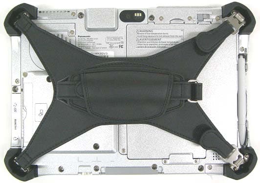
Click to zoom
Application Details
- Equipment Class
- DXX - Part 15 Low Power Communication Device Transmitter
- Date of Grant
- Jun 03, 2015
- Application Purpose
- Original Equipment
- Date of Application
- Jun 03, 2015
- Equipment Note
- RFID Module
- Frequency Range
- 13.56000000 - 13.56000000
- Country
- United States
Documents & Files
Document Text
Text extracted from the exhibit documents filed with the FCC. Open a document above to read the original.
Users Manual
Contents OPERATING INSTRUCTIONS Read Me First Tablet Computer Model No. FZ-G1 series Getting Started First-time Operation ..................................... 17 Read Me First Safety Precautions ......................................... 2 Regulatory Information ................................... 8 A2 A1 Please read these instructions carefully before using this product, and save this manual for future use. Getting Started Read Me First In these instructions, the names and terms are referred as follows. : Conditions that may result in minor or moderate injury. : Useful and helpful information. “Windows ® 8.1 Update Pro 64-bit” as “Windows” or “Windows 8.1” “Windows ® 7 Professional 32-bit Service Pack 1” and “Windows ® 7 Professional 64-bit Ser- vice Pack 1” as “Windows” or “Windows 7” indicates Windows ® 8.1 Operating System. indicates Windows ® 7 Operating System. Refer to the OPERATING INSTRUCTIONS - Basic Guide by downloading from the following URL. URL Ø http://pc-dl.panasonic.co.jp/itn/manual/menu_en.html n Terms and illustrations in these instructions CAUTION NOTE 2 Read Me First Safety Precautions To reduce the risk of injury, loss of life, elec- tric shock, fire, malfunction, and damage to equipment or property, always observe the following safety precautions. Explanation of symbol word panels The following symbol word panels are used to classify and describe the level of hazard, injury, and property damage caused when the denotation is disregarded and improper use is performed. DANGER Denotes a potential hazard that will result in serious injury or death. WARNING Denotes a potential hazard that could result in serious injury or death. CAUTION Denotes a hazard that could result in minor injury. NOTICE Denotes a hazard that could result in prop- erty damage. The following symbols are used to classify and describe the type of instructions to be observed. This symbol is used to alert users to a specific operating procedure that must not be performed. This symbol is used to alert users to a specific operating procedure that must be followed in order to operate the unit safety. DANGER Precautions on the Battery Pack Electrolyte leakage, generation of heat, ignition or rupture of the Battery Pack may result. n Do Not Throw the Battery Pack into a Fire or Expose It to Exces- sive Heat n Do Not Deform, Disassemble, or Modify the Battery Pack n Do Not Short the Positive (+) and Negative (-) Contacts Ö Do not place the battery pack together with articles such as necklaces or hairpins when carry- ing or storing. n Do Not Apply Shocks to the Product by Dropping It, Applying Strong Pressure to It, etc. Ö If this product is subjected to a strong impact, damaged or deformed, stop using it immedi- ately. n Do Not Charge the Battery Using Methods Other Than Those Spec- ified n Do Not Use the Battery Pack with Any Other Product • The battery pack is rechargeable and was intended for the specified product. n Do Not Use This Product with a Battery Pack Other Than the One Specified Ö Use only the specified battery pack with your product. n When the Battery Pack Has De- teriorated, Replace It With a New One Ö Do not continue to use a dam- aged battery pack. n Avoid Extreme Heat (Near the Fire, in Direct Sunlight, for Ex- ample) 3 Read Me First DANGER Precautions on the Built-in Bridge Battery (for disposal) <Only for model with Built-in Bridge Bat- tery> When disposing the battery, generation of heat, ignition or rupture of the Built-in Bridge Battery may result. Handling This Computer n Do Not Disassemble the Com- puter Except When Disposing Handling the Built-in Bridge Battery n Do Not Short the Positive (+) and Negative (-) Contacts n Do Not Throw the Battery into a Fire or Expose It to Excessive Heat n Do Not Apply Shocks to the Built- in Bridge Battery by Dropping It, Applying Strong Pressure to It, etc. n Do Not Charge n Do Not Use n Do Not Deform, Disassemble, or Modify the Built-in Bridge Battery n Avoid Extreme Heat (Near the Fire, in Direct Sunlight, for Ex- ample) WARNING <Only for model with Built-in Bridge Bat- tery> Generation of heat, ignition or rupture of the Built-in Bridge Battery may result. n Do Not Throw This Product Into a Fire or Expose It to Excessive Heat n Do Not Deform, Disassemble, or Modify This Product n Do Not Apply Shocks to the Product by Dropping It, Applying Strong Pressure to It, etc. n Do Not Charge the Battery Using Methods Other Than Those Spec- ified n Avoid Extreme Heat (Near the Fire, In Direct Sunlight, for Ex- ample) n When the Battery Has Deteriorat- ed, Contact Your Technical Sup- port Office to Replace the Battery 4 Read Me First Safety Precautions WARNING Fire or electric shock may result. n Do Not Do Anything That May Damage the AC Cord, the AC Plug, or the AC Adaptor Do not damage or modify the cord, place it near hot tools, bend, twist, or pull it forcefully, place heavy objects on it, or bundle it tightly. Ö Do not continue to use a dam- aged AC cord, AC plug and AC adaptor. • Contact your technical support office for repair. n Do Not Connect the AC Adaptor to a Power Source Other Than a Standard Household AC Outlet Ö Connecting to a DC/AC converter (inverter) may damage the AC adaptor. On an airplane, only connect the AC adaptor/charger to an AC outlet specifically ap- proved for such use. n Do Not Pull or Insert the AC Plug If Your Hands Are Wet n Do Not Disassemble This Prod- uct n Do Not Touch This Product In a Thunderstorm If Connected with the AC Cable or Any Other Cables n If a Malfunction or Trouble Oc- curs, Immediately Stop Use If the Following Malfunction Oc- curs, Immediately Unplug the AC Plug and the Battery Pack • This product is damaged • Foreign object inside this prod- uct • Smoke emitted • Unusual smell emitted • Unusually hot Ö After the above procedure, con- tact your technical support office for repair. n Clean Dust and Other Debris of the AC Plug Regularly • If dust or other debris accumu- lates on the plug, humidity, et…
Text truncated - open the document above for the full version.
Users Manual
2 E Thank you for purchasing this Panasonic product. For optimum performance and safety, please read these instructions carefully. n Terms and illustrations in these instructions NOTE : Useful and helpful information. l Some illustrations are simplified to help your understanding and may look dif- ferent from the actual unit. l Refer for the latest information about optional products to the catalogs, etc. n Disclaimer Computer specification and manuals are subject to change without notice. Panasonic Corporation assumes no liability for damage incurred directly or in- directly from errors, omissions or discrepancies between the computer and the manuals. Introduction 3 E You can read the data from HF-RFID (High-Frequency Radio Frequency Identifi- cation) tags. NOTE l HF-RFID Reader is typically used with specialized applications. For further information, ask the system administrator. A 1 Align the HF-RFID device with the (A) mark and wave the HF-RFID device. NOTE l Operation distance depends on HF-RFID tag. HF-RFID reader×1 (ISO 14443 type-A/B, ISO 15693 Support) Reading HF-RFID Tag Specifications Regulatory Information USA-Federal Communications Commission (FCC) This device complies with Part 15 of the FCC Rules. Operation is subject to the following two conditions: (1) This device may not cause harmful interference, and (2) This device must accept any interference received, including interference that may cause undesired operation. Caution Any changes or modifications not expressly approved by the party responsible for compliance could void the user’s authority to operate the equipment. Labeling System integrators must include the FCC ID on the end product. Canada-Industry Canada (IC) This device complies with Industry Canada licence-exempt RSS standard(s). Operation is subject to the following two conditions: (1) This device may not cause interference, and (2) This device must accept any interference, including interference that may cause undesired operation of the device. Le présent appareil est conforme aux CNR d'Industrie Canada applicables aux appareils radio exempts de licence. L'exploitation est autorisée aux deux conditions suivantes : (1) l'appareil ne doit pas produire de brouillage, et (2) l'utilisateur de l'appareil doit accepter tout brouillage radioélectrique subi, même si le brouillage est susceptible d'en compromettre le fonctionnement. Labeling System integrators must include the IC ID on the end product. Important Notice Panasonic will not sell radio modules to any third party; and will not allow aftermarket installation by any third party or end user. Instead, they will only be installed within Panasonic Notebooks, Laptops, Tablets and Ultra Mobile Toughbook PCs. Panasonic confirms that the provided operating instruction to user will not include any instructions how to add or remove any of the transmitter modules. Printed in Taiwan パナソニック株式会社 ITプロダクツ事業部 〒 570-0021 大阪府守口市八雲東町一丁目 10 番 12 号 © Panasonic Corporation 2013 Panasonic Corporation Osaka, Japan Panasonic System Communications Company of North America Two Riverfront Plaza Newark, NJ 07102 Panasonic Canada Inc. 5770 Ambler Drive, Mississauga, Ontario L4W 2T3 Panasonic Australia Pty. Limited ACN 001 592 187 ABN 83 001 592 187 1 Innovation Road, Macquarie Park NSW 2113 Importer’s name & address pursuant to the EU legislation Panasonic System Communications Company Europe, Panasonic Marketing Europe GmbH Hagenauer Straße 43 65203 Wiesbaden Germany Web Site : http://panasonic.net/
Cover Letter(s)
Panasonic Corporation of North America Two Riverfront Plaza, 9 th Floor, Newark, NJ 07102-5490 Tel/Fax: 201-348-7758 / [email protected] Richard Mullen, Group Manager Product Safety and Compliance Department Agent Authorization Letter May 21, 2015 ITP-15-F020 UL Verification Services, Inc. Certification Division 47173 Benicia Street Fremont, CA 94538, USA Re: Original Limited Single Modular Approval for Panasonic RFID Module, Model RI15A under FCC ID: ACJ9TGRI15A / For Use within Panasonic Personal Computer Model FZ-G1 To whom it may concern: The undersigned hereby authorizes UL Verification Services, Inc. and hereafter referred to as ULVS, to act on our behalf in all manners relating to application for equipment authorization, including signing of all documents relating to these matters. Any and all acts carried out by ULVS on our behalf shall have the same effect as acts of our own. The undersigned hereby certify that I am not subject to a denial of federal benefits, that includes FCC benefits, pursuant to Section 5301 of the Anti-Drug Abuse Act of 1988, 21 U.S.C. 853(a). Further, no party, as defined in 47 CFR 1.2002(b), to the application is subject to denial of federal benefits, that includes FCC benefits. This authorization is valid for one year period from the date of this letter. This application for the subject equipment has not been submitted to another TCB for certification. In authorizing UL VS as our agent, we still recognize that we are responsible to: a) Comply with the relevant provisions of the certification program; b) Make all necessary arrangements for the conduct of the evaluation, including provision for examining documentation and access to all areas, records (including internal audit reports) and personnel for the purposes of evaluation (e.g. testing, inspection, assessment, surveillance, reassessment) and resolution of complaints; c) Make claims regarding certification only in respect of the scope for which certification has been granted; d) Do not use our product certification in such a manner as to bring the Certification Division into disrepute and not make any statement regarding our product certification which the Certification Division may consider misleading or unauthorized; e) Upon suspension or cancellation of certification, discontinue use of all advertising matter that contains any reference thereto and return any certification documents as required by the Certification Division; f) Use certification only to indicate the products are certified as being in conformity with specified standards; g) Endeavor to ensure that no certificate or report nor any part thereof is used in a misleading manner; Panasonic Corporation of North America Two Riverfront Plaza, 9 th Floor, Newark, NJ 07102-5490 Tel/Fax: 201-348-7758 / [email protected] Richard Mullen, Group Manager Product Safety and Compliance Department h) Ensure that any reference to our product certification in communication media such as documents, brochures or advertising, complies with the requirements of the Certification Division; i) Keep a record of all complaints made known to the us relating to the product’s compliance with requirements of the relevant standard and to make these records available to the Certification Division when requested; j) Take appropriate action with respect to such complaints and any deficiencies found in products or services that affect compliance with the requirements for certification; k) Document the actions taken. Authorized by, Richard Mullen Group Manager Panasonic Corporation of North America Product Safety and Compliance Department
Cover Letter(s)
Panasonic Corporation of North America Two Riverfront Plaza, 9 th Floor, Newark, NJ 07102-5490 Tel/Fax: 201-348-7758 / [email protected] Richard Mullen, Group Manager Product Safety and Compliance Department Request for Confidentiality May 21, 2015 ITP-15-F020 UL Verification Services, Inc. Certification Division 47173 Benicia Street Fremont, CA 94538, USA Re: Original Limited Single Modular Approval for Panasonic RFID Module, Model RI15A under FCC ID: ACJ9TGRI15A / For Use within Panasonic Personal Computer Model FZ-G1 To whom it may concern: Pursuant to the provisions of Sections 0.457 and 0.459 of the Commission’s rules (47 CFR §§ 0.457, 0.459), we are requesting the Commission to withhold the following attachments as permanent confidential document from public disclosure. • Theory of Operation • Block diagram • Schematics Above mentioned document contains detailed system and equipment description are considered as proprietary information in operation of the equipment. The public disclosure of above documents might be harmful to our company and would give competitor an unfair advantage in the market. In addition, please be advised that Panasonic Corporation of North America hereby requests the following filed sensitive information to be held under short-term confidential, pursuant to the provisions of Sections 0.457 and 0.459 of the Commission’s Rules and the provisions in FCC Public DA 04-1705. We request temporarily confidentiality of forty-five days, starting from the original issued Certification grant date. • Operating Instructions (Users Manual) • Test Setup Photographs • External and Internal Photographs Panasonic also acknowledges that we will provide appropriate notice to ULVS should either of the following occur. • If we require additional 45 day extension period, we will notify ULVS with a new request letter at least seven days prior to the short-term confidentiality expiration date [Note: up to a maximum of 3 extensions only allowed], or • We will immediately notify ULVS in the event the information regarding the product or the product is made available to the public. ULVS will them release the documents listed above for public disclosure, pursuant to FCC Public Notice DA 04-1705. Thank you for your attention to this matter. Authorized by, Richard Mullen Group Manager Panasonic Corporation of North America Product Safety and Compliance Department
Cover Letter(s)
Applicant/Grantee Panasonic Corporation of North America FCC ID: ACJ9TGRI15A Section 15.212 Modular Transmitters Request for Modular Approval Request for Limited Modular Approval Requirements EUT Conditions Comply (Y/N) Single Modular Approval Requirements 1 The radio elements of the modular transmitter must have their own shielding. The physical crystal and tuning capacitors may be located external to the shielded radio elements. The device does not have Metal shielding to cover RF section. Refer to External Photos. N 2 The modular transmitter must have buffered modulation/data inputs (if such inputs are provided) to ensure that the module will comply with Part 15 requirements under conditions of excessive data rates or over-modulation. All inputs to the device are buffered through logic IC1 inputs. Refer to Schematic Diagram. Y 3 The modular transmitter must have its own power supply regulation. There is no power supply in the module. 3.3V and 5V are fed by the final product. N 4 The modular transmitter must comply with the antenna and transmission system requirements of Sections 15.203, 15.204(b) and 15.204(c). The antenna must either be permanently attached or employ a “unique” antenna coupler (at all connections between the module and the antenna, including the cable). The “professional installation” provision of Section 15.203 is not applicable to modules but can apply to limited modular approvals under paragraph (b) of this section. The device is equipped with the unique antenna connector. Refer to External photos. Y 5 The modular transmitter must be tested in a stand-alone configuration, i.e., the module must not be inside another device during testing for compliance with Part 15 requirements. Unless the transmitter module will be battery powered, it must comply with the AC line conducted requirements found in Section 15.207. AC or DC power lines and data input/output lines connected to the module must not contain ferrites, unless they will be marketed with the module (see Section 15.27(a)). The length of these lines shall be the length typical of actual use or, if that length is unknown, at least 10 centimeters to insure that there is no coupling between the case of the module and supporting equipment. Any accessories, peripherals, or support equipment connected to the module during testing shall be unmodified and commercially available (see Section 15.31(i)). The device was installed into the final product for testing. Refer to setup photos. N 6 The modular transmitter must be equipped with either a permanently affixed label or must be The proposed FCC ID label format is to be placed on the module. If Y capable of electronically displaying its FCC identification number. (A) If using a permanently affixed label, the modular transmitter must be labeled with its own FCC identification number, and, if the FCC identification number is not visible when the module is installed inside another device, then the outside of the device into which the module is installed must also display a label referring to the enclosed module. This exterior label can use wording such as the following: “Contains Transmitter Module FCC ID: XYZMODEL1” or “Contains FCC ID: XYZMODEL1.” Any similar wording that expresses the same meaning may be used. The Grantee may either provide such a label, an example of which must be included in the application for equipment authorization, or, must provide adequate instructions along with the module which explain this requirement. In the latter case, a copy of these instructions must be included in the application for equipment authorization. (B) If the modular transmitter uses an electronic display of the FCC identification number, the information must be readily accessible and visible on the modular transmitter or on the device in which it is installed. If the module is installed inside another device, then the outside of the device into which the module is installed must display a label referring to the enclosed module. This exterior label can use wording such as the following: “Contains FCC certified transmitter module(s).” Any similar wording that expresses the same meaning may be used. The user manual must include instructions on how to access the electronic display. A copy of these instructions must be included in the application for equipment authorization. FCC ID is not visible when the module is installed into the system, “Contains FCC ID: ACJ9TGRI15A” shall be placed on the outside of final host system. 7 The modular transmitter must comply with any specific rules or operating requirements that ordinarily apply to a complete transmitter and the manufacturer must provide adequate instructions along with the module to explain any such requirements. A copy of these instructions must be included in the application for equipment authorization. Refer to “User’s Guide” Exhibit Y 8 The modular transmitter must comply with any applicable RF exposure requirements in its final configuration. The device complies with RF exposure compliance requirement Y A limited modular approval may be granted for single or split modular transmitters that do not comply with all of the above requirements, e.g., shielding, minimum signaling amplitude, buffered modulation/data inputs, or power supply regulation, if the manufacturer can demonstrate by alternative means in the application for equipment authorization that the modular transmitter meets all the applicable Part 15 requirements under the operating conditions in which the transmitter will be used. Limited modular approval also may be granted in those instances where compliance with RF exposure rules is demonstrated only for particular product configurations. The applicant for certification must state how control of the end product into which the module will be installed will be maintained such that full compliance of the end product is always ensured.
External Photos
FCC ID:ACJ9TGRI15A/IC:216A-CFRI15A FZ-G1 External Photos 1/3 1) External photos 1-1) Front 1-2) Back 1 FCC ID:ACJ9TGRI15A/IC:216A-CFRI15A FZ-G1 External Photos 2/3 1-3) Back 2 FCC ID:ACJ9TGRI15A/IC:216A-CFRI15A FZ-G1 External Photos 3/3 1-4) Edge1 1-5) Edge2 1-6) Edge3 1-7) Edge4
External Photos
FCC ID:ACJ9TGRI15A/IC:216A-CFRI15A FZ-G1 External Photos 1/1 HF-RFID photos <Front side> <Back side>
ID Label/Location Info
FCC ID:ACJ9TGRI15A/IC:216A-CFRI15A Label 1/2 1. Label for FZ-G1 1-1. FCC ID “ACJ9TGRI15A” Label This PC contains/Ce PC contient; FCC ID : ACJ9TGRI15A IC : 216A-CFRI15A FCC ID:ACJ9TGRI15A/IC:216A-CFRI15A Label 2/2 2. Label location Equipment of FZ-G1 Bottom side Label for FZ-G1 FCC ID / IC ID
Internal Photos
FCC ID:ACJ9TGRI15A/IC:216A-CFRI15A FZ-G1 internal Photos 1/2 Host PC: Model FZ-G1 Appearance of back side For the photos, a hand strap is removed. HF-RFID Module FCC ID:ACJ9TGRI15A/IC:216A-CFRI15A FZ-G1 internal Photos 2/2 The module cover was removed. This is a HF-RFID module and antenna.
Internal Photos
FCC ID:ACJ9TGRI15A/IC:216A-CFRI15A FZ-G1 internal Photos 1/1 HF-RFID module <Front side> <Back side> HF-RFID Module Antenna
Test Report
NVLAP LAB CODE: 200572-0 This laboratory is accredited by the NVLAP LAB CODE 200572-0, U.S.A. The tests reported herein have been performed in accordance with its terms of accreditation. *As for the range of Accreditation in NVLAP, you may refer to the WEB address, http://www.ul.com/japan/jpn/pages/services/emc/abo ut/mark1/index.jsp#nvlap FCC CFR47 PART 15 SUBPART C CERTIFICATION TEST REPORT FOR RFID MODULE MODEL NUMBER: RI15A FCC ID: ACJ9TGRI15A REPORT NUMBER: 10773679H-A-R1 ISSUE DATE: June 3, 2015 Prepared for PANASONIC CORPORATION OF NORTH AMERICA ONE PANASONIC WAY, 4B-8 SECAUCUS, NEW JERSEY, 07094, USA Prepared by UL Japan, Inc. Ise EMC Lab. 4383-326 Asama-cho, Ise-shi Mie-ken 516-0021 JAPAN TEL: +81 596 24 8999 FAX: +81 596 24 8124 REPORT NO: 10773679H-A-R1 DATE: June 3, 2015 FCC ID: ACJ9TGRI15A Page 2 of 39 UL Japan, Inc. Ise EMC Lab. 4383-326 Asama-cho, Ise-shi, Mie-ken 516-0021 JAPAN TEL: +81 596 24 8999 FAX: +81 596 24 8124 This report shall not be reproduced except in full, without the written approval of UL Japan Revision History Rev. Issue Date Revisions Revised By -- 06/02/2015 Initial Issue T. Hatakeda 1 06/03/2015 1. Addition of 20dB BANDWIDTH test data *This report is a revised version of 10773679H-A, which is replaced with this report. T. Hatakeda REPORT NO: 10773679H-A-R1 DATE: June 3, 2015 FCC ID: ACJ9TGRI15A Page 3 of 39 UL Japan, Inc. Ise EMC Lab. 4383-326 Asama-cho, Ise-shi, Mie-ken 516-0021 JAPAN TEL: +81 596 24 8999 FAX: +81 596 24 8124 This report shall not be reproduced except in full, without the written approval of UL Japan TABLE OF CONTENTS 1. ATTESTATION OF TEST RESULTS ..................................................................................... 4 2. TEST METHODOLOGY .......................................................................................................... 5 3. FACILITIES AND ACCREDITATION ..................................................................................... 5 4. CALIBRATION AND UNCERTAINTY .................................................................................... 5 4.1. MEASURING INSTRUMENT CALIBRATION .................................................................. 5 4.2. SAMPLE CALCULATION ................................................................................................. 5 4.3. MEASUREMENT UNCERTAINTY ................................................................................... 6 5. TEST PROCEDURE AND RESULTS .................................................................................... 7 6. EQUIPMENT UNDER TEST ................................................................................................... 8 6.1. DESCRIPTION OF EUT ................................................................................................... 8 6.2. MAXIMUM TRANSMITTER FIELD STRENGTH ............................................................. 8 6.3. DESCRIPTION OF AVAILABLE ANTENNAS .................................................................. 8 6.4. SOFTWARE AND FIRMWARE ........................................................................................ 8 6.5. WORST-CASE CONFIGURATION AND MODE ............................................................. 8 6.6. MODIFICATIONS ............................................................................................................. 8 6.7. DESCRIPTION OF TEST SETUP .................................................................................... 9 7. TEST AND MEASUREMENT EQUIPMENT ........................................................................ 11 8. RADIATED EMISSION TEST RESULTS ............................................................................. 12 8.1. LIMITS AND PROCEDURE ........................................................................................... 12 8.2. FUNDAMENTAL EMISSION .......................................................................................... 14 8.3. SPURIOUS EMISSIONS (0.15 – 30 MHz) ..................................................................... 19 8.4. SPURIOUS EMISSION 30 TO 1000 MHz ..................................................................... 23 9. AC MAINS LINE CONDUCTED EMISSIONS ...................................................................... 27 10. FREQUENCY STABILITY ................................................................................................. 32 11. 20dB BANDWIDTH ........................................................................................................... 34 12. SETUP PHOTOS ............................................................................................................... 37 REPORT NO: 10773679H-A-R1 DATE: June 3, 2015 FCC ID: ACJ9TGRI15A Page 4 of 39 UL Japan, Inc. Ise EMC Lab. 4383-326 Asama-cho, Ise-shi, Mie-ken 516-0021 JAPAN TEL: +81 596 24 8999 FAX: +81 596 24 8124 This report shall not be reproduced except in full, without the written approval of UL Japan 1. ATTESTATION OF TEST RESULTS COMPANY NAME: PANASONIC CORPORATION OF NORTH AMERICA ONE PANASONIC WAY, 4B-8 SECAUCUS, NEW JERSEY, 07094, USA EUT DESCRIPTION: RFID MODULE MODEL: RI15A SERIAL NUMBER: 4JTSA00145 DATE TESTED: May 21 and 22, 2015 APPLICABLE STANDARDS STANDARD TEST RESULTS FCC PART 15 SUBPART C Pass UL Japan, Inc. tested the above equipment in accordance with the requirements set forth in the above standards. All indications of Pass/Fail in this report are opinions expressed by UL Japan, Inc. based on interpretations and/or observations of test results. Measurement Uncertainties were not taken into account and are published for informational purposes only. The test results show that the equipment tested is capable of demonstrating compliance with the requirements as documented in this report. Note: The results documented in this report apply only to the tested sample, under the conditions and modes of operation as described herein. This document may not be altered or revised in any way unless done so by UL Japan…
Text truncated - open the document above for the full version.
Test Setup Photos
REPORT NO: 10773679H-A-R1 DATE: June 3, 2015 FCC ID: ACJ9TGRI15A Page 37 of 39 UL Japan, Inc. Ise EMC Lab. 4383-326 Asama-cho, Ise-shi, Mie-ken 516-0021 JAPAN TEL: +81 596 24 8999 FAX: +81 596 24 8124 This report shall not be reproduced except in full, without the written approval of UL Japan 12. SETUP PHOTOS RADIATED EMISSION Photo 1 Photo 2 REPORT NO: 10773679H-A-R1 DATE: June 3, 2015 FCC ID: ACJ9TGRI15A Page 38 of 39 UL Japan, Inc. Ise EMC Lab. 4383-326 Asama-cho, Ise-shi, Mie-ken 516-0021 JAPAN TEL: +81 596 24 8999 FAX: +81 596 24 8124 This report shall not be reproduced except in full, without the written approval of UL Japan Worst Case Position Below 30MHz(Y-axis) Above 30MHz(Horizontal: Y-axis/ Vertical: Y-axis) X-axis Y-axis Z-axis REPORT NO: 10773679H-A-R1 DATE: June 3, 2015 FCC ID: ACJ9TGRI15A Page 39 of 39 UL Japan, Inc. Ise EMC Lab. 4383-326 Asama-cho, Ise-shi, Mie-ken 516-0021 JAPAN TEL: +81 596 24 8999 FAX: +81 596 24 8124 This report shall not be reproduced except in full, without the written approval of UL Japan AC MAINS LINE CONDUCTED EMISSION Photo 1 Photo 2 END OF REPORT
Contact Information
Applicant
Ben Botros(Project Manager)
Test Firm
UL Japan, IncMitsuru Fujimura
Technical Specifications
| # | Rule Parts | Frequency Range | Power Output |
|---|---|---|---|
| 1 | 15C | 13.56 MHz - 13.56 MHz | - |
Other Applications from Panasonic Corporation of North America
ACJ-EAH-A1000
Aug 19, 2026Digital Wireless Stereo Headphones
Equipment Class
DSS - Part 15 Spread Spectrum TransmitterACJ9TGFZVNF3G1
Jun 16, 2026Contactless Smart Card Reader
Equipment Class
DXX - Part 15 Low Power Communication Device Transmitter
ACJ932AM2301
Jan 29, 2025Car AV Control Unit for CDC
Equipment Class
DTS - Digital Transmission SystemACJ96NKX-TGEA60B
Aug 13, 2024DECT Handset
Equipment Class
PUE - Part 15 Unlicensed PCS portable Tx held to earACJ96NKX-TGE630B
Aug 12, 2024DECT Base Unit
Equipment Class
PUB - Part 15 Unlicensed PCS Base Station