ACJ9TGWLM-1
Panasonic Corporation of North America
Click to zoom
Application Details
- Equipment Class
- DSS - Part 15 Spread Spectrum Transmitter
- Date of Grant
- Nov 27, 2001
- Application Purpose
- Original Equipment
- Date of Application
- Sep 10, 2001
- Frequency Range
- 2412.00000000 - 2462.00000000
- Country
- United States
Documents & Files
Document Text
Text extracted from the exhibit documents filed with the FCC. Open a document above to read the original.
Users Manual
18 Getting Started 3Select [AdHoc]. The following screen is displayed. <Wireless display screen> Change setting on host PC to the following value, reboot the host PC, then select "Connect" below. Wireless LAN card Network Type : AdHoc SSID : cfvdw07-43411 Encryption : disable TCP/IP IP Address : 10.57.148.205 NetMask : 255.0.0.0 MeiWDS Password : wdsp Connect Cancel First-time Operation CAUTION Do not select [Connect] until step 9 is completed. This screen is a sample. 11Setup the wireless display 1Set the battery pack in the wireless display. 2Connect the wireless display to a power outlet and turn the wireless display on. The following screen is displayed. <Wireless display screen> Select network type. AdHocInfrastructureCancel To the computer ( Page 14) Be sure to insert the battery pack as illustrated. CAUTION Ta b connector 19 Getting Started 4Select on the taskbar of the external display, then select [Configuration] The following screen is displayed. <External display screen> Match the settings of the computer with the information displayed on <Wireless display screen> of the step 3 . If there is no input from a key or an external mouse for a certain interval of time, the power to the wireless display may be turned off automatically. In this case, turn on the wireless display and then start the procedure from step 3 . NOTE 5Select [Apply Changes], then select [OK]. 6Select [Start] - [Settings] - [Control Panel] - [Network] - [TCP/IP PRISM2 IEEE 802.11 PC CARD Adapter] - [Properties] - [IP Address]. The following screen is displayed. This screen is a sample. <External display screen> Match the settings of the computer with the information displayed on <Wireless display screen> of the step 3 . 7Select [OK], then select [OK]. 8Restart the computer. 9Select [Connect] on <Wireless display screen> of the step 3 . This screen is a sample. Set to [802.11.AdHoc]. 20 Getting Started 14Set the necessary items, select [Next]. The following screen is displayed. <Step 2> 13Input [wdsp], then select [OK]. The following screen is displayed. <Step 1> First-time Operation 12Select on the taskbar, select [Run Setup Utility]. The following screen is displayed. <When using except default settings> <External display screen> 11Input [wdsp], then select [OK]. The wireless display can be used. This screen is a sample. 10Select on the taskbar, select [Password]: The following screen is displayed. This screen is a sample. 21 Getting Started 15Select on the taskbar, set the parameters in [Wireless LAN]. Ignore although you attempt a reconnection on the wireless display side and are unsuccessful. 16Select on the taskbar, select [Password]. Set the password by following <Step 2> screen. 17Select [Next] at the <Step 2> screen. The following screen is displayed. 18Select [Start] - [Settings] - [Control Panel] - [Network] - [TCP/IP PRISM2 IEEE 802.11 PC CARD Adapter], set the parameters by following the above <Step 3> screen, then select [OK]. Ignore although you attempt a reconnection on the wireless display side and are unsuccessful. 19Restart the computer. <Step 3> This screen is a sample.
Block Diagram
WMAC:HFA384 PCMCIA Bus FLASH128k x 8 SRAM128k x 8 Xtal44MHz D A D A A D A D I I Q Q VCO748 MHz PLL SAW374MHz VCO2038 – 2110MHz PLL Antenna TX/RX PAw/detector: RF/IFconverter: 2400– 2483.5MHz LN IF I/ Q MDO/DEMOD:HFA3783 Base bandprocesor: Block Diagram – Panasonic Wireless LAN radio module(WLM 1) 1 2 3 4 5 6 7 8 9 10 11 12 13 14 15 16 17 18
ID Label/Location Info
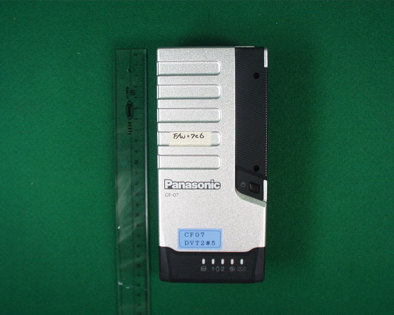
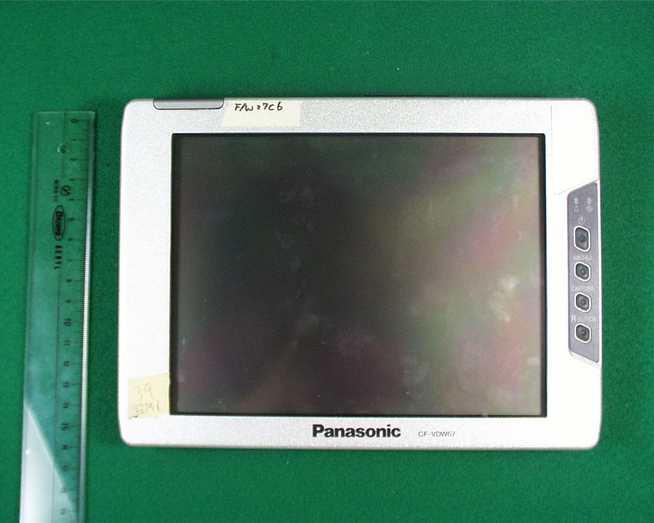
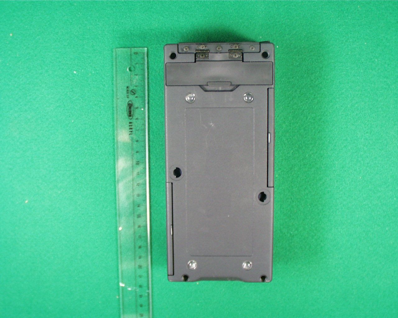
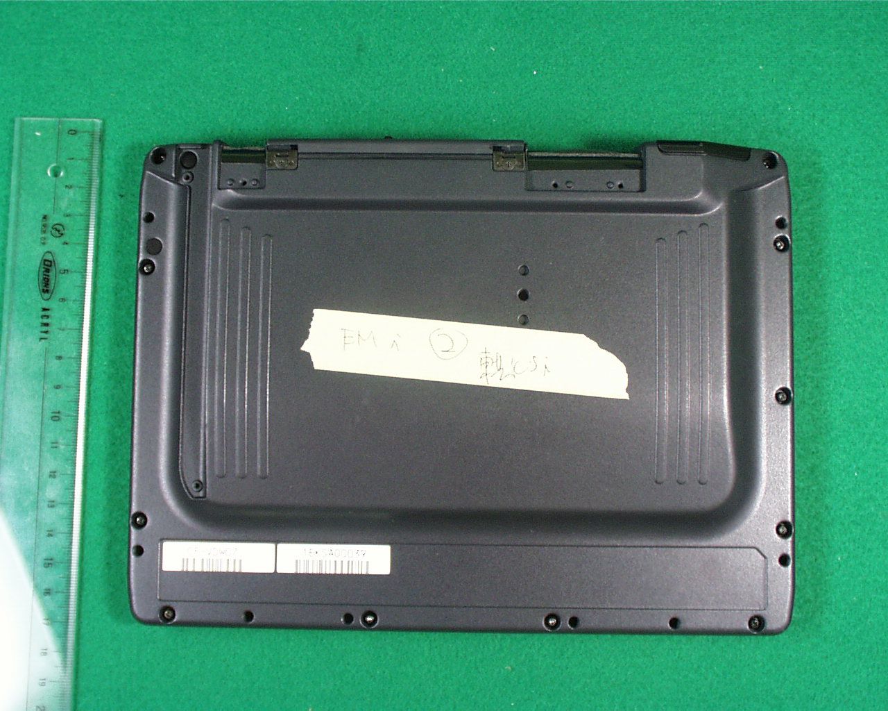
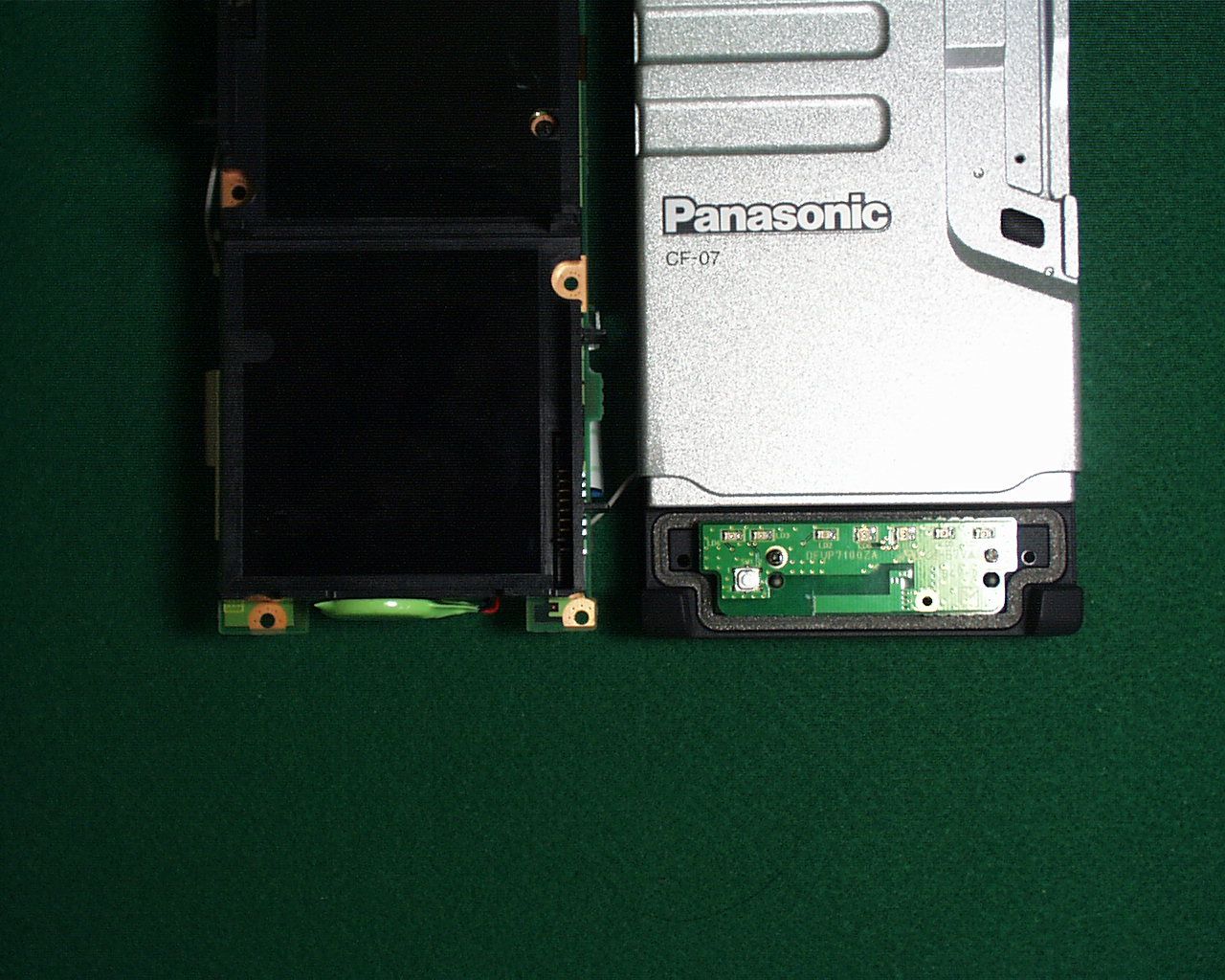
<CF-07 Photo> Front view Rear view CF-07 Rating Plate Position *Refer to the Attachment 1 for CF-07 Rating Plate. (“Contains FCC ID:ACJ9TGWLM-1” is indicated on the Rating Plate) <CF-VDW07 Photo> Front View Rear View CF-VDW07 Rating Plate Position *Refer to the Attachment 2 for CF-VDW07 Rating Plate. (“Contains FCC ID:ACJ9TGWLM-1” is indicated on the Rating Plate)
ID Label/Location Info
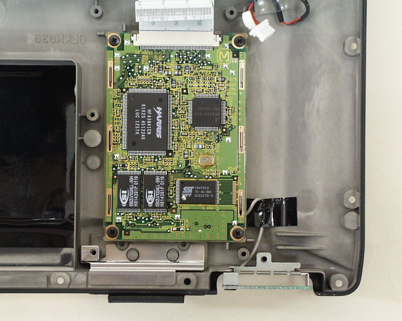
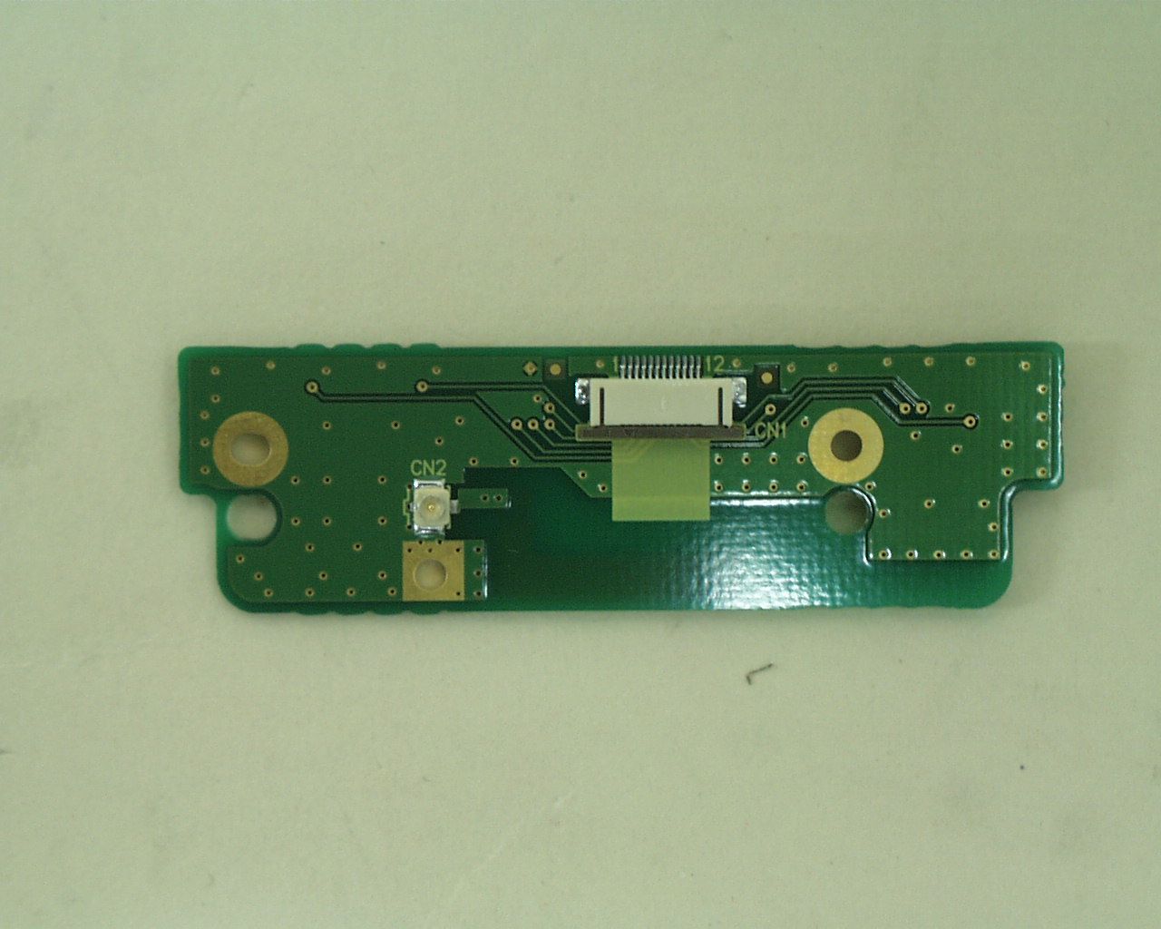
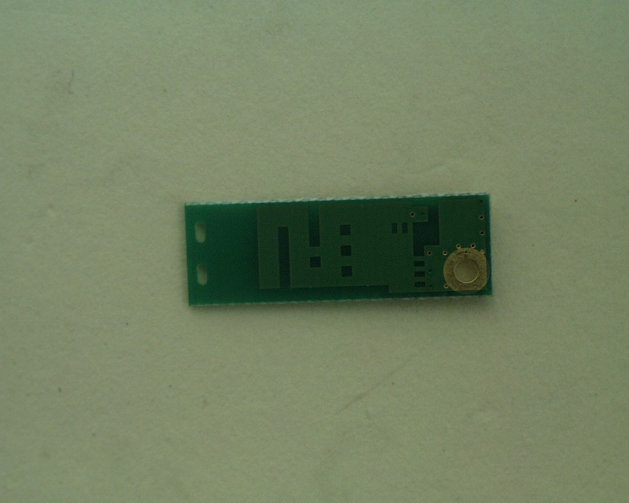
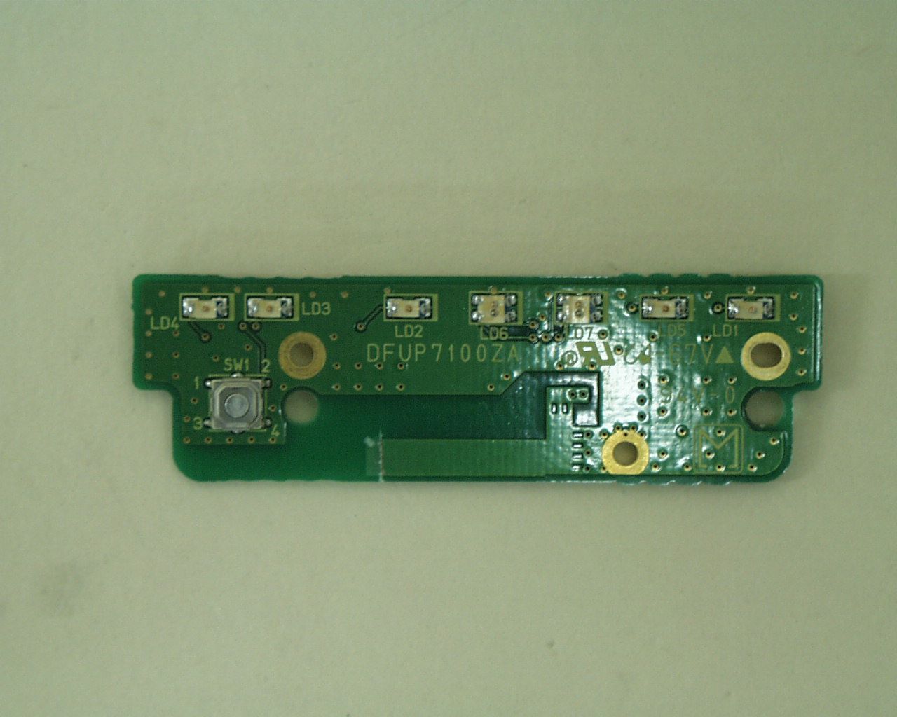
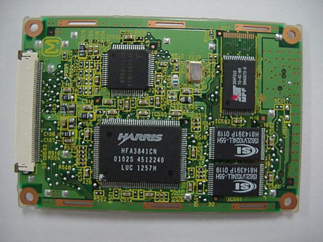
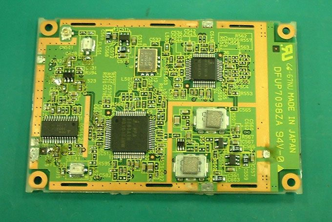
<WLM-1 photo> 1) Shield surface 2) Component surface WLM-1 Rating Plate (include FCC ID) (include Canada 210 Certification Number)
Operational Description
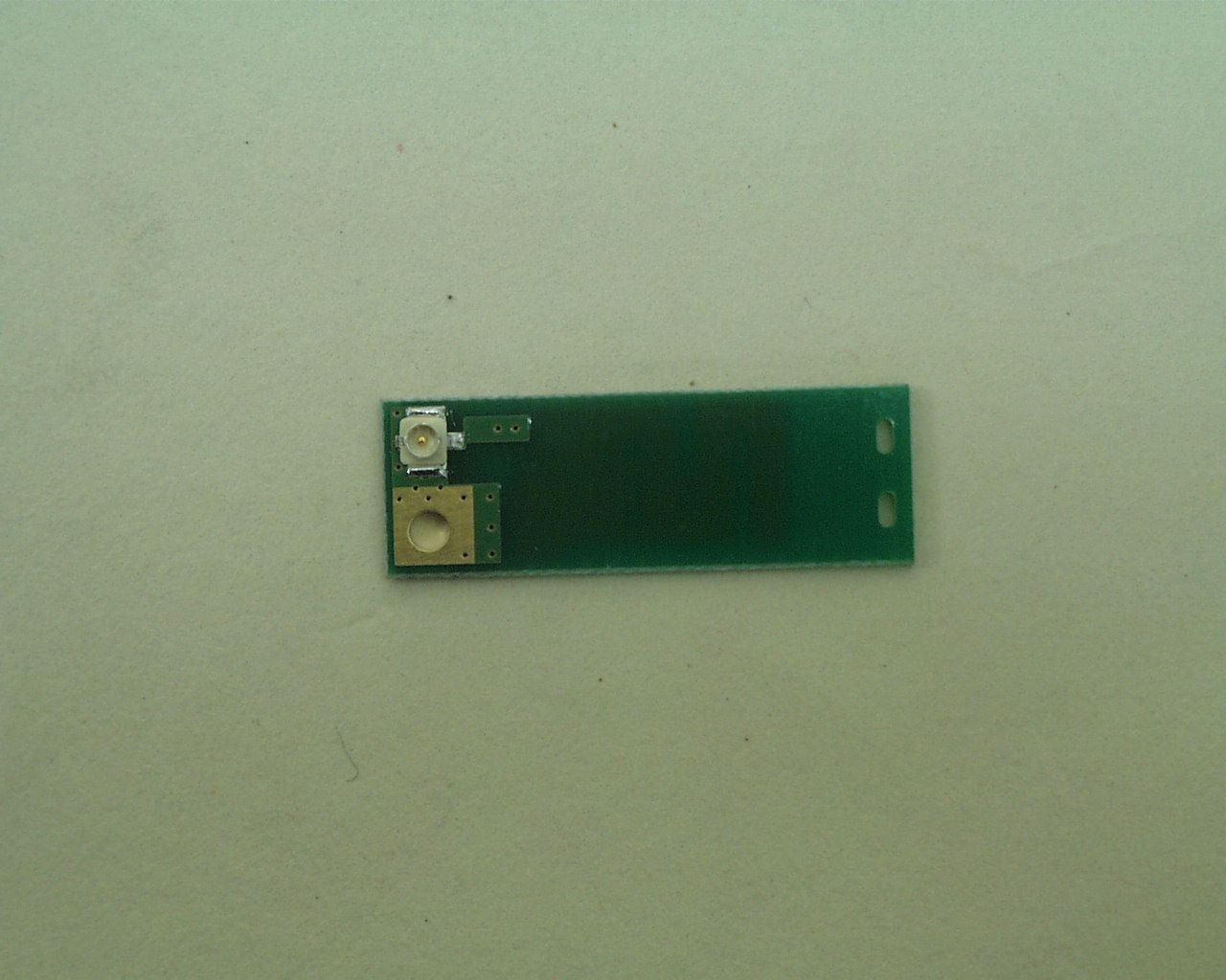
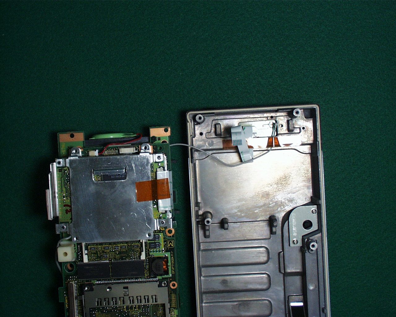
Wireless LAN radio module (WLM-1) for CF-07 , CF-VDW07Description Rev. 0.1 Contents 1. Abstract 2. Technical Specification 3. Antenna Specification 4. Diagram -Theory of Operation -Block Diagram -Photo Revision History RevDateAuthorSummary of Changes 0.12001/07/02Akira ItohInitial Release for FCC Submission 1. Abstract This Panasonic radio module ( WLM-1) provides a wireless connection for Panasonic Mobile Data Wireless Display PC (Display: CF-VDW07 Main Unit: CF-07) in accordance with IEEE standard 802.11DSSS (Direct Sequence Spread Spectrum). It can work at 11, 5.5, 2 or 1 Mbps. The product, one piece of hardware, contains the following blocks; -50pin proprietary connecor; this interface is compatible 16bits PC Card standard (PCMCIA) electrically. -Wireless Medium Access Control (WMAC); this chip is used for handshaking with the 16bits PC Card standard interface (PCMCIA bus) and for handling the IEEE protocol; it also does frequency management and interface to FlashROM for parameters on frequencies and call codes. Here also selection for 11, 5.5, 2, or 1 Mbps is handled. -Baseband processor takes care of all modulation/demodulation for DSSS for all above rates. -A antenna connector provides a connection to external antenna. Please refer to the Theory of Operation for the description of tranmitter and receiver blocks. 2. Technical Specification Frequency Range2412 – 2462 MHz Channel Assignments1ch 1ch1ch 1ch2ch 2ch2ch 2ch3ch 3ch3ch 3ch4ch 4ch4ch 4ch5ch 5ch5ch 5ch6ch 6ch6ch 6ch 2412MHz2417MHz2422MHz 2427MHz2432MHz2437MHz 7ch 7ch7ch 7ch8ch 8ch8ch 8ch9ch 9ch9ch 9ch10ch 10ch10ch 10ch11ch 11ch11ch 11ch 2442MHz2447MHz 2452MHz 2457MHz2462MHz Data rates11 , 5.5 , 2 or 1Mbps Peak Output Power13.0dBm (20mW) @ antenna connector on this module 3. Antenna Specification Internal antenna of CF-VDW07 TypePlanar Inverted F-antenna GainMaximum + 4 dBi @ 2450MHz Average -1.7 dBi @2450MHz Internal antenna of CF-07 TypePlanar Inverted F-antenna GainMaximum +1.5 dBi @2450MHz Average -1.9 dBi @2450MHz 4. Diagram 4.1. Theory of Operation The various parts of the Block diagarm are numbered and an explanation is given of these blocks. Transmitter functions: A) Baseband processor (18) Function: Generate spreaded signal with an Barker sequence of 11, the original raw data rate of 1, 2, 5.5 or 11 Megabits is transformed to a symbol rate of one MegaBaud and multiplied with eleven and modulated with a DBPSK modulation for 1Mbps or a DQPSK modulation for 2Mbps.For 5.5Mbps or 11Mbps, it is modulated with a DQPSK CCK(CCK=Complementary Code Keying) modulation.The unfiltered data comes out of I and Q and goes to the up mixer in IF I/Q Modulator (6). B) The above signals are mixed in (6) in a so called quadrature modulator with the Intermediate Frequency (IF) of 374MHz. C) The up mixer is fed by the VCO (7) of 748MHz, which is divided by 2 to 374MHz. D)The SAW filter (8) filters all unwanted mixing products, such that only the 374MHz band remains. E)This signal goes into the RF upmixer in RF/IF converter (9). It is mixed with the RF VCO (16) with a range 2038 to 2110 MHz. F)The signal is fed through a 2.4- 2.5GHz bandpass filter (10) to remove all unwanted mixer Products, and thus to get a clean signal for further processing. G)The signal is amplified in (11), with approx. 30dB to an output level of approx. 13dBm. H)This signal goes to the TX/RX antenna which is integrated into the host device via the special connector. I) The output power is controlled with a so called power feed back loop (12) in which the output power level is controlled via (13) by the baseband processor. Receiver functions: J)The receive signal enters the TX/RX antenna and goes through the 2.4GHz filter (15) to remove all unwanted spectral components in order to deliver a clean signal for receiver. K)This signal goes to the TX/RX switch (14) which is set to RX mode. L)A Low Noise Amplifier (LNA) in RF/IF converter (9) is used to amplify the weak signal to a level fitted for down mixing.The AGC (17) can amplify the signal. M)The down mixer in RF/IF converter (9) mixes the 2.4GHz with 2.1GHz to the 374MHz IF. N)The signal of 374MHz is filtered by a SAW filter (8) which is the same filter as in transmit mode. O)The signal of 374MHz is amplified again in IF I/Q Demodulator (6) and AGC (17) can increase the signal level to the required level. P)This amplified signal goes to the second mixer in (6) . The down mixer in (6) mixes the 374MHz signal down to the I and Q signals. Q)The Baseband processor (18) removes the spreading as present on the signal with a so called autocorrelation function. The resulting output of the processor is a received data rate of 1, 2, 5.5 or 11 Megabits. VCO, PLL and OSC: R)There are two of the blocks that generate a single tone signal for up/down mixing. One is for the IF LO (PLL is in (6) and VCO is (7).) (374MHz), other is for the RF LO (PLL is in (9) and VCO is (16).) (2038-2110MHz). S)All the PLL’s and processor (2) and (18) have one reference Crystal of 44MHz (4) with an accuracy of 25ppm. Genaral circuits: T)Antenna. This module has not antenna diversity function. So it has only one antenna connector. U)Automatic Gain control. Depending on the signal strength and signal quality the baseband processor (18) can choose to increase or decrease the signal level at the digital input, this is done by reducing or increasing the gain in the receiver via the LNA-RF-AGC (in 9) and IF-AGC (in 6). V)The baseband processor (18) can read via the WMAC (2) the registers for programming all Parameters for transmit / receive functions. W)3.3 volt should be supplied for power via the PCMCIA bus. 4.2. Block Diagram Please refer to other document. << Blockdiagram.doc>> 4.4.Photo Top Vie w Bottom View Top I n te rn al Vi e w
Parts List/Tune Up Info
2001.10 ww – – U.FL -LP -A L q w e r q w e r Ø Ø Ø U.FL 50 90 Ø15 5 2.1 q w q w e U.FL-R-SMT U.FL-LP-040 U.FL-LP-066 U.FL-LP-N-2 E.FL-LP-N
RF Exposure Info
Description in the Operating Instruction Federal Communications Commission Radio Frequency Interference Statement Note: This equipment has been tested and found to comply with the limits for a Class B digital device, pursuant to Part 15 of the FCC Rules. These limits are designed to provide reasonable protection against harmful interference in a residential installa-tion. This equipment generates, uses and can radiate radio frequency energy and, if not installed and used in accordance with the instructions, may cause harmful interfer-ence to radio communications. However, there is no guarantee that interference will not occur in a particular installation. If this equipment does cause harmful interfer-ence to radio or television reception, which can be determined by turning the equip-ment off and on, the user is encouraged to try to correct the interference by one or more of the following measures: Reorient or relocate the receiving antenna. Increase the separation between the equipment and receiver. Connect the equipment into an outlet on a circuit different from that to which the receiver is connected. Consult the Panasonic Service Center or an experienced radio/TV technician for help. Warning To assure continued compliance, use only shielded interface cables when connecting to a computer or peripheral. Also, any changes or modifications not expressly ap-proved by the party responsible for compliance could void the user's authority to oper-ate this equipment. FCC RF Exposure Warning: This computer is provided with PC Card slots that could be used with wireless transmitter(s), which will be specifically recommended, when they become available. Other third-party wireless transmitter(s) have not been RF exposure evaluated for use with this computer and may not comply with FCC RF exposure requirements. This device complies with Part 15 of the FCC Rules. Operation is subject to the following two conditions: (1) This device may not cause harmful interference, and (2) This device must accept any interference received, including interference that may cause undesired operation. Responsible Party:Matsushita Electric Corporation of America One Panasonic Way Secaucus, NJ 07094 Tel No:1-800-LAPTOP-5 (1-800-527-8675) CATION: To comply with FCC RF exposure requirements, For body worn operation, this product has been tested and meets the FCC RF exposure guidelines when used with the Panasonic accessories supplied or designated for this product. Use of other accessories may not ensure compliance with FCC RF exposure guidelines.
RF Exposure Info
Description in the Operating Instruction Federal Communications Commission Radio Frequency Interference Statement Note: This equipment has been tested and found to comply with the limits for a Class B digital device, pursuant to Part 15 of the FCC Rules. These limits are designed to provide reasonable protection against harmful interference in a residential installa-tion. This equipment generates, uses and can radiate radio frequency energy and, if not installed and used in accordance with the instructions, may cause harmful interfer-ence to radio communications. However, there is no guarantee that interference will not occur in a particular installation. If this equipment does cause harmful interfer-ence to radio or television reception, which can be determined by turning the equip-ment off and on, the user is encouraged to try to correct the interference by one or more of the following measures: Reorient or relocate the receiving antenna. Increase the separation between the equipment and receiver. Connect the equipment into an outlet on a circuit different from that to which the receiver is connected. Consult the Panasonic Service Center or an experienced radio/TV technician for help. Warning To assure continued compliance, use only shielded interface cables when connecting to a computer or peripheral. Also, any changes or modifications not expressly ap-proved by the party responsible for compliance could void the user's authority to oper-ate this equipment. FCC RF Exposure Warning: This computer is provided with PC Card slots that could be used with wireless transmitter(s), which will be specifically recommended, when they become available. Other third-party wireless transmitter(s) have not been RF exposure evaluated for use with this computer and may not comply with FCC RF exposure requirements. This device complies with Part 15 of the FCC Rules. Operation is subject to the following two conditions: (1) This device may not cause harmful interference, and (2) This device must accept any interference received, including interference that may cause undesired operation. Responsible Party:Matsushita Electric Corporation of America One Panasonic Way Secaucus, NJ 07094 Tel No:1-800-LAPTOP-5 (1-800-527-8675) FCC Radiation Exposure Statement: This equipment complies with FCC radiation exposure limits set forth for an uncontrolled environment. This equipment should be installed and operated with minimum distance 20cm between the radiator and your body (excluding extremities: hands, wrists, and feet).
RF Exposure Info
in accordance with the requirements of FCC Report and Order: ET Docket 93-62, and OET Bulletin 65 Supplement C for TOUGHBOOK 07 MINI PC MODEL: CF-07 FCC ID: N/A SEP 07, 2001 REPORT NO: 01U0927-1 Prepared for MATSUSHITA ELECTRIC INDUATRIAL CO., LTD. 1006 OAZA KADOMA KADOMA OSAKA JAPAN 571 Prepared by COMPLIANCE CERTIFICATION SERVICES 561F MONTEREY ROAD MORGAN HILL, CA 95037, USA TEL: (408) 463-0885 REPORT NO: 01U0927-1 DATE: SEP 7, 2001 FCC ID: N/A EUT: TOUGHBOOK 07 MINI PC Page 2 of 34 CERTIFICATE OF COMPLIANCE (SAR EVALUATION) Dates of Tests: AUGUST 29 – 31, 2001 Report No: 01U0927-1 Test Sample is a: Pre-Production Unit Tx Frequency: 2411.5 – 2462.3 MHz (CDMA) Max. RF Output Power: 20mW based on Manufacture’s Information FCC Classification: Unlicensed Intentional Radiator RF Exposure environment: General Population/Uncontrolled Application Type: Certification FCC Rule Part(s): § 15.247 This wireless portable device has been shown to be capable of compliance for localized specific absorption rate (SAR) for uncontrolled environment/general population exposure limits specified in ANSI/IEEE Std. C95.1-1992 and had been tested in accordance with the measurement procedures specified in FCC OET 65 Supplement C (released on 6/29/2001 see Test Report). I attest to the accuracy of data. All measurements reported herein were performed by me or were made under my supervision and are correct to the best of my knowledge and belief. I assume full responsibility for the completeness of these measurements and vouch for the qualifications of all persons taking them. Steve Cheng EMC Engineering Manager NVLAP accreditation does not constitute any product endorsement by NVLAP or any agency of the United States Government. CCS certifies that no party to this application has been denied the FCC benefits pursuant to Section 5301 of the Anti-Drug Abuse Act of 1988, 21 U.S.C. 853(a). APPLICANT: MATSUSHITA ELECTRIC INDUSTRIAL CO., LTD. 1006 OAZA KADOMA KADOMA OSAKA JAPAN 571 TRADE NAME: PANASONIC MODEL: CF-07 SERIAL NUMBER: N/A (PRE-PRODUCTION) FCC ID: N/A CATEGORY: MOBILE/PORTABLE DSSS DEVICE REPORT NO: 01U0927-1 DATE: SEP 7, 2001 FCC ID: N/A EUT: TOUGHBOOK 07 MINI PC Page 3 of 34 TABLE OF CONTENT 1. EUT DESCRIPTION.............................................................................................. 4 2. REQUIREMENTS FOR COMPLIANCE TESTING DEFINED BY THE FCC ........ 5 3. DOSIMETRIC ASSESSMENT SETUP ................................................................. 6 3.1. MEASUREMENT SYSTEM DIAGRAM ........................................................................................................7 3.2. SYSTEM COMPONENTS ............................................................................................................................8 3.3. EUT ARRANGEMENT ...............................................................................................................................12 4. EUT TUNE-UP PROCEDURE ............................................................................ 14 5. EVALUATION PROCEDURE ............................................................................. 15 5.1. SIMULATED TISSUE LIQUID PARAMETER CONFIRMATION ................................................................15 5.2. SYSTEM ACCURACY VERIFICATION......................................................................................................15 5.3. SAR EVALUATION PROCEDURE.............................................................................................................17 5.4. EXPOSURE LIMIT .....................................................................................................................................18 6. RESULTS............................................................................................................ 19 7. REFERENCES .................................................................................................... 23 8. APPENDIX .......................................................................................................... 24 8.1. EUT PHOTOS ............................................................................................................................................24 8.2. EQUIPMENTS LIST & CALIBRATION INFO .............................................................................................31 8.3. IEEE SCC-34/SC-2 P1528 RECOMMENDED TISSUE DIELECTRIC PARAMETERS .............................32 8.4. EQUIPMENTS CALIBRATION CERTIFICATE ..........................................................................................33 REPORT NO: 01U0927-1 DATE: SEP 7, 2001 FCC ID: N/A EUT: TOUGHBOOK 07 MINI PC Page 4 of 34 1. EUT DESCRIPTION Test Sample is a: Pre-production Unit EUT Type: Mobile/Portable PC with 2.4GHz Direct Sequence Spread Spectrum Transceiver Trade Name: PANASONIC Model(s): CF-07 FCC IDENTIFIER: N/A S/N: N/A (Pre-Production) Tx Frequency: 2411.5 – 2462.3 MHz (CDMA) Application Type: Certification FCC Classification: Unlicensed Intentional Radiator Modulation(s): CDMA FCC Rule Part(s): § 15.247 Max. RF Output Power: 20mW Based on Manufacture Information Antenna Type: Built-in Antenna Dimensions: N/A Dates of Tests: August 29-31, 2001 Report Project No.: 01U0927-1 1 Specific Absorption Rate (SAR) is a measure of the rate of energy absorption due to exposure to an RF transmitting source (wireless portable device). 2 IEEE/ANSI Std. C95.1-1992 limits are used to determine compliance with FCC ET Docket 93-62. APPLICANT: MATSUSHITA ELECTRIC INDUSTRIAL CO., LTD. 1006 OAZA KADOMA KADOMA OSAKA JAPAN 571 TRADE NAME: PANASONIC MODEL: CF-07 SERIAL NUMBER: N/A (PRE-PRODUCTION) FCC ID: N/A CATEGORY: MOBILE/PORTABLE DSSS DEVICE REPORT NO: 01U0927-1 DATE: SEP 7, 2001 FCC ID: N/A EUT: TOUGHBOOK 07 MINI PC Page 5 of 34 2. REQUIREMENTS FOR COMPLIANCE TESTING DEFINED BY THE FCC The US Federal Communications Commission has released the report and order “Guidelines for Evaluating the Environmental Effects of RF Radiation"…
Text truncated - open the document above for the full version.
RF Exposure Info
October 15, 2001 FCC ID: ACJ9TGWLM-1 Confirmation #: EA102350 Applicant: Matsushita Electric Industrial Co Ltd. Statement This Wireless LAN Module is only used to the Display (CF-VDW07) and the Personal Computer (CF-07). On 11 Sept., we submitted the application documents including SAR test data of the Personal Computer (CF-07) only. But, since there is prospect that the display (CF-VDW07) may be also used within 20 cm with fitting on the body, the SAR test for the display was also performed additionally. Following the above, please also find the revised manual of the display (CF-VDW07) with the manual statement. Sincerely yours,
RF Exposure Info
in accordance with the requirements of FCC Report and Order: ET Docket 93-62, and OET Bulletin 65 Supplement C for DSSS TOUCH PANEL TRANSCEIVER MODEL: CF-VDW07 FCC ID: N/A OCTOBER 11, 2001 REPORT NO: 01U1008-1 Prepared for MATSUSHITA ELECTRIC INDUSTRIAL CO., LTD. 1006 OAZA KADOMA KADOMA OSAKA JAPAN 571 Prepared by COMPLIANCE CERTIFICATION SERVICES 561F MONTEREY ROAD, MORGAN HILL, CA 95037, USA TEL: (408) 463-0885 REPORT NO: 01U1008-1 DATE: October 11.2001 FCC ID: N/A EUT: DSSS Touch Panel Transceiver COMPLIANCE CERTIFICATION SERVICES 2 of 30 DOCUMENT NO: CCSUP4031A 561F MONTEREY ROAD, MORGAN HILL, CA 95037 USA TEL: (408) 463-0885 FAX: (408) 463-0888 This report shall not be reproduced except in full, without the written approval of CCS. This document may be altered or revised by Compliance Certification Services personnel only, and shall be noted in the revision section of the document. CERTIFICATE OF COMPLIANCE (SAR EVALUATION) Dates of Tests: October 10-11, 2001 Report No: 01U1008-1 Test Sample is a: Pre-Production Unit Tx Frequency: 2412 – 2462 MHz (CDMA) Max. RF Output Power: 13mW based on Manufacture’s Information FCC Classification: Unlicensed Intentional Radiator RF Exposure environment: General Population/Uncontrolled Application Type: Certification FCC Rule Part(s): § 15.247 This wireless portable device has been shown to be capable of compliance for localized specific absorption rate (SAR) for uncontrolled environment/general population exposure limits specified in ANSI/IEEE Std. C95.1-1992 and had been tested in accordance with the measurement procedures specified in FCC OET 65 Supplement C (released on 6/29/2001 see Test Report). I attest to the accuracy of data. All measurements reported herein were performed by me or were made under my supervision and are correct to the best of my knowledge and belief. I assume full responsibility for the completeness of these measurements and vouch for the qualifications of all persons taking them. Steve Cheng EMC Engineering Manager NVLAP accreditation does not constitute any product endorsement by NVLAP or any agency of the United States Government. CCS certifies that no party to this application has been denied the FCC benefits pursuant to Section 5301 of the Anti-Drug Abuse Act of 1988, 21 U.S.C. 853(a). APPLICANT: MATSUSHITA ELECTRIC INDUSTRIAL CO., LTD. 1006 OAZA KADOMA KADOMA OSAKA JAPAN 571 TRADE NAME: PANASONIC MODEL: CF-VDW07 SERIAL NUMBER: N/A (PRE-PRODUCTION) FCC ID: N/A CATEGORY: MOBILE/PORTABLE DSSS DEVICE REPORT NO: 01U1008-1 DATE: October 11.2001 FCC ID: N/A EUT: DSSS Touch Panel Transceiver COMPLIANCE CERTIFICATION SERVICES 3 of 30 DOCUMENT NO: CCSUP4031A 561F MONTEREY ROAD, MORGAN HILL, CA 95037 USA TEL: (408) 463-0885 FAX: (408) 463-0888 This report shall not be reproduced except in full, without the written approval of CCS. This document may be altered or revised by Compliance Certification Services personnel only, and shall be noted in the revision section of the document. TABLE OF CONTENT 1. EUT DESCRIPTION.............................................................................................. 4 2. REQUIREMENTS FOR COMPLIANCE TESTING DEFINED BY THE FCC ........ 5 3. DOSIMETRIC ASSESSMENT SETUP ................................................................. 6 3.1. MEASUREMENT SYSTEM DIAGRAM ........................................................................................................7 3.2. SYSTEM COMPONENTS ............................................................................................................................8 3.3. EUT ARRANGEMENT ...............................................................................................................................12 4. EUT TUNE-UP PROCEDURE ............................................................................ 15 5. EVALUATION PROCEDURE ............................................................................. 16 5.1. SIMULATED TISSUE LIQUID PARAMETER CONFIRMATION ................................................................16 5.2. SYSTEM ACCURACY VERIFICATION......................................................................................................16 5.3. SAR EVALUATION PROCEDURE.............................................................................................................18 5.4. EXPOSURE LIMIT .....................................................................................................................................19 6. RESULTS............................................................................................................ 20 7. REFERENCES .................................................................................................... 25 8. APPENDIX .......................................................................................................... 26 8.1. EUT PHOTOS ............................................................................................................................................26 8.2. EQUIPMENTS LIST & CALIBRATION INFO .............................................................................................27 8.3. IEEE SCC-34/SC-2 P1528 RECOMMENDED TISSUE DIELECTRIC PARAMETERS .............................28 8.4. EQUIPMENTS CALIBRATION CERTIFICATE ..........................................................................................29 REPORT NO: 01U1008-1 DATE: October 11.2001 FCC ID: N/A EUT: DSSS Touch Panel Transceiver COMPLIANCE CERTIFICATION SERVICES 4 of 30 DOCUMENT NO: CCSUP4031A 561F MONTEREY ROAD, MORGAN HILL, CA 95037 USA TEL: (408) 463-0885 FAX: (408) 463-0888 This report shall not be reproduced except in full, without the written approval of CCS. This document may be altered or revised by Compliance Certification Services personnel only, and shall be noted in the revision section of the document. 1. EUT DESCRIPTION Test Sample is a: Pre-production Unit EUT Type: Mobile/Portable PC with 2.4GHz Direct Sequence Spread Spectru…
Text truncated - open the document above for the full version.
RF Exposure Info
<For U. S. A.> Federal Communications Commission Radio Frequency Interference Statement Note: This equipment has been tested and found to comply with the limits for a Class B digital device, pursuant to Part 15 of the FCC Rules. These limits are designed to provide reasonable protection against harmful interference in a residential installation. This equipment generates, uses and can radiate radio frequency energy and, if not installed and used in accordance with the instructions, may cause harmful interference to radio communications. However, there is no guarantee that interference will not occur in a particular installation. If this equipment does cause harmful interference to radio or television reception, which can be determined by turning the equipment off and on, the user is encouraged to try to correct the interference by one or more of the following measures: ! Reorient or relocate the receiving antenna. ! Increase the separation between the equipment and receiver. ! Connect the equipment into an outlet on a circuit different from that to which the receiver is connected. ! Consult the Panasonic Service Center or an experienced radio/TV technician for help. Wa rn i ng To assure continued compliance, use only shielded interface cables when connecting to a computer or peripheral. Also, any changes or modifications not expressl y approved by t he part y responsible for compliance could void the user’s authority to operate this equipment. This device complies with Part 15 of the FCC Rules. Operation is subject to the following two conditions: (1) This device may not cause harmful interference, and (2) This device must accept any interference received, including interference that may cause undesired operation. Responsible Party:Matsushita Electric Corporation of America One Panasonic Way Secaucus, NJ 07094 Tel No:1-800-LAPTOP-5 (1-800-527-8675) The use of the transmitter module is limited for the data communication between Personal Computer (CF-07) and Display (CF-VDW07) in order not to be used with any other equipment. CAUTION: To comply with FCC RF exposure requirements, For body worn operation, this product has been tested and meets the FCC RF exposure guidelines when used with the Panasonic accessories supplied or designated for this product. Use of other accessories may not ensure compliance with FCC RF exposure guidelines. <For Canada> Indust r…
Text truncated - open the document above for the full version.
Contact Information
Applicant
Ben Botros(Project Manager)
Technical Contact
A-Pex International Co., Ltd.Naoki Sakamoto
108 Yokowa-cho · Ise-shi, Mie-ken · Japan
Non-Technical Contact
A-Pex International Co., Ltd.Kanako Kawakita
[email protected]+81-596-24-8116
Test Firm
UL Japan, Inc.Kazunori Nishimura
Technical Specifications
| # | Rule Parts | Frequency Range | Power Output | Tolerance |
|---|---|---|---|---|
| 1 | 15C | 2.41 GHz - 2.46 GHz | 28.80 mW | ppm |
Other Applications from Panasonic Corporation of North America
ACJ-EAH-A1000
Aug 19, 2026Digital Wireless Stereo Headphones
Equipment Class
DSS - Part 15 Spread Spectrum TransmitterACJ9TGFZVNF3G1
Jun 16, 2026Contactless Smart Card Reader
Equipment Class
DXX - Part 15 Low Power Communication Device Transmitter
ACJ932AM2301
Jan 29, 2025Car AV Control Unit for CDC
Equipment Class
DTS - Digital Transmission SystemACJ96NKX-TGEA60B
Aug 13, 2024DECT Handset
Equipment Class
PUE - Part 15 Unlicensed PCS portable Tx held to earACJ96NKX-TGE630B
Aug 12, 2024DECT Base Unit
Equipment Class
PUB - Part 15 Unlicensed PCS Base Station