ACJ9TGWW18CRadio Module
Panasonic Corporation of North America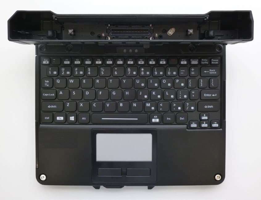
Click to zoom
Application Details
- Equipment Class
- CBE - Citizens Band End User Devices
- Date of Grant
- Jun 30, 2021
- Application Purpose
- Original Equipment
- Date of Application
- May 31, 2021
- Equipment Note
- Radio Module
- Frequency Range
- 3552.50000000 - 3697.50000000
- Country
- United States
Documents & Files
Document Text
Text extracted from the exhibit documents filed with the FCC. Open a document above to read the original.
Users Manual
Contents OPERATING INSTRUCTIONS Read Me First Personal Computer Model No. FZ-G2 series Please read these instructions carefully before using this product, and save this manual for future use. Update the on-screen manuals. Veuillez lire attentivement ces instruction avant d’utiliser ce produit et conservez ce manuel pour une prochaine utilisation. Mettez à jour les manuels qui figurent à l’ecran. Getting Started In these instructions, the names and terms are referred as follows. “Windows 10 Pro” as “Windows” or “Windows 10” This manual explains operation procedures using the touchpad or mouse as typical examples. In addition, you can touch the display screen to operate the computer. When using the touch operation, please replace the terms as described below, and read the instructions. Operation terms to be replaced: - Click → Touch -(Settings):Click (Start) and then click (Settings). è : Page in these Operating Instructions. :Reference to the on-screen manuals. Getting Started Before Turning on the Computer ................. 26 First-time Operation ..................................... 27 Detaching the tablet from the keyboard base .... 33 Attaching the tablet to the keyboard base .... 34 Read Me First / Lecture préliminaire Safety Precautions / Mesures de sécurité ....... 2 Regulatory Information / Informations réglementaires ..... 15 n Terms and illustrations in these instructions Read Me First Appendix Appendix Software License ......................................... 36 2 Read Me First To reduce the risk of injury, loss of life, electric shock, fire, malfunction, and damage to equipment or property, always observe the following safety precautions. Explanation of symbol word panels The following symbol word panels are used to classify and describe the level of hazard, injury, and property damage caused when the denotation is disregarded and improper use is performed. DANGER Denotes a potential hazard that will result in serious injury or death. WARNING Denotes a potential hazard that could result in serious injury or death. CAUTION Denotes a hazard that could result in mi- nor injury. NOTICE Denotes a hazard that could result in property damage. The following symbols are used to classify and describe the type of instructions to be observed. This symbol is used to alert users to a specific operating procedure that must not be performed. This symbol is used to alert users to a specific operating procedure that must be followed in order to operate the unit safety. DANGER Precautions on the Battery Pack Electrolyte leakage, generation of heat, ignition or rupture of the Battery Pack may result. n Do Not Throw the Battery Pack into a Fire or Expose It to Ex- cessive Heat n Do Not Deform, Disassemble, or Modify the Battery Pack n Do Not Short the Positive (+) and Negative (-) Contacts Ö Do not place the battery pack together with articles such as necklaces or hairpins when car- rying or storing. n Do Not Apply Shocks to the Product by Dropping It, Apply- ing Strong Pressure to It, etc. Ö If this product is subjected to a strong impact, remove the battery pack from the computer immediately. n Do Not Charge the Battery Us- ing Methods Other Than Those Specified n Do Not Use the Battery Pack with Any Other Product •The battery pack is rechargeable and was intended for the speci- fied product. n Do Not Use This Product with a Battery Pack Other Than the One Specified Ö Use only the specified battery pack with your product. n Avoid Extreme Heat (Near the Fire, in Direct Sunlight, for Ex- ample) n When the Battery Pack Has De- teriorated or If Abnormal Swell- ing Occur, Replace It with a New One Ö Do not continue to use a dam- aged battery pack. Safety Precautions 3 Read Me First DANGER Precautions on the Battery Pack Electrolyte leakage, generation of heat, ignition or rupture of the Battery Pack may result. n If a Malfunction or Trouble Oc- curs, Immediately Stop Use Ö If the battery pack appears to be damaged or deformed, or if it emits smoke, abnormal odor , excessive heat, or other abnor- mality, remove it from the com- puter immediately. DANGER Precautions on the Built-in Bridge Battery (for disposal) <Only for model with Built-in Bridge Bat- tery> When disposing the battery, generation of heat, ignition or rupture of the Built-in Bridge Battery may result. Handling This Computer n Do Not Disassemble the Com- puter Except When Disposing of It Handling the Built-in Bridge Bat- tery n Do Not Short the Positive (+) and Negative (-) Contacts n Do Not Throw the Battery into a Fire or Expose It to Excessive Heat n Do Not Apply Shocks to the Built-in Bridge Battery by Drop- ping It, Applying Strong Pres- sure to It, etc. n Do Not Charge n Do Not Use n Do Not Deform, Disassemble, or Modify the Built-in Bridge Bat- tery n Avoid Extreme Heat (Near the Fire, in Direct Sunlight, for Ex- ample) WARNING <Only for model with Built-in Bridge Bat- tery> Generation of heat, ignition or rupture of the Built-in Bridge Battery may result. n Do Not Throw This Product Into a Fire or Expose It to Excessive Heat n Do Not Deform, Disassemble, or Modify This Product n Do Not Apply Shocks to the Product by Dropping It, Apply- ing Strong Pressure to It, etc. n Do Not Charge the Battery Us- ing Methods Other Than Those Specified n Avoid Extreme Heat (Near the Fire, In Direct Sunlight, for Ex- ample) n When the Built-in Bridge Battery Has Deteriorated or If Abnormal Swelling Occur, Contact Your Technical Support Office to Re- place the Battery Fire or electric shock may result. n Do Not Do Anything That May Damage the AC Cord, the AC Plug, or the AC Adaptor Do not damage or modify the cord, place it near hot tools, bend, twist, or pull it forcefully, place heavy objects on it, or bundle it tightly. Ö Do not continue to use a dam- aged AC cord, AC plug and AC adaptor. •Contact your technical support office for repair. n Do Not Connect the AC Adaptor to a Power Source Other Than a Standard Household AC Outlet Ö Connect…
Text truncated - open the document above for the full version.
Cover Letter(s)
Panasonic Corporation of North America Two Riverfront Plaza, Newark, NJ 07102-5490 Tel/Fax: 201-348-7760 / [email protected] Ben Botros, Manager – Regulatory & Compliance Panasonic Corporation of North America Agent Authorization Letter March 24, 2021 MSBD-20-F008 UL Japan, Inc. Consumer Technology Division 4383-326 Asama-cho, Ise-shi Mie, 516-0021, Japan Subject: Class II Permissive Change Application for Panasonic Single Modular Model WW18A under FCC ID: ACJ9TGWW18C / Certified Under FCC Parts 22H, 24E, 27 and 90 For Installation within Panasonic Personal Computer Model FZ-G2 To whom it may concern: The undersigned hereby authorize UL Japan, Inc. (UL Japan) to act on our behalf in all manners relating to application for equipment authorization, including signing of all documents relating to these matters. Any and all acts carried out by UL Japan on our behalf shall have the same effect as acts of our own. The undersigned hereby certify that we are not subject to a denial of federal benefits, that includes FCC benefits, pursuant to Section 5301 of the Anti-Drug Abuse Act of 1988, 21 U.S.C. 853(a). In authorizing UL Japan as our agent, we still recognize that we are responsible to: a) comply with the relevant provisions of the certification program; b) make all necessary arrangements for the conduct of the evaluation, including provision for examining documentation and access to all areas, records (including internal audit reports) and personnel for the purposes of evaluation (e.g. testing, inspection, assessment, surveillance, reassessment) and resolution of complaints; c) make claims regarding certification only in respect of the scope for which certification has been granted; d) do not use our product certification in such a manner as to bring the Certification Division into disrepute and not make any statement regarding our product certification which the Certification Division may consider misleading or unauthorized; e) upon suspension or cancellation of certification, discontinue use of all advertising matter that contains any reference thereto and return any certification documents as required by the Certification Division; f) use certification only to indicate the products are certified as being in conformity with specified standards; g) endeavor to ensure that no certificate or report nor any part thereof is used in a misleading manner; Panasonic Corporation of North America Two Riverfront Plaza, Newark, NJ 07102-5490 Tel/Fax: 201-348-7760 / [email protected] Ben Botros, Manager – Regulatory & Compliance Panasonic Corporation of North America h) ensure that any reference to our product certification in communication media such as documents, brochures or advertising, complies with the requirements of the Certification Division; i) keep a record of all complaints made known to the us relating to the product’s compliance with requirements of the relevant standard and to make these records available to the Certification Division when requested; j) take appropriate action with respect to such complaints and any deficiencies found in products or services that affect compliance with the requirements for certification; k) document the actions taken. This authorization is for Single Modular, Model WW18A under FCC ID: ACJ9TGWW18C and is valid for a one year period from the date of this letter. Thank you for your attention in this matter. Sincerely, Ben Botros Manager – Regulatory and Compliance Panasonic Corporation of North America
Cover Letter(s)
Panasonic Corporation of North America Two Riverfront Plaza, Newark, NJ 07102-5490 Tel/Fax: 201-348-7760 / [email protected] Ben Botros, Manager – Regulatory & Compliance Panasonic Corporation of North America Attestation Letter March 24, 2021 MSBD-20-F008 Federal Communications Commission Authorization and Standards Division 7435 Oakland Mills Road Columbia, MD 21046 USA Subject: Class II Permissive Change Application for Panasonic Single Modular Model WW18A under FCC ID: ACJ9TGWW18C / Certified Under FCC Parts 22H, 24E, 27 and 90 For Installation within Panasonic Personal Computer Model FZ-G2 To whom it may concern: We, Panasonic Corporation of North America performed SAR test to mount the module WW18A into the portable host (Panasonic PC Model FZ-G2). The radiated emission testing was not additionally performed due to the following reasons: - The original FCC testing of the module WW18A was performed when the antenna was connected to the module in an open environment. Under this application, the WW18A itself and its antennas installed inside the host PC enclosure. The physical restraints introduced by the host PC enclosure should have resulted in equal or lower level of radiated emission. - Additionally, the integrated host FZ-G2 contains another wireless module (WL20B). However, although both wireless modules (WW18A and WL20B) operate simultaneously, Internal testing confirmed that there is no influence on the emissions levels due to these simultaneous transmissions. Therefore, the host device remains compliant with the regulations. - The original FCC testing of the module WW18A was performed with an antenna of higher gain: 699 MHz - 716 MHz: 6dBi 777 MHz - 787 MHz: 6dBi 788 MHz - 798 MHz: 6dBi 814 MHz - 849 MHz: 6dBi 1710 MHz - 1780 MHz: 6dBi 1850 MHz - 1910 MHz: 6dBi 2305 MHz - 2315 MHz: 1dBi 2496 MHz - 2690 MHz: 9dBi . Thank you for your attention in this matter. Sincerely, Ben Botros Manager – Regulatory and Compliance Panasonic Corporation of North America
Cover Letter(s)
Panasonic Corporation of North America Two Riverfront Plaza, Newark, NJ 07102-5490 Tel/Fax: 201-348-7760 / [email protected] Ben Botros, Manager – Regulatory & Compliance Panasonic Corporation of North America Declaration letter June 8, 2021 MSBD-20-F009 Federal Communications Commission Authorization and Standards Division 7435 Oakland Mills Road Columbia, MD 21046 USA Subject: Class II Permissive C hange Application for Panasonic Single Modular Model WW18A under FCC ID: ACJ9TGWW18C / Certified Under FCC Parts 22H, 24E, 27 and 90 For Installation within Panasonic Personal Computer Model FZ-G2 To whom it may concern: We, Panasonic Corporation of North America declare the following regarding FCC ID: ACJ9TGWW18C 1. MPR is permanently implemented for all channel BWs, modulations, frequency bands and RB sizes. 2. A-MPR was disabled for all SAR test samples for SAR testing purposes only. 3. We confirm the specific MPR targets and tolerances shown in the SAR Report. Should you have any questions or comments concerning the above, please contact the undersigned. Thank you for your attention in this matter. Sincerely, Ben Botros Manager – Regulatory and Compliance Panasonic Corporation of North America
Cover Letter(s)
Panasonic Corporation of North America Two Riverfront Plaza, Newark, NJ 07102-5490 Tel/Fax: 201-348-7760 / [email protected] Ben Botros, Manager – Regulatory & Compliance Panasonic Corporation of North America Request for Permanent & Short-Term Confidentiality June 8, 2021 MSBD-20-F009 UL Japan, Inc. Consumer Technology Division 4383-326 Asama-cho, Ise-shi Mie, 516-0021, Japan Subject: Class II Permissive Change Application for Panasonic Single Modular Model WW18A under FCC ID: ACJ9TGWW18C / Certified Under FCC Parts 22H, 24E, 27 and 90 For Installation within Panasonic Personal Computer Model FZ-G2 To whom it may concern: Pursuant to the provisions of Sections 0.457 and 0.459 of the Commission’s rules (47 CFR §§ 0.457, 0.459), we are requesting the Commission to withhold the following attachments as permanent confidential document from public disclosure. • Theory of Operation - Tune-up and Alignment Procedure • Block Diagrams - Schematics Above mentioned document contains detailed system and equipment description are considered as proprietary information in operation of the equipment. The public disclosure of above documents might be harmful to our company and would give competitor an unfair advantage in the market. In addition, please be advised that Panasonic Corporation of North America hereby requests the following filed sensitive information to be held under short-term confidential, pursuant to the provisions of Sections 0.457 and 0.459 of the Commission’s Rules and the provisions in FCC Public DA 04-1705. We request temporarily confidentiality of 45 days, starting from the original issued Certification grant date. • Operating Instructions (User’s Manual) • External and Internal Photographs • Test Setup Photographs If we require additional 45 day extension period, we will notify UL Japan with a new request letter at least seven days prior to the short-term confidentiality expiration date [Note: up to a maximum of 3 extensions only allowed], or We will immediately notify UL Japan in the event the information regarding the product or the product is made available to the public. UL Japan will then release the documents listed above for public disclosure, pursuant to FCC Public Notice DA 04-1705. . Sincerely, Ben Botros Manager – Regulatory and Compliance Panasonic Corporation of North America
Cover Letter(s)
Panasonic Corporation of North America Two Riverfront Plaza, Newark, NJ 07102-5490 Tel/Fax: 201-348-7760 / [email protected] Ben Botros, Manager – Regulatory & Compliance Panasonic Corporation of North America FCC Modular Approval Declaration June 8, 2021 MSBD-20-F009 Product Information Product Description: Radio Module FRN: 0003762242 Model Name(s): WW18A FCC Product ID: FCC Module ID: ACJ9TGWW18C Modular Checklist/Information For Modular Approval, the module shall meet all the requirements listed below. Please check () if the module complies with the stated requirement. The modular transmitter must have its own shielding. The modular transmitter must have buffered modulation/data inputs. The modular transmitter must have its own power supply regulation. The modular transmitter must comply with the antenna requirements of section 15.203 and 15.204(c). T he modular transmitter must tested in a stand-alone configuration. The modular transmitter must be labeled with its own FCC ID number. The modular transmitter must comply with any specific rule or operating requirements applicable to the transmitter and the manufacturer must provide adequate instruction along with the module to explain any such requirements. The modular transmitter must comply with any applicable RF exposure requirements. If a module(s) does NOT meet one or more of the above listed requirements, the applicant may request Limited Modular Approval (LMA). For LMA, please state details about why the above requirement(s) could not be met; and state how control of the end product, into which the module will be installed, will be maintained by the applicant / manufacturer, such that full compliance of the end product is always ensured: C2PC application for adding CBRS band (Equipment class: CBE) was tested in specific host device, FZ-G2, as non-standalone configuration. Sincerely, Ben Botros Manager – Regulatory and Compliance Panasonic Corporation of North America
External Photos
<FZ-G2> Exterior photos * Over view of Tablet mode <To p> <Rear> <Edge 1> <Edge 2> <Edge 3> <Edge 4> <FZ-G2> Exterior photos * Over view of Laptop mode The Front view The view of Edge2 The view of Edge4 <FZ-G2> Exterior photos *Over view of Keyboard Base The Front view The Backside veiw The view of Edge2 The view of Edge4
External Photos
W WA N FCC ID:ACJ9TGWW18C IC:216H-CFWW18A External photos 1/1 1. WWAN Module photos 1-1. Front view “Shield” <Shield removed> 1-2. Back view Model: WW18A FCC ID: ACJ9TGWW18C IC: 216H-CFWW18A
ID Label/Location Info
FZ-G2 WWAN <FCC ID: ACJ9TGWW18C, IC: 216H-CFWW18A> FCC ID Label location Tablet Mode Rear view Label for FZ-G2 (Under the battery pack)
ID Label/Location Info
W WA N FCC ID :ACJ9TGWW18C IC:216H-CFWW18A Label 1/1 Label 1. Label for WWAN Module 2. Label position Visible outline for Module Model: WW18A FCC ID: ACJ9TGWW18C IC: 216H-CFWW18A
Internal Photos
FZ-G2 Photos 1/2 1) Module location Backside view The bottom cover is opened WLAN/Bluetooth module FCC ID: ACJ9TGWL20B IC: 216H-CFWL20B WWAN module FCC ID: ACJ9TGWW18C IC: 216H-CFWW18A The bottom cover is opened FZ-G2 Photos 2/2 2) Antenna Location Front view W WA N TX/RX Antenna WLAN #1 TX/RX Antenna WLAN #2 and Bluetooth TX/RX Antenna
Internal Photos
W WA N FCC ID:ACJ9TGWW18C IC:216H-CFWW18A External photos 1/1 1. WWAN Module photos 1-1. Front view “Shield” <Shield removed> 1-2. Back view Model: WW18A FCC ID: ACJ9TGWW18C IC: 216H-CFWW18A
RF Exposure Info
Page No. 1 Appendix C SAR System Check Plots 20210204 835MHz System Check Communication System: UID 0, _CW (0); Communication System Band: D835 (835.0 MHz); ; Duty Cycle: 1:1 Medium parameters used: f = 835 MHz; σ = 0.976 S/m; ε r = 54.655; ρ = 1000 kg/m 3 Phantom section: Flat Section DASY5 Configuration Probe: EX3DV4 - SN3917; ConvF(9.78, 9.78, 9.78) @ 835 MHz; Sensor-Surface: 1.4mm (Mechanical Surface Detection), Sensor-Surface: 0mm (Fix Surface) Electronics: DAE4 Sn1369; Phantom: ELI v5.0 TP1207 (30deg probe tilt); Type: QDOVA001BB;Serial: TP:1207 Measurement SW: DASY52, Version 52.10 (3);SEMCAD X Version 14.6.13 (7474) Pin/250mW/Area Scan (61x61x1): Interpolated grid: dx=1.500 mm, dy=1.500 mm Maximum value of SAR (interpolated) = 3.46 W/kg Pin/250mW/Zoom Scan (7x7x7) (7x7x7)/Cube 0: Measurement grid: dx=5mm, dy=5mm, dz=5mm Reference Value = 61.62 V/m; Power Drift = 0.04 dB Peak SAR (extrapolated) = 3.98 W/kg SAR(1 g) = 2.61 W/kg; SAR(10 g) = 1.74 W/kg Smallest distance from peaks to all points 3 dB below = 16.1 mm Ratio of SAR at M2 to SAR at M1 = 66.3% Maximum value of SAR (measured) = 3.49 W/kg Pin/250mW/Z Scan (1x1x31): Measurement grid: dx=20mm, dy=20mm, dz=5mm Maximum value of SAR (measured) = 2.31 W/kg Ambient Temp. : 24.0 degree.C. Liquid Temp.; 23.3 degree.C. Liquid temp. is kept within the 2 degree.C. during the test. Date: 2021/02/04 Page No. 2 Page No. 3 20210222 1750MHz System check. Communication System: UID 0, _CW (0); Communication System Band: D1750 (1750.0 MHz); ; Duty Cycle: 1:1 Medium parameters used: f = 1750 MHz; σ = 1.491 S/m; ε r = 52.53; ρ = 1000 kg/m 3 Phantom section: Flat Section DASY5 Configuration Probe: EX3DV4 - SN3917; ConvF(8.1, 8.1, 8.1) @ 1750 MHz; Sensor-Surface: 1.4mm (Mechanical Surface Detection) Electronics: DAE4 Sn1369; Phantom: ELI v5.0 TP1207 (30deg probe tilt); Type: QDOVA001BB;Serial: TP:1207 Measurement SW: DASY52, Version 52.10 (3);SEMCAD X Version 14.6.13 (7474) Pin=250mW/1750MHz/Area Scan (61x81x1): Interpolated grid: dx=1.500 mm, dy=1.500 mm Maximum value of SAR (interpolated) = 14.5 W/kg Pin=250mW/1750MHz/Zoom Scan (7x7x7)/Cube 0: Measurement grid: dx=5mm, dy=5mm, dz=5mm Reference Value = 101.2 V/m; Power Drift = -0.04 dB Peak SAR (extrapolated) = 16.6 W/kg SAR(1 g) = 9.24 W/kg; SAR(10 g) = 4.92 W/kg Smallest distance from peaks to all points 3 dB below = 10 mm Ratio of SAR at M2 to SAR at M1 = 56.3% Maximum value of SAR (measured) = 14.1 W/kg Pin=250mW/1750MHz/Z Scan (1x1x7): Measurement grid: dx=20mm, dy=20mm, dz=5mm Maximum value of SAR (measured) = 14.1 W/kg Ambient Temp. : 25.0 degree.C. Liquid Temp.; 23.8 degree.C. Liquid temp. is kept within the 2 degree.C. during the test. Date: 2021/02/22 Page No. 4 Page No. 5 20210226 1750MHz System check. Communication System: UID 0, _CW (0); Communication System Band: D1750 (1750.0 MHz); ; Duty Cycle: 1:1 Medium parameters used: f = 1750 MHz; σ = 1.489 S/m; ε r = 52.409; ρ = 1000 kg/m 3 Phantom section: Flat Section DASY5 Configuration Probe: EX3DV4 - SN3917; ConvF(8.1, 8.1, 8.1) @ 1750 MHz; Sensor-Surface: 1.4mm (Mechanical Surface Detection) Electronics: DAE4 Sn1369; Phantom: ELI v5.0 TP1207 (30deg probe tilt); Type: QDOVA001BB;Serial: TP:1207 Measurement SW: DASY52, Version 52.10 (3);SEMCAD X Version 14.6.13 (7474) Pin=250mW/1750MHz/Area Scan (61x81x1): Interpolated grid: dx=1.500 mm, dy=1.500 mm Maximum value of SAR (interpolated) = 14.1 W/kg Pin=250mW/1750MHz/Zoom Scan (7x7x7)/Cube 0: Measurement grid: dx=5mm, dy=5mm, dz=5mm Reference Value = 100.2 V/m; Power Drift = 0.03 dB Peak SAR (extrapolated) = 16.5 W/kg SAR(1 g) = 9.26 W/kg; SAR(10 g) = 4.94 W/kg Smallest distance from peaks to all points 3 dB below = 9.5 mm Ratio of SAR at M2 to SAR at M1 = 56.8% Maximum value of SAR (measured) = 14.1 W/kg Pin=250mW/1750MHz/Z Scan (1x1x7): Measurement grid: dx=20mm, dy=20mm, dz=5mm Maximum value of SAR (measured) = 14.0 W/kg Ambient Temp. : 23.0 degree.C. Liquid Temp.; 22.1 degree.C. Liquid temp. is kept within the 2 degree.C. during the test. Date: 2021/02/26 Page No. 6 Page No. 7 20210304 2600MHz System Check Communication System: UID 0, _CW (0); Communication System Band: D2600 (2600.0 MHz); ; Duty Cycle: 1:1 Medium parameters used: f = 2600 MHz; σ = 2.147 S/m; ε r = 50.117; ρ = 1000 kg/m 3 Phantom section: Flat Section DASY5 Configuration Probe: EX3DV4 - SN3917; ConvF(7.37, 7.37, 7.37) @ 2600 MHz; Sensor-Surface: 1.4mm (Mechanical Surface Detection) Electronics: DAE4 Sn1369; Phantom: ELI v5.0 TP1207 (30deg probe tilt); Type: QDOVA001BB;Serial: TP:1207 Measurement SW: DASY52, Version 52.10 (3);SEMCAD X Version 14.6.13 (7474) Pin=250mW/2600MHz/Area Scan (71x101x1): Interpolated grid: dx=1.200 mm, dy=1.200 mm Maximum value of SAR (interpolated) = 24.4 W/kg Pin=250mW/2600MHz/Zoom Scan (7x7x7)/Cube 0: Measurement grid: dx=5mm, dy=5mm, dz=5mm Reference Value = 108.1 V/m; Power Drift = -0.00 dB Peak SAR (extrapolated) = 30.0 W/kg SAR(1 g) = 13.8 W/kg; SAR(10 g) = 6.09 W/kg Smallest distance from peaks to all points 3 dB below = 8.9 mm Ratio of SAR at M2 to SAR at M1 = 46.6% Maximum value of SAR (measured) = 23.5 W/kg Pin=250mW/2600MHz/Z Scan (1x1x18): Measurement grid: dx=20mm, dy=20mm, dz=5mm Penetration depth = 7.175 (6.516, 7.238) [mm] Maximum value of SAR (interpolated) = 29.7 W/kg Ambient Temp. : 22.5 degree.C. Liquid Temp.; 22.0 degree.C. Liquid temp. is kept within the 2 degree.C. during the test. Date: 2021/03/04 Page No. 8 Page No. 9 20210308 2600MHz System Check Communication System: UID 0, _CW (0); Communication System Band: D2600 (2600.0 MHz); ; Duty Cycle: 1:1 Medium parameters used: f = 2600 MHz; σ = 2.158 S/m; ε r = 50.507; ρ = 1000 kg/m 3 Phantom section: Flat Section DASY5 Configuration Probe: EX3DV4 - SN3917; ConvF(7.37, 7.37, 7.37) @ 2600 MHz; Sensor-Surface: 1.4mm (Mechanical Surface Detection) Electronics: DAE4 Sn1369; Phantom: ELI v5.0 TP1207 (30deg probe tilt); Type: QDOVA001BB;Serial: TP:1207 Measurement SW: DASY52, Version 52.10 (3);SEMCAD X Version 14.6.13 (7474) Pin=25…
Text truncated - open the document above for the full version.
RF Exposure Info
Plot No. 1 Appendix D Highest SAR Test Plots WCDMA B2 Full Power/Rear tilt(Edge4 side) 9mm 1880MHz RMC12.2k Communication System: UID 0, _WCDMA (0); Communication System Band: Band II; ; Duty Cycle: 1:1 Medium parameters used: f = 1880 MHz; σ = 1.49 S/m; ε r = 53.102; ρ = 1000 kg/m 3 Phantom section: Flat Section DASY5 Configuration Probe: EX3DV4 - SN3917; ConvF(7.93, 7.93, 7.93) @ 1880 MHz; Sensor-Surface: 1.4mm (Mechanical Surface Detection) Electronics: DAE4 Sn1369; Phantom: ELI v5.0 TP1207 (30deg probe tilt); Type: QDOVA001BB;Serial: TP:1207 Measurement SW: DASY52, Version 52.10 (3);SEMCAD X Version 14.6.13 (7474) WCDMA B2 Full Power/Rear tilt(Edge4 side) 9mm 1880MHz RMC12.2k/Area Scan (111x51x1): Interpolated grid: dx=1.500 mm, dy=1.500 mm Maximum value of SAR (interpolated) = 1.27 W/kg WCDMA B2 Full Power/Rear tilt(Edge4 side) 9mm 1880MHz RMC12.2k/Zoom Scan (8x7x7)/Cube 0: Measurement grid: dx=5mm, dy=5mm, dz=5mm Reference Value = 30.43 V/m; Power Drift = -0.21 dB Peak SAR (extrapolated) = 1.46 W/kg SAR(1 g) = 0.872 W/kg; SAR(10 g) = 0.511 W/kg Smallest distance from peaks to all points 3 dB below = 14 mm Ratio of SAR at M2 to SAR at M1 = 60.1% Maximum value of SAR (measured) = 1.24 W/kg Ambient Temp. : 23.5 degree.C. Liquid Temp.; 22.7 degree.C. Liquid temp. is kept within the 2 degree.C. during the test. Date: 2021/03/17 Plot No. 2 WCDMA B2 Red Power/Edge4 0mm 1907.6MHz RMC12.2k Communication System: UID 0, _WCDMA (0); Communication System Band: Band II; ; Duty Cycle: 1:1 Medium parameters used (interpolated): f = 1907.6 MHz; σ = 1.522 S/m; ε r = 53.033; ρ = 1000 kg/m 3 Phantom section: Flat Section DASY5 Configuration Probe: EX3DV4 - SN3917; ConvF(7.93, 7.93, 7.93) @ 1907.6 MHz; Sensor-Surface: 1.4mm (Mechanical Surface Detection) Electronics: DAE4 Sn1369; Phantom: ELI v5.0 TP1207 (30deg probe tilt); Type: QDOVA001BB;Serial: TP:1207 Measurement SW: DASY52, Version 52.10 (3);SEMCAD X Version 14.6.13 (7474) WCDMA B2 Red Power/Edge4 0mm 1907.6MHz RMC12.2k/Area Scan (51x111x1): Interpolated grid: dx=1.500 mm, dy=1.500 mm Maximum value of SAR (interpolated) = 1.54 W/kg WCDMA B2 Red Power/Edge4 0mm 1907.6MHz RMC12.2k/Zoom Scan (7x7x7)/Cube 0: Measurement grid: dx=5mm, dy=5mm, dz=5mm Reference Value = 34.68 V/m; Power Drift = -0.01 dB Peak SAR (extrapolated) = 2.07 W/kg SAR(1 g) = 1.09 W/kg; SAR(10 g) = 0.534 W/kg Smallest distance from peaks to all points 3 dB below = 8 mm Ratio of SAR at M2 to SAR at M1 = 54.8% Maximum value of SAR (measured) = 1.70 W/kg Ambient Temp. : 23.5 degree.C. Liquid Temp.; 22.7 degree.C. Liquid temp. is kept within the 2 degree.C. during the test. Date: 2021/03/17 Plot No. 3 WCDMA B4 Full Power/Rear tilt(Edge4 side) 9mm 1732.6MHz Communication System: UID 0, #WCDMA (0); Communication System Band: Band IV; ; Duty Cycle: 1:1 Medium parameters used (interpolated): f = 1732.6 MHz; σ = 1.493 S/m; ε r = 52.562; ρ = 1000 kg/m 3 Phantom section: Flat Section DASY5 Configuration Probe: EX3DV4 - SN3825; ConvF(7.98, 7.98, 7.98) @ 1732.6 MHz; Sensor-Surface: 1.4mm (Mechanical Surface Detection) Electronics: DAE4 Sn509; Phantom: ELI v4.0 (20deg probe tilt); Type: QDOVA001BB;Serial: TP:1045 Measurement SW: DASY52, Version 52.10 (3);SEMCAD X Version 14.6.13 (7474) WCDMA B4 Full Power/Rear tilt(Edge4 side) 9mm 1732.6MHz/Area Scan (91x61x1): Interpolated grid: dx=1.500 mm, dy=1.500 mm Maximum value of SAR (interpolated) = 1.04 W/kg WCDMA B4 Full Power/Rear tilt(Edge4 side) 9mm 1732.6MHz/Zoom Scan (7x7x7)/Cube 0: Measurement grid: dx=5mm, dy=5mm, dz=5mm Reference Value = 26.89 V/m; Power Drift = -0.02 dB Peak SAR (extrapolated) = 1.17 W/kg SAR(1 g) = 0.729 W/kg; SAR(10 g) = 0.443 W/kg Smallest distance from peaks to all points 3 dB below = 15.2 mm Ratio of SAR at M2 to SAR at M1 = 62.5% Maximum value of SAR (measured) = 1.01 W/kg Ambient Temp. : 22.5 degree.C. Liquid Temp.; 22.0 degree.C. Liquid temp. is kept within the 2 degree.C. during the test. Date: 2021/03/19 Plot No. 4 WCDMA B4 Red Power/Edge4 0mm 1732.6MHz Communication System: UID 0, #WCDMA (0); Communication System Band: Band IV; ; Duty Cycle: 1:1 Medium parameters used (interpolated): f = 1732.6 MHz; σ = 1.493 S/m; ε r = 52.562; ρ = 1000 kg/m 3 Phantom section: Flat Section DASY5 Configuration Probe: EX3DV4 - SN3825; ConvF(7.98, 7.98, 7.98) @ 1732.6 MHz; Sensor-Surface: 1.4mm (Mechanical Surface Detection) Electronics: DAE4 Sn509; Phantom: ELI v4.0 (20deg probe tilt); Type: QDOVA001BB;Serial: TP:1045 Measurement SW: DASY52, Version 52.10 (3);SEMCAD X Version 14.6.13 (7474) WCDMA B4 Red Power/Edge4 0mm 1732.6MHz/Area Scan (51x111x1): Interpolated grid: dx=1.500 mm, dy=1.500 mm Maximum value of SAR (interpolated) = 1.07 W/kg WCDMA B4 Red Power/Edge4 0mm 1732.6MHz/Zoom Scan (7x7x7)/Cube 0: Measurement grid: dx=5mm, dy=5mm, dz=5mm Reference Value = 28.18 V/m; Power Drift = 0.02 dB Peak SAR (extrapolated) = 1.37 W/kg SAR(1 g) = 0.729 W/kg; SAR(10 g) = 0.364 W/kg Smallest distance from peaks to all points 3 dB below = 8 mm Ratio of SAR at M2 to SAR at M1 = 55.8% Maximum value of SAR (measured) = 1.14 W/kg Ambient Temp. : 22.5 degree.C. Liquid Temp.; 22.0 degree.C. Liquid temp. is kept within the 2 degree.C. during the test. Date: 2021/03/19 Plot No. 5 WCDMA B5 Full Power/Rear tilt(Edge4 side) 9mm 836.6MHz RMC12.2k Communication System: UID 0, _WCDMA (0); Communication System Band: Band V; ; Duty Cycle: 1:1 Medium parameters used (interpolated): f = 836.6 MHz; σ = 1.009 S/m; ε r = 55.542; ρ = 1000 kg/m 3 Phantom section: Flat Section DASY5 Configuration Probe: EX3DV4 - SN3917; ConvF(9.78, 9.78, 9.78…
Text truncated - open the document above for the full version.
Contact Information
Applicant
Ben Botros(Manager - Regulatory & Compliance)
Technical Contact
Test Firm
UL Japan, Inc. Head office EMC Lab.Tetsuya Hashimoto
Technical Specifications
| # | Rule Parts | Frequency Range | Power Output | Emission | Tolerance |
|---|---|---|---|---|---|
| 8 | 96 | 3.55 GHz - 3.70 GHz | 113.00 mW | 4M52W7D | 2.5 ppm |
Other Applications from Panasonic Corporation of North America
ACJ-EAH-A1000
Aug 19, 2026Digital Wireless Stereo Headphones
Equipment Class
DSS - Part 15 Spread Spectrum TransmitterACJ9TGFZVNF3G1
Jun 16, 2026Contactless Smart Card Reader
Equipment Class
DXX - Part 15 Low Power Communication Device Transmitter
ACJ932AM2301
Jan 29, 2025Car AV Control Unit for CDC
Equipment Class
DTS - Digital Transmission SystemACJ96NKX-TGEA60B
Aug 13, 2024DECT Handset
Equipment Class
PUE - Part 15 Unlicensed PCS portable Tx held to earACJ96NKX-TGE630B
Aug 12, 2024DECT Base Unit
Equipment Class
PUB - Part 15 Unlicensed PCS Base Station