ACJODSDLFD201Internal SCSI DVD RAM Drive
Panasonic Corporation of North America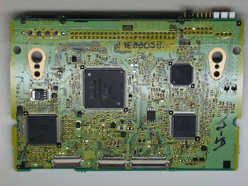
Click to zoom
Application Details
- Equipment Class
- JBP - Part 15 Class B Computing Device Peripheral
- Date of Grant
- Feb 08, 2000
- Application Purpose
- Original Equipment
- Date of Application
- Jan 31, 2000
- Equipment Note
- Internal SCSI DVD RAM Drive
- Country
- United States
Documents & Files
Document Text
Text extracted from the exhibit documents filed with the FCC. Open a document above to read the original.
Users Manual
- 19 - Attachment A User Manual
Attestation Statements
- 1 - MEASUREMENT/TECHNICAL REPORT COMPANY NAME MODEL LF-D201 FCC ID:ACJODSDLFD201 January 14, 2000 This report concerns(check one):Original grant X Class II change Equipment type: Optical Disk Drive(DVD-RAM Drive) (ex: computer, printer, etc.) Request issue of grant(check one): X Immediately upon completion of view. Defer grant per 47 CFR 0.457(d)(1)(ii)until date . Company Name agrees to notify the Commission by date of the intended date of announcement of the product so that the grant can be issued on that date. Measurement procedure used:(check one) ANSI C63.4-1992 X Other If other, describe Applicant for Certification Prepared by: Your name Masataka Maeda Your company name MATSUSHITA ELECTRIC INDUSTRIAL CO.,LTD. STORAGE DEVICE BUSINESS DEPARTMENT Your address 1-15,MATSUO-CHO,KADOMA,OSAKA,571-8504 JAPAN Your phone number 06-6906-2333 Your FAX number 06-6906-2343 Your mail address 1-15,MATSUO-CHO,KADOMA,OSAKA,571-8504 JAPAN - 2 - Table of Contents 1 GENERAL INFORMATION4 1.1 Product Description4 1.2 Related Submittal(s)/Grant(s)4 1.3 Tested System Details4 1.4 Tested Methodology4 1.5 Test Facility4 1.6 Referenced Rules Sections4 2 PRODUCT LABELING5 Figure 2.1 FCC ID Label5 Figure 2.2 Location of Label on EUT6 3 SYSTEM TEST CONFIGURATION7 3.1 Justification7 3.2 Video Mode Justification7 3.3 EUT Exercise Software7 3.4 Special Accessories7 3.5 Equipment Modifications7 3.6 Configuration of Tested System7 Figure 3.1 Configuration of Tested System7 4 BLOCK DIAGRAM(S) OF EQUIPMENT8 4.1 Block Diagram Operation8 4.2 Theory of Operation10 Figure 4.1 Block Diagram of Model10 5 CONDUCTED AND RADIATED MEASUREMENT PHOTOS11 6 CONDUCTED EMISSION DATA11 6.1 Test Procedure11 6.2 Measured Data11 6.3 Referenced Rules Sections11 6.4 Test Instrumentation Used, Conducted Measurement11 7 RADIATED EMISSION DATA11 7.1 Test Procedure11 7.2 Test Data11 7.3 Referenced Rules Sections11 7.4 Test Instrumentation Used, Radiated Measurement11 7.5 Field Strength Calculation11 8 PHOTOS OF TESTED EUT12 Figure 1 Front View13 Figure 2 Top View13 Figure 3 Right Side View14 Figure 4Left Side View14 Figure 5Rear View15 Figure 6Bottom View15 Figure 7Processor PC Board, Up Side16 Figure 8Processor PC Board, Down Side16 Figure 9Top Cover Removed(1)17 Figure10Top Cover Removed(2)17 Figure11Top Cover Removed(3)18 Attachment A. User Manual19 Attachment B. Engineering Test Report20 - 3 - STANDARD FORMAT MESUREMENT / TECHNICAL REPORT PERSONAL COMPUTER AND PERIPHERAL - 4 - 1 GENERAL INFORMATION 1.1 Product Description Please make reference to the Sheet 4 of Engineering Test Report A-068-99-A written by Kansai Electronic Industry Development Center. 1.2 Related Submittal/Grant N/A 1.3 Tested System Details The FCC IDs for all equipment, plus descriptions of all cables used in the tested system (including inserted cards, which have grants)are: Please make reference to the Sheet 8,9 of Engineering Test Report A-068-99-A written by Kansai Electronic Industry Development Center. 1.4 Test Methodology Please make reference to the Sheet 10,16 of Engineering Test Report A-068-99-A written by Kansai Electronic Industry Development Center. 1.5 Test Facility Please make reference to the Sheet 5 of Engineering Test Report A-068-99-A written by Kansai Electronic Industry Development Center. 1.6 Referenced Rules Sections N/A - 5 - 2 PRODUCT LABELING Figure 2.1 FCC ID Label - 6 - Figure 2.2 Location of Label on EUT - 7 - 3 SYSTEM TEST CONFIGURATION 3.1 Justification This disk drive is an optical disk drive which can play audio CD disk, can read CD-ROM disk at 24x(Max.) speed of the CD specification and can read and write the phase change rewritable optical disk called "DVD-RAM disk" using same mechanism. This drive is used as the internal storage device in the personal computer. Therefore, the verification tests of this device were carried out by using CD-ROM disk, the DVD-RAM disk after installing this device into the personal computer. For the verification test using CD-ROM disk, this disk drive was connected to the built-in sound board of the personal computer, tested with playing audio sound and data transfer from CD-ROM disk through SCSI interface at 24x(Max.) speed. For the verification test using DVD-RAM disk, this disk drive was tested with data transfer operation from hard disk drive in the personal computer to DVD-RAM disk drive and from DVD-RAM disk drive to the hard disk drive through SCSI interface. 3.2 Video Mode Justification N/A 3.3 EUT Exercise Software Please make reference to the Sheet 6 of Engineering Test Report A-068-99-A written by Kansai Electronic Industry Development Center. 3.4 Special Accessories N/A 3.5 Equipment Modifications N/A 3.6 Configuration of Tested System Please make reference to the Sheet 7 of Engineering Test Report A-068-99-A written by Kansai Electronic Industry Development Center. Figure 3.1 Configuration of Tested System Please make reference to the Sheet 7 of Engineering Test Report A-068-99-A written by Kansai Electronic Industry Development Center. - 8 - 4 BLOCK DIAGRAM OF EQUIPMENT 4.1 Block Diagram Description This optical disk drive can handle bare disks like CD and CD-ROM disk, DVD-RAM (2.6GB and 4.7GB) disk, which is 12cm phase change rewritable disk with disk cartridge, using same disk tray. In the case of CD and CD-ROM disk, the rotation speed is set to the standard rotation speed of CD specification or 24x(Max.) speed of the specification depending on the medium and the host computer control. The information signal from the CD or CD-ROM disk is retrieved by the laser diode. The laser spot is focused on the disk using objective lens and controlled by the digital serve LSI so as to follow the information track on the disk. The read out signals from the CD or CD-ROM disks are decoded and converted to the digital data using Read Channel Decoder LSI, and after the error correction procedure, the data is transferred to the host computer. In the case of DVD-RAM(2.6GB) disk, the Zoned Constant Liner Velo…
Text truncated - open the document above for the full version.
Block Diagram
- 8 - 4 BLOCK DIAGRAM OF EQUIPMENT 4.1 Block Diagram Description This optical disk drive can handle bare disks like CD and CD-ROM disk, DVD-RAM (2.6GB and 4.7GB) disk, which is 12cm phase change rewritable disk with disk cartridge, using same disk tray. In the case of CD and CD-ROM disk, the rotation speed is set to the standard rotation speed of CD specification or 24x(Max.) speed of the specification depending on the medium and the host computer control. The information signal from the CD or CD-ROM disk is retrieved by the laser diode. The laser spot is focused on the disk using objective lens and controlled by the digital serve LSI so as to follow the information track on the disk. The read out signals from the CD or CD-ROM disks are decoded and converted to the digital data using Read Channel Decoder LSI, and after the error correction procedure, the data is transferred to the host computer. In the case of DVD-RAM(2.6GB) disk, the Zoned Constant Liner Velocity (ZCLV) format is used with 24 divided zones on the disk and the rotation speed is set to 1014~2254rpm. The data is recorded at each zone on the DVD-RAM disk with the same recording density using different clock from the synthesizer circuit in the drive and the total recording capacity of the DVD-RAM disk becomes 2.6GB using this recording procedure. The laser spot focused on the DVD-RAM disk is also controlled by the digital servo LSI for focusing and tracking control. For the data recording, the information data transferred from the host computer is encoded to the (8,16), added the parity data for the error correction procedure and converted to the digital signal for recording to the DVD-RAM disk. The converted digital signal is transferred to the Laser Power Controller LSI through the Digital Servo Controller LSI. The laser power for the data recording is modulated between the erase power and the peak power following the information data and the direct overwrite is achieved by using this laser modulation scheme. For the data reading, the read out signal retrieved from the DVD-RAM disk is maintained and converted to the digital signal using the Read Channel LSI, decoded from the (8,16) to the digital data using the Optical Disk Controller LSI and transferred to the host computer. In the case of DVD-RAM(4.7GB) disk, the Zoned Constant Liner Velocity (ZCLV) format is used with 35 divided zones on the disk and the rotation speed is set to 1375~3246rpm. The data is recorded at each zone on the DVD-RAM disk with the same recording density using different clock from the synthesizer circuit in the drive and the total recording capacity of the DVD-RAM disk becomes 4.7GB using this recording procedure. The laser spot focused on the DVD-RAM disk is also controlled by the digital servo LSI for focusing and tracking control. For the data recording, the information data transferred from the host computer is encoded to the (8,16), added the parity data for the error correction procedure and converted to the digital signal for recording to the DVD-RAM disk. The converted digital signal is transferred to the Laser Power Controller LSI through the Digital Servo Controller LSI. The laser power for the data recording is modulated between the erase power and the peak power following the information data and the direct overwrite is achieved by using this laser modulation scheme. For the data reading, the read out signal retrieved from the DVD-RAM disk is maintained - 9 - and converted to the digital signal using the Read Channel LSI, decoded from the (8,16) to the digital data using the Optical Disk Controller LSI and transferred to the host computer. - 10 - 4.2 Theory of Operation Please make reference to the chapter 4.1 Figure 4.1 Block Diagram of Model
External Photos
- 13 - Figure1 Front View Figure2 Top View - 14 - Figure3 Right Side View Figure4 Left Side View - 15 - Figure5 Rear View Figure6 Bottom View - 16 - Figure7 Processor PC Board, Up Side Figure8 Processor PC Board, Down Side - 17 - Figure9 Top Cover Removed(1) Figure10 Top Cover Removed(2) - 18 - Figure11 Top Cover Removed(3)
ID Label/Location Info
- 5 - 2 PRODUCT LABELING Figure 2.1 FCC ID Label - 6 - Figure 2.2 Location of Label on EUT
Test Report
A-068-99-APage 1 of 23 KEC Ikoma Testing Laboratory 12128 Takayama-cho Ikoma-city Nara 630-0101 Japan Designated by Ministry of international Trade and industry KANSAI ELECTRONIC INDUSTRY DEVELOPMENT CENTER HEAD OFFICE IKOMA TESTING LABORATORY 6-8-7 NISHITENMA 12128 TAKAYAMA-CHO KITA-KU OSAKA 530-0047 JAPAN IKOMA-CITY NARA 630-0101 JAPAN Corporate Juridical Person TEST REPORT Report No.A-068-99-ADate: 20 December 1999 This test report is to certify that the tested device properly complies with the requirements of: FCC Rules and Regulations Part 15 Subpart B Unintentional Radiators. All the tests necessary to show compliance to the requirements were performed and these results met the specifications of requirement. The results of this report should not be construed to imply compliance of equipment other than that, which was tested. Unless the laboratory permission, this report should not be copied in part. 1. Applicant Company Name:Matsushita Electric Industrial Co., Ltd. ADD Group, Storage Device Business Department Mailing Address:1-15 Matsuo-cho, Kadoma, Osaka, 571-8504 Japan 2. Identification of Tested Device Type of Device:Digital Device Kind of Equipment Authorization:: DoC : Certification: Verification FCC ID:ACJODSDLFD201 Device Name:DVD-RAM Drive Trade Name: Panasonic Model Number: LF-D201 Serial Number:ES3-L1: Prototype : Pre-production : Production Date of Manufacture:November, 1999 3. Test Items and Procedure : AC Power Line Conducted Emission Measurement : Radiated Emission Measurement Above all tests were performed under: ANSI C63.4 – 1992 : without deviation, : with deviation(details are found inside of this report) 4. Date of Test Receipt of Test Sample:8 December 1999 Test Completed on: 9 December 1999 Fumitoshi Nagaoka Associate Director/ Ikoma Testing Laboratory A-068-99-APage 2 of 23 KEC Ikoma Testing Laboratory 12128 Takayama-cho Ikoma-city Nara 630-0101 Japan Table of Contents 0.NVLAP ACCREDITATION AND MEASUREMENT UNCERTAINTY.......................3 0.1.NVLAP Accreditation.........................................................................................3 0.2.Measurement Uncertainty.................................................................................3 1.CERTIFICATION OF THE COMPLIANCE..............................................................3 2.GENERAL INFORMATION.....................................................................................4 2.1.Product Description...........................................................................................4 2.2.Description for Equipment Authorization...........................................................5 2.3.Test Facility.......................................................................................................5 3.TESTED SYSTEM....................................................................................................6 3.1.Test Mode..........................................................................................................6 3.2.Operation of EUT System..................................................................................6 3.3.Characterization and condition of EUT System..................................................6 3.4.Block Diagram of EUT System...........................................................................7 3.5.List of EUT System............................................................................................8 3.6.List of Cables.....................................................................................................9 4.AC POWER LINE CONDUCTED EMISSION MEASUREMENT...........................10 4.1.Test Procedure.................................................................................................10 4.2.Test Results.....................................................................................................11 4.3.Photographs of EUT System Configuration......................................................13 5.RADIATED EMISSION MEASUREMENT.............................................................16 5.1.Test Procedure.................................................................................................16 5.2.Test Results.....................................................................................................17 5.3.Photographs of EUT System Configuration......................................................21 6.LIST OF TEST EQUIPMENTS...............................................................................23 A-068-99-APage 3 of 23 KEC Ikoma Testing Laboratory 12128 Takayama-cho Ikoma-city Nara 630-0101 Japan 0. NVLAP ACCREDITATION AND MEASUREMENT UNCERTAINTY 0.1. NVLAP Accreditation KEC is accredited by the National Voluntary Accreditation Program for the specific scope of accreditation under Lab Code: 200207-0. When a test report concerns with the NVLAP Accreditation test, the first page of the test report is sighed by NVLAP Approved Signatory together with the expression. The report must not be used by the client to claim product endorsement by NVLAP or any agency of the U.S. Government. 0.2. Measurement Uncertainty The result of a measurement is only an approximation or estimate of the value of a specific quantity. And thus the measurand is complete only when a statement of uncertainty is given. KEC quotes Measurement Uncertainty (U) of +/- 4.9 dB for Radiated Emissions and of +/- 2.2 dB for Conducted Emissions. 1. CERTIFICATION OF THE COMPLIANCE This test report is to certify that the tested device properly complies with the requirements of FCC Rules and Regulations Part 15 Subpart B Unintentional Radiators. KEC evaluation criteria for compliance: The Product complies, if the measured results are below the specification limit by a margin more than or equal 1/2U (2.5 dB) for Radiated Emissions and U (2.2 dB) for Conducted Emissions. A-068-99-APage 4 of 23 KEC Ikoma Testing Laboratory 12128 Takayama-cho Ikoma-city Nara 630-0101 Japan 2. GENERAL INFORMATI…
Text truncated - open the document above for the full version.
Contact Information
Applicant
Ben Botros(Project Manager)
Technical Contact
Matsushita Electric Corp of AmericaRichard Mullen
[email protected](201) 348-7758
One Panasonic Way, 4B-8 · Secaucus, New Jersey · United States
Test Firm
Kansai Electronic Industry Dev. Ct.Eizo Hariya
Technical Specifications
| # | Rule Parts | Frequency Range | Power Output |
|---|---|---|---|
| 1 | 15B | - | - |
Other Applications from Panasonic Corporation of North America
ACJ-EAH-A1000
Aug 19, 2026Digital Wireless Stereo Headphones
Equipment Class
DSS - Part 15 Spread Spectrum TransmitterACJ9TGFZVNF3G1
Jun 16, 2026Contactless Smart Card Reader
Equipment Class
DXX - Part 15 Low Power Communication Device Transmitter
ACJ932AM2301
Jan 29, 2025Car AV Control Unit for CDC
Equipment Class
DTS - Digital Transmission SystemACJ96NKX-TGEA60B
Aug 13, 2024DECT Handset
Equipment Class
PUE - Part 15 Unlicensed PCS portable Tx held to earACJ96NKX-TGE630B
Aug 12, 2024DECT Base Unit
Equipment Class
PUB - Part 15 Unlicensed PCS Base Station