ACJODSDLFD211Internal DVD-RAM Drive With Headphone Jack
Panasonic Corporation of North America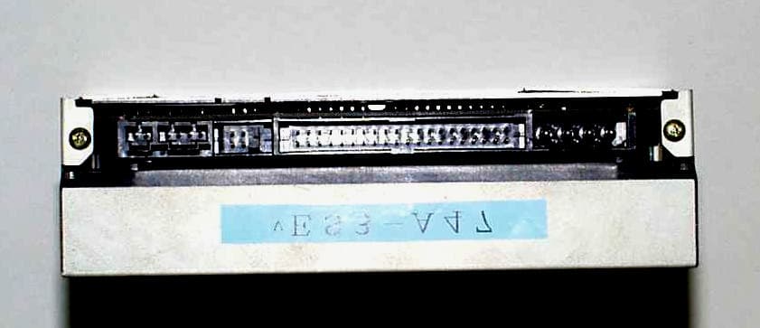
Click to zoom
Application Details
- Equipment Class
- JBP - Part 15 Class B Computing Device Peripheral
- Date of Grant
- Nov 21, 1999
- Application Purpose
- Original Equipment
- Date of Application
- Nov 02, 1999
- Equipment Note
- Internal DVD-RAM Drive With Headphone Jack
- Country
- United States
Documents & Files
Document Text
Text extracted from the exhibit documents filed with the FCC. Open a document above to read the original.
External Photos
- 13 - Figure1 Front View Figure2 Top View - 14 - Figure3 Right Side View Figure4 Left Side View - 15 - Figure5 Rear View Figure6 Bottom View
ID Label/Location Info
- 5 - 2 PRODUCT LABELING Figure 2.1 FCC ID Label - 6 - Figure 2.2 Location of Label on EUT
Internal Photos
- 16 - Figure7 Processor PC Board, Up Side Figure8 Processor PC Board, Down Side - 17 - Figure9 Top Cover Removed(1) Figure10 Top Cover Removed(2) - 18 - Figure11 Top Cover Removed(3) Attachment A
Test Report
A-061-99-APage 1 of 25 KEC Ikoma Testing Laboratory 12128 Takayama-cho Ikoma-city Nara 630-0101 Japan Designated by Ministry of international Trade and industry KANSAI ELECTRONIC INDUSTRY DEVELOPMENT CENTER HEAD OFFICE IKOMA TESTING LABORATORY 6-8-7 NISHITENMA 12128 TAKAYAMA-CHO KITA-KU OSAKA 530-0047 JAPAN IKOMA-CITY NARA 630-0101 JAPAN Corporate Juridical Person TEST REPORT Report No.A-061-99-ADate: 25 October 1999 This test report is to certify that the tested device properly complies with the requirements of: FCC Rules and Regulations Part 15 Subpart B Unintentional Radiators. All the tests necessary to show compliance to the requirements were performed and these results met the specifications of requirement. The results of this report should not be construed to imply compliance of equipment other than that, which was tested. Unless the laboratory permission, this report should not be copied in part. 1. Applicant Company Name:Matsushita Electric Industrial Co., Ltd. ADD Group, Storage Device Business Department Mailing Address:1-15 Matsuo-cho, Kadoma, Osaka, 571-8504 Japan 2. Identification of Tested Device Type of Device:Digital Device Kind of Equipment Authorization:: DoC : Certification: Verification FCC ID:ACJODSDLFD211 Device Name:DVD-RAM Drive Trade Name: Non Brand Model Number: LF-D211N Serial Number:ES3-A4: Prototype : Pre-production : Production Date of Manufacture:October 1999 3. Test Items and Procedure : AC Power Line Conducted Emission Measurement : Radiated Emission Measurement Above all tests were performed under: ANSI C63.4 – 1992 : without deviation, : with deviation(details are found inside of this report) 4. Date of Test Receipt of Test Sample:18 October 1999 Test Completed on: 18 October 1999 Fumitoshi Nagaoka Associate Director/ Ikoma Testing Laboratory A-061-99-APage 2 of 25 KEC Ikoma Testing Laboratory 12128 Takayama-cho Ikoma-city Nara 630-0101 Japan Table of Contents 0.NVLAP ACCREDITATION AND MEASUREMENT UNCERTAINTY......3 0.1.NVLAP Accreditation.........................................................................................3 0.2.Measurement Uncertainty.................................................................................3 1.CERTIFICATION OF THE COMPLIANCE...................................3 2.GENERAL INFORMATION....................................................4 2.1.Product Description...........................................................................................4 2.2.Description for Equipment Authorization...........................................................5 2.3.Test Facility.......................................................................................................5 3.TESTED SYSTEM...............................................................6 3.1.Test Mode..........................................................................................................6 3.2.Operation of EUT System..................................................................................6 3.3.Characterization and condition of EUT System..................................................6 3.4.Block Diagram of EUT System...........................................................................7 3.5.List of EUT System............................................................................................9 3.6.List of Cables...................................................................................................10 4.AC POWER LINE CONDUCTED EMISSION MEASUREMENT..........12 4.1.Test Procedure.................................................................................................12 4.2.Test Results.....................................................................................................13 4.3.Photographs of EUT System Configuration......................................................15 5.RADIATED EMISSION MEASUREMENT...................................18 5.1.Test Procedure.................................................................................................18 5.2.Test Results.....................................................................................................19 5.3.Photographs of EUT System Configuration......................................................23 6.LIST OF TEST EQUIPMENTS................................................25 A-061-99-APage 3 of 25 KEC Ikoma Testing Laboratory 12128 Takayama-cho Ikoma-city Nara 630-0101 Japan 0. NVLAP ACCREDITATION AND MEASUREMENT UNCERTAINTY 0.1. NVLAP Accreditation KEC is accredited by the National Voluntary Accreditation Program for the specific scope of accreditation under Lab Code: 200207-0. When a test report concerns with the NVLAP Accreditation test, the first page of the test report is sighed by NVLAP Approved Signatory together with the expression. The report must not be used by the client to claim product endorsement by NVLAP or any agency of the U.S. Government. 0.2. Measurement Uncertainty The result of a measurement is only an approximation or estimate of the value of a specific quantity. And thus the measurand is complete only when a statement of uncertainty is given. KEC quotes Measurement Uncertainty (U) of +/- 4.9 dB for Radiated Emissions and of +/- 2.2 dB for Conducted Emissions. 1. CERTIFICATION OF THE COMPLIANCE This test report is to certify that the tested device properly complies with the requirements of FCC Rules and Regulations Part 15 Subpart B Unintentional Radiators. KEC evaluation criteria for compliance: The Product complies, if the measured results are below the specification limit by a margin more than or equal 1/2U (2.5 dB) for Radiated Emissions and U (2.2 dB) for Conducted Emissions. A-061-99-APage 4 of 25 KEC Ikoma Testing Laboratory 12128 Takayama-cho Ikoma-city Nara 630-0101 Japan 2. GENERAL INFORMATION 2.1. Product Description The Model No. LF-D211 (referred to as the EUT in this report) is a DVD-RAM Drive. The EUT is built in the personal computer by using the ATAPI connector. (1) Techn…
Text truncated - open the document above for the full version.
Test Report
A-061-99-APage 1 of 25 KEC Ikoma Testing Laboratory 12128 Takayama-cho Ikoma-city Nara 630-0101 Japan Designated by Ministry of international Trade and industry KANSAI ELECTRONIC INDUSTRY DEVELOPMENT CENTER HEAD OFFICE IKOMA TESTING LABORATORY 6-8-7 NISHITENMA 12128 TAKAYAMA-CHO KITA-KU OSAKA 530-0047 JAPAN IKOMA-CITY NARA 630-0101 JAPAN Corporate Juridical Person TEST REPORT Report No.A-061-99-ADate: 25 October 1999 This test report is to certify that the tested device properly complies with the requirements of: FCC Rules and Regulations Part 15 Subpart B Unintentional Radiators. All the tests necessary to show compliance to the requirements were performed and these results met the specifications of requirement. The results of this report should not be construed to imply compliance of equipment other than that, which was tested. Unless the laboratory permission, this report should not be copied in part. 1. Applicant Company Name:Matsushita Electric Industrial Co., Ltd. ADD Group, Storage Device Business Department Mailing Address:1-15 Matsuo-cho, Kadoma, Osaka, 571-8504 Japan 2. Identification of Tested Device Type of Device:Digital Device Kind of Equipment Authorization:: DoC : Certification: Verification FCC ID:ACJODSDLFD211 Device Name:DVD-RAM Drive Trade Name: Non Brand Model Number: LF-D211N Serial Number:ES3-A4: Prototype : Pre-production : Production Date of Manufacture:October 1999 3. Test Items and Procedure : AC Power Line Conducted Emission Measurement : Radiated Emission Measurement Above all tests were performed under: ANSI C63.4 – 1992 : without deviation, : with deviation(details are found inside of this report) 4. Date of Test Receipt of Test Sample:18 October 1999 Test Completed on: 18 October 1999 Fumitoshi Nagaoka Associate Director/ Ikoma Testing Laboratory A-061-99-APage 2 of 25 KEC Ikoma Testing Laboratory 12128 Takayama-cho Ikoma-city Nara 630-0101 Japan Table of Contents 0.NVLAP ACCREDITATION AND MEASUREMENT UNCERTAINTY......3 0.1.NVLAP Accreditation.........................................................................................3 0.2.Measurement Uncertainty.................................................................................3 1.CERTIFICATION OF THE COMPLIANCE...................................3 2.GENERAL INFORMATION....................................................4 2.1.Product Description...........................................................................................4 2.2.Description for Equipment Authorization...........................................................5 2.3.Test Facility.......................................................................................................5 3.TESTED SYSTEM...............................................................6 3.1.Test Mode..........................................................................................................6 3.2.Operation of EUT System..................................................................................6 3.3.Characterization and condition of EUT System..................................................6 3.4.Block Diagram of EUT System...........................................................................7 3.5.List of EUT System............................................................................................9 3.6.List of Cables...................................................................................................10 4.AC POWER LINE CONDUCTED EMISSION MEASUREMENT..........12 4.1.Test Procedure.................................................................................................12 4.2.Test Results.....................................................................................................13 4.3.Photographs of EUT System Configuration......................................................15 5.RADIATED EMISSION MEASUREMENT...................................18 5.1.Test Procedure.................................................................................................18 5.2.Test Results.....................................................................................................19 5.3.Photographs of EUT System Configuration......................................................23 6.LIST OF TEST EQUIPMENTS................................................25 A-061-99-APage 3 of 25 KEC Ikoma Testing Laboratory 12128 Takayama-cho Ikoma-city Nara 630-0101 Japan 0. NVLAP ACCREDITATION AND MEASUREMENT UNCERTAINTY 0.1. NVLAP Accreditation KEC is accredited by the National Voluntary Accreditation Program for the specific scope of accreditation under Lab Code: 200207-0. When a test report concerns with the NVLAP Accreditation test, the first page of the test report is sighed by NVLAP Approved Signatory together with the expression. The report must not be used by the client to claim product endorsement by NVLAP or any agency of the U.S. Government. 0.2. Measurement Uncertainty The result of a measurement is only an approximation or estimate of the value of a specific quantity. And thus the measurand is complete only when a statement of uncertainty is given. KEC quotes Measurement Uncertainty (U) of +/- 4.9 dB for Radiated Emissions and of +/- 2.2 dB for Conducted Emissions. 1. CERTIFICATION OF THE COMPLIANCE This test report is to certify that the tested device properly complies with the requirements of FCC Rules and Regulations Part 15 Subpart B Unintentional Radiators. KEC evaluation criteria for compliance: The Product complies, if the measured results are below the specification limit by a margin more than or equal 1/2U (2.5 dB) for Radiated Emissions and U (2.2 dB) for Conducted Emissions. A-061-99-APage 4 of 25 KEC Ikoma Testing Laboratory 12128 Takayama-cho Ikoma-city Nara 630-0101 Japan 2. GENERAL INFORMATION 2.1. Product Description The Model No. LF-D211 (referred to as the EUT in this report) is a DVD-RAM Drive. The EUT is built in the personal computer by using the ATAPI connector. (1) Techn…
Text truncated - open the document above for the full version.
Test Report
A-061-99-APage 1 of 25 KEC Ikoma Testing Laboratory 12128 Takayama-cho Ikoma-city Nara 630-0101 Japan Designated by Ministry of international Trade and industry KANSAI ELECTRONIC INDUSTRY DEVELOPMENT CENTER HEAD OFFICE IKOMA TESTING LABORATORY 6-8-7 NISHITENMA 12128 TAKAYAMA-CHO KITA-KU OSAKA 530-0047 JAPAN IKOMA-CITY NARA 630-0101 JAPAN Corporate Juridical Person TEST REPORT Report No.A-061-99-ADate: 25 October 1999 This test report is to certify that the tested device properly complies with the requirements of: FCC Rules and Regulations Part 15 Subpart B Unintentional Radiators. All the tests necessary to show compliance to the requirements were performed and these results met the specifications of requirement. The results of this report should not be construed to imply compliance of equipment other than that, which was tested. Unless the laboratory permission, this report should not be copied in part. 1. Applicant Company Name:Matsushita Electric Industrial Co., Ltd. ADD Group, Storage Device Business Department Mailing Address:1-15 Matsuo-cho, Kadoma, Osaka, 571-8504 Japan 2. Identification of Tested Device Type of Device:Digital Device Kind of Equipment Authorization:: DoC : Certification: Verification FCC ID:ACJODSDLFD211 Device Name:DVD-RAM Drive Trade Name: Non Brand Model Number: LF-D211N Serial Number:ES3-A4: Prototype : Pre-production : Production Date of Manufacture:October 1999 3. Test Items and Procedure : AC Power Line Conducted Emission Measurement : Radiated Emission Measurement Above all tests were performed under: ANSI C63.4 – 1992 : without deviation, : with deviation(details are found inside of this report) 4. Date of Test Receipt of Test Sample:18 October 1999 Test Completed on: 18 October 1999 Fumitoshi Nagaoka Associate Director/ Ikoma Testing Laboratory A-061-99-APage 2 of 25 KEC Ikoma Testing Laboratory 12128 Takayama-cho Ikoma-city Nara 630-0101 Japan Table of Contents 0.NVLAP ACCREDITATION AND MEASUREMENT UNCERTAINTY......3 0.1.NVLAP Accreditation.........................................................................................3 0.2.Measurement Uncertainty.................................................................................3 1.CERTIFICATION OF THE COMPLIANCE...................................3 2.GENERAL INFORMATION....................................................4 2.1.Product Description...........................................................................................4 2.2.Description for Equipment Authorization...........................................................5 2.3.Test Facility.......................................................................................................5 3.TESTED SYSTEM...............................................................6 3.1.Test Mode..........................................................................................................6 3.2.Operation of EUT System..................................................................................6 3.3.Characterization and condition of EUT System..................................................6 3.4.Block Diagram of EUT System...........................................................................7 3.5.List of EUT System............................................................................................9 3.6.List of Cables...................................................................................................10 4.AC POWER LINE CONDUCTED EMISSION MEASUREMENT..........12 4.1.Test Procedure.................................................................................................12 4.2.Test Results.....................................................................................................13 4.3.Photographs of EUT System Configuration......................................................15 5.RADIATED EMISSION MEASUREMENT...................................18 5.1.Test Procedure.................................................................................................18 5.2.Test Results.....................................................................................................19 5.3.Photographs of EUT System Configuration......................................................23 6.LIST OF TEST EQUIPMENTS................................................25 A-061-99-APage 3 of 25 KEC Ikoma Testing Laboratory 12128 Takayama-cho Ikoma-city Nara 630-0101 Japan 0. NVLAP ACCREDITATION AND MEASUREMENT UNCERTAINTY 0.1. NVLAP Accreditation KEC is accredited by the National Voluntary Accreditation Program for the specific scope of accreditation under Lab Code: 200207-0. When a test report concerns with the NVLAP Accreditation test, the first page of the test report is sighed by NVLAP Approved Signatory together with the expression. The report must not be used by the client to claim product endorsement by NVLAP or any agency of the U.S. Government. 0.2. Measurement Uncertainty The result of a measurement is only an approximation or estimate of the value of a specific quantity. And thus the measurand is complete only when a statement of uncertainty is given. KEC quotes Measurement Uncertainty (U) of +/- 4.9 dB for Radiated Emissions and of +/- 2.2 dB for Conducted Emissions. 1. CERTIFICATION OF THE COMPLIANCE This test report is to certify that the tested device properly complies with the requirements of FCC Rules and Regulations Part 15 Subpart B Unintentional Radiators. KEC evaluation criteria for compliance: The Product complies, if the measured results are below the specification limit by a margin more than or equal 1/2U (2.5 dB) for Radiated Emissions and U (2.2 dB) for Conducted Emissions. A-061-99-APage 4 of 25 KEC Ikoma Testing Laboratory 12128 Takayama-cho Ikoma-city Nara 630-0101 Japan 2. GENERAL INFORMATION 2.1. Product Description The Model No. LF-D211 (referred to as the EUT in this report) is a DVD-RAM Drive. The EUT is built in the personal computer by using the ATAPI connector. (1) Techn…
Text truncated - open the document above for the full version.
Test Report
A-061-99-APage 18 of 25 KEC Ikoma Testing Laboratory 12128 Takayama-cho Ikoma-city Nara 630-0101 Japan 5. RADIATED EMISSION MEASUREMENT 5.1. Test Procedure (1) Configure the EUT System in accordance with ANSI C63.4-1992 section 8. : without deviation, : with deviation(details are found below) See also the block diagram and the photographs of EUT System configuration in this report. (2) If the EUT system is connected to a public power network, all power cords for the EUT System are connected the receptacle on the turntable. (3) Warm up the EUT System. (4) Activate the EUT System and run the prepared software for the test, if necessary. (5)To find out the emissions of the EUT System, preliminary radiated measurement are performed at a closer distance than that specified for final radiated measurement using the spectrum analyzer (*1) and the broad band antenna. In the frequency above 1 GHz, it is performed using the spectrum analyzer (*2) and the horn antenna. (6) To find out an EUT System condition, which produces the maximum emission, the configuration of EUT System, the position of the cables, and the operation mode, are changed under normal usage of the EUT. (7) The spectrums are scanned from 30 MHz to the upper frequency of measurement range, and collect the six highest emissions minimum on the spectrum analyzer relative to the limits in the whole range. (8)In final compliance test, the six highest emissions minimum, recorded above, are measured at the specified distance using the broad band antenna or the tuned dipole antenna and the test receiver (*3). In the frequency above 1 GHz, the measurements are performed by the horn antenna and the test receiver (*4). the spectrum analyzer(*2). [Note] (*1)Spectrum Analyzer Set Up Conditions Frequency range: 30 - 1000 MHz Resolution bandwidth: 100 kHz Detector function: Peak mode (*2)Spectrum Analyzer Set Up Conditions Frequency range: 1 GHz - Upper frequency of measurement range Resolution bandwidth: 1 MHz Video bandwidth: 1 MHz Attenuator: 10 dB Detector function: Peak mode (*3)Test Receiver Set Up Conditions Detector function: Quasi-Peak IF bandwidth: 120 kHz (*4)Test Receiver Set Up Conditions Detector function: Average IF bandwidth: 1 MHz A-061-99-APage 19 of 25 KEC Ikoma Testing Laboratory 12128 Takayama-cho Ikoma-city Nara 630-0101 Japan 5.2. Test Results (1) DVD-RAM operation mode Measurement Distance : 3m : 10m Measured Frequency Antenna Factor Meter ReadingMaximum Field Strength LimitsMargin for Limits HorizontalVertical ( MHz )( dB )( dBuV )( dBuV )( dBuV/m )( dBuV/m )( dB ) 35.3516.6 6.013.430.040.010.0 36.4716.1 5.414.430.540.0 9.5 106.8912.9 8.113.226.143.517.4 159.7617.112.410.129.543.514.0 196.6118.716.512.635.243.5 8.3 239.9719.714.4 7.634.146.011.9 * 314.4821.621.011.642.646.0 3.4 368.6618.417.514.035.946.010.1 425.0119.715.3 9.735.046.011.0 576.9023.310.8 9.034.146.011.9 720.1825.5 7.4 4.532.946.013.1 943.6628.010.1 9.038.146.0 7.9 1032.35 -11.842.844.332.554.021.5 1265.54 -12.940.040.427.554.026.5 1465.56 -13.334.139.025.754.028.3 [Note] (1) Antenna Factor includes the cable loss. (2) *mark in Measured Frequency: Measured with the tuned dipole antenna. nomark in Measured Frequency: Measured with the broadband antenna. (3) Above 1000 MHz, the antenna factor is includes both of a cable loss and pre-amplifier gain. [Calculation method] Maximum Field Strength (dBuV/m) = Meter Reading (at maximum level of Horizontal or Vertical) (dBuV) + Antenna Factor (dB) [Environment] Temperature: 17Humidity: 75 [Tested Date/ Tester] 18 October 1999Signature Ikuya Minematsu A-061-99-APage 20 of 25 KEC Ikoma Testing Laboratory 12128 Takayama-cho Ikoma-city Nara 630-0101 Japan Test Results in Graph (1) DVD-RAM operation mode [Note] O: Maximum Field Strength : Limit Line Radiated Emission Measurement Frequency ( MHz ) Field Strength ( dBuV/m ) A-061-99-APage 21 of 25 KEC Ikoma Testing Laboratory 12128 Takayama-cho Ikoma-city Nara 630-0101 Japan (2)CD-ROM operation mode Measurement Distance : 3m : 10m Measured Frequency Antenna Factor Meter ReadingMaximum Field Strength LimitsMargin for Limits HorizontalVertical ( MHz )( dB )( dBuV )( dBuV )( dBuV/m )( dBuV/m )( dB ) 35.3516.6 4.613.630.240.0 9.8 36.4716.1 2.013.129.240.010.8 159.7217.113.5 9.530.643.512.9 196.6118.716.412.635.143.5 8.4 199.4218.810.0 7.728.843.514.7 239.9719.713.6 7.333.346.012.7 368.6318.415.011.733.446.012.6 380.9318.716.410.035.146.010.9 542.9622.5 6.214.036.546.0 9.5 576.8823.3 7.813.837.146.0 8.9 742.0525.9 4.1 7.633.546.012.5 911.9928.1 3.4 4.832.946.013.1 1032.40 -11.839.442.530.754.023.3 1250.88 -12.737.337.524.854.029.2 [Note] (1) Antenna Factor includes the cable loss. (2) *mark in Measured Frequency: Measured with the tuned dipole antenna. nomark in Measured Frequency: Measured with the broadband antenna. (3) Above 1000 MHz, the antenna factor is includes both of a cable loss and pre-amplifier gain. [Calculation method] Maximum Field Strength (dBuV/m) = Meter Reading (at maximum level of Horizontal or Vertical) (dBuV) + Antenna Factor (dB) [Environment] Temperature: 17Humidity: 75 [Tested Date/ Tester] 18 October 1999Signature Ikuya Minematsu A-061-99-APage 22 of 25 KEC Ikoma Testing Laboratory 12128 Takayama-cho Ikoma-city Nara 630-0101 Japan Test Results in Graph (2) CD-ROM operation mode [Note] O: Maximum Field Strength : Limit Line Radiated Emission Measurement Frequency ( MHz ) Field Strength ( dBuV/m )
Test Setup Photos
A-061-99-APage 15 of 25 KEC Ikoma Testing Laboratory 12128 Takayama-cho Ikoma-city Nara 630-0101 Japan 4.3. Photographs of EUT System Configuration Maximum operation mode FRONT VIEW A-061-99-APage 16 of 25 KEC Ikoma Testing Laboratory 12128 Takayama-cho Ikoma-city Nara 630-0101 Japan - Continued - Maximum operation mode LEFT SIDE VIEW A-061-99-APage 17 of 25 KEC Ikoma Testing Laboratory 12128 Takayama-cho Ikoma-city Nara 630-0101 Japan - Continued - Maximum operation mode RIGHT SIDE VIEW
Test Setup Photos
A-061-99-APage 23 of 25 KEC Ikoma Testing Laboratory 12128 Takayama-cho Ikoma-city Nara 630-0101 Japan 5.3. Photographs of EUT System Configuration Maximum operation mode FRONT VIEW A-061-99-APage 24 of 25 KEC Ikoma Testing Laboratory 12128 Takayama-cho Ikoma-city Nara 630-0101 Japan - Continued - Maximum operation mode REAR VIEW A-061-99-APage 25 of 25 KEC Ikoma Testing Laboratory 12128 Takayama-cho Ikoma-city Nara 630-0101 Japan 6. LIST OF TEST EQUIPMENTS EquipmentManufacturerModel No.SpecificationsKEC Control No. Test Item (*) Last Cal. Next Cal. ESHS10Frequency Range 9 kHz – 30 MHz FS-48-211999/92000/6 ESVS10Frequency Range 20 MHz – 1 GHz FS-8221999/22000/2 Test Receiver Rohde & Schwarz ESVDFrequency Range 20 MHz – 2.05 GHz FS-7931999/42000/4 Spectrum Analyzer AdvantestR3261CFrequency Range 9 kHz – 2.6 GHz SA-412,31999/82000/8 Spectrum Analyzer Hewlett Packard 8568BFrequency Range 100 Hz – 1.5 GHz FS-46-311999/62000/6 Pre-AmprifierHewlett Packard 8449BFrequency Range 1GHz26.5GHz AM-5231999/42000/4 Biconical Antenna SchwarzbeckBBA9106Frequency Range 30 MHz – 300 MHz AN-94 21999/22000/2 Log- Periodic Antenna SchwarzbeckUHALP9108AFrequency Range 300 MHz – 1 GHz AN-21721999/22000/2 KBA-511ASFrequency Range 25 MHz – 500 MHz AN-13521999/32000/3Tuned Dipole Antenna Kyoritsu KBA-611SFrequency Range 500 MHz – 1 GHz AN-137N/A1999/32000/3 Horn AntennaRaven91888-1Frequency Range 1GHz-2GHz AN-16731997/111999/11 LISN for EUT KyoritsuKNW-407Frequency Range 150 kHz – 30 MHz Capacity AC 250V, 15A FL-10711999/42000/4 LISN for Peri- pherals KyoritsuKNW-242Frequency Range 10 kHz – 30 MHz Capacity AC 250V, 15A FL-11011999/42000/4 [Note] Test Item (*):1:Conducted Emission Measurement 2:Radiated Emission Measurement30 MHz – 1 GHz 3:Radiated Emission Measurement1 GHz < N/A:Not Applicable The overall program of calibration and verification of equipment is designed and operated so as to ensure that measurements made by KEC are traceable to national standards of measurement or equivalent abroad.
Contact Information
Applicant
Ben Botros(Project Manager)
Technical Contact
Matsushita Electric Corp. of AmericaRichard Mullen
[email protected](201) 348-7758
One Panasonic Way, Panazip 4B-8 · Secaucus, New Jersey · United States
Test Firm
Kansai Electronic Industry Dev. Ct.Seiichi Izumi
Technical Specifications
| # | Rule Parts | Frequency Range | Power Output |
|---|---|---|---|
| 1 | 15B | - | - |
Other Applications from Panasonic Corporation of North America
ACJ-EAH-A1000
Aug 19, 2026Digital Wireless Stereo Headphones
Equipment Class
DSS - Part 15 Spread Spectrum TransmitterACJ9TGFZVNF3G1
Jun 16, 2026Contactless Smart Card Reader
Equipment Class
DXX - Part 15 Low Power Communication Device Transmitter
ACJ932AM2301
Jan 29, 2025Car AV Control Unit for CDC
Equipment Class
DTS - Digital Transmission SystemACJ96NKX-TGEA60B
Aug 13, 2024DECT Handset
Equipment Class
PUE - Part 15 Unlicensed PCS portable Tx held to earACJ96NKX-TGE630B
Aug 12, 2024DECT Base Unit
Equipment Class
PUB - Part 15 Unlicensed PCS Base Station