ACJODSDLFD311Internal DVD-RAM Drive with Headphone Jack
Panasonic Corporation of North America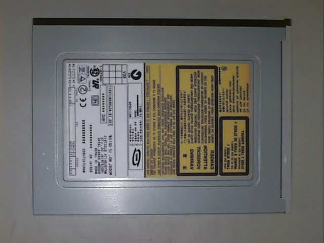
Click to zoom
Application Details
- Equipment Class
- JBP - Part 15 Class B Computing Device Peripheral
- Date of Grant
- May 30, 2001
- Application Purpose
- Original Equipment
- Date of Application
- May 29, 2001
- Equipment Note
- Internal DVD-RAM Drive with Headphone Jack
- Country
- United States
Documents & Files
Document Text
Text extracted from the exhibit documents filed with the FCC. Open a document above to read the original.
Users Manual
User Manual
Block Diagram
Block Diagram Description Driver FEP CPU LPC Motor FROM Laser H-AMP LDD Optical Head Servo DSP DRC Driver ODC ATAPI DRAM (8Mbit) Interface Disc R- FEP
Cover Letter(s)
Matsushita Electric Corporation of America Product Safety & Compliance Division1 Panasonic Way, 4B-8Zameel Shahat Secaucus, NJ 07094Project Engineer PanasonicQuasarTechnicsFax: (201) 392-4564Tel: (201) 392-4161 e-mail:[email protected] May 24, 2001 DAND-01-F201 PCTEST 6660-B Dobbin Road Columbia, MD 21045 Subject: Original Application for TCB Certification of Class B Computing Device Peripheral FCC ID: ACJODSDLFD311 / Internal DVD-RAM Drive, Model LF-D311 Series Gentlemen: Enclosed, find Matsushita Electric Industrial Co., Ltd.'s application for equipment authorization, dated April 27, 2001. This device is in compliance with Part, Subpart B of the FCC Rules. The subject device is an Internal DVD-RAM Drive with ATAPI interface and is provided with a headphone jack. This device can play audio CD disk; can read CD-ROM disk at 24x-speed of CD specification and can read and write to phase change rewritable optical disk called DVD-RAM. This device uses various clock frequencies including 4.3218~86.436, 16.934, 29.2 and 300 MHz for CPU, Digital Servo IC and laser module oscillator. This EUT was system tested in representative DVD-RAM and CD-ROM test modes of operation with radiated measurements performed up to 2 GHz and in accordance with ANSI C63.4-1992 to show compliance with FCC Part 15 limits. Should you have any questions or comments, please contact the undersigned. Thank you for your attention in this matter. Sincerely yours, Zameel Shahat Project Engineer
External Photos
Figure 1. Front View Figure 2. Top View Figure 3. Right Side View Figure 4. Left Side View Figure 5. Rear View Figure 6. Bottom View
ID Label/Location Info
- 1 - FCC ID Label - 2 - Location of Label on EUT
Internal Photos
Figure 7. Processor PC Board, Up Side Figure 8. Processor PC Board, Down Side Figure 9. Top Cover Removed (1) Figure 10. Top Cover Removed(2) Figure 11. Top Cover Removed (3)
Test Report
ReportnumberCSF-01006 ConductedEmissionsTEST Page24of26 ReportnumberCSF-01006Page25of26 ConductedEmissionsTest - 7 - SYSTEM TEST CONFIGURATION Justification This disk drive is an optical disk drive which can play audio CD disk, can read CD-ROM disk at 24x(Max.) speed of the CD specification and can read and write the phase change rewritable optical disk called "DVD-RAM disk" using same mechanism. This drive is used as the internal storage device in the personal computer. Therefore, the verification tests of this device were carried out by using CD-ROM disk, theDVD-RAM disk after installing this device into the personal computer. For the verification test using CD-ROM disk, this disk drive was connected to the built-in sound board of the personal computer, tested with playing audio sound and data transfer from CD-ROM disk through ATAPI interface at 24x(Max.) speed. For the verification test using DVD-RAM disk, this disk drive was tested with data transfer operation from hard disk drive in the personal computer to DVD-RAM disk drive and from DVD-RAM disk drive to the hard disk drive through ATAPI interface. of Electromagnetic Emissions Test Report written by Matsushita EMC Center. 4 Special Accessories N/A 5 Equipment Modifications N/A 6 Configuration of Tested System Please make reference to the Sheet 20 of Electromagnetic Emissions Test Report written by Matsushita EMC Center. 4. BLOCK DIAGRAM OF EQUIPMENT Test Methodology 1. AC Power Line Conducted Emission (1) Configure the EUT system in accordance with ANSI C63.4 – 1992 SECTION 7. See also the block diagram and the photographs of EUT system configuration in this report. (2) Connect the EUT’s AC power cord to one Line Impedance Stabilization Network (LISN). (3) Any other power cord of other equipment is connected to a LISN different from the LISN used for the EUT. (4) Active the EUT Systems and run the software prepared for the test. (5) The test receiver is connected to the LISN for the EUT, and AC Power Line Conducted Emission was measured. 2. Radiated Emission Measurement (1) Configure the EUT system in accordance with ANSI C63.4 – 1992 SECTION 8. (2) If the EUT system is connected to a public power network, all power cords for the EUT System are connected the receptacle on the turn table. (3) Active the EUT Systems and run the software prepared for the test.
Test Setup Photos
ReportnumberCSF-01006 ConductedEmissionsTEST Page24of26 ReportnumberCSF-01006Page25of26 ConductedEmissionsTest
Contact Information
Applicant
Ben Botros(Project Manager)
Technical Contact
PCTEST Engineering Lab., Inc.Randy Ortanez
[email protected]410-290-6652
6660-B Dobbin Road · Columbia, Maryland · United States
Test Firm
Panasonic EMC Standard SiteOgasawara Kazuo
Technical Specifications
| # | Rule Parts | Frequency Range | Power Output |
|---|---|---|---|
| 1 | 15B | - | - |
Other Applications from Panasonic Corporation of North America
ACJ-EAH-A1000
Aug 19, 2026Digital Wireless Stereo Headphones
Equipment Class
DSS - Part 15 Spread Spectrum TransmitterACJ9TGFZVNF3G1
Jun 16, 2026Contactless Smart Card Reader
Equipment Class
DXX - Part 15 Low Power Communication Device Transmitter
ACJ932AM2301
Jan 29, 2025Car AV Control Unit for CDC
Equipment Class
DTS - Digital Transmission SystemACJ96NKX-TGEA60B
Aug 13, 2024DECT Handset
Equipment Class
PUE - Part 15 Unlicensed PCS portable Tx held to earACJ96NKX-TGE630B
Aug 12, 2024DECT Base Unit
Equipment Class
PUB - Part 15 Unlicensed PCS Base Station