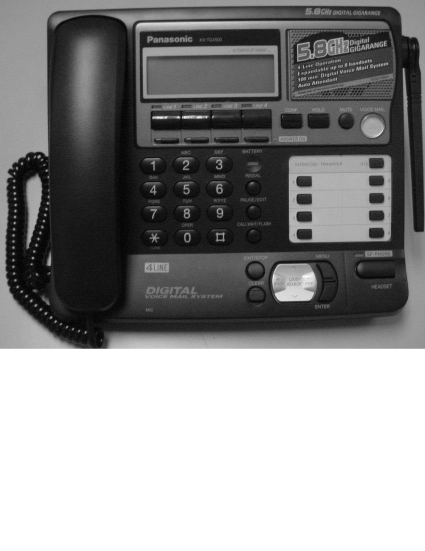
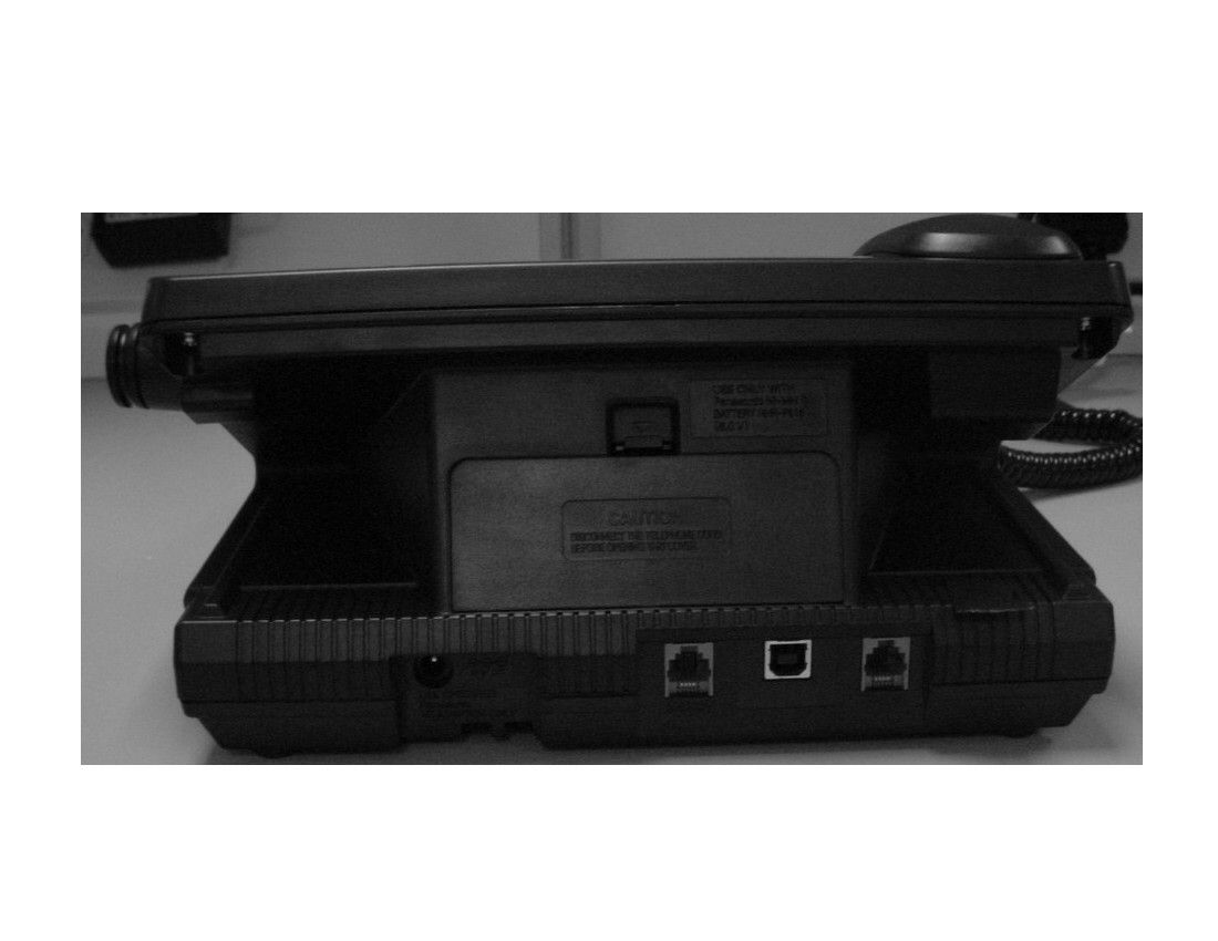
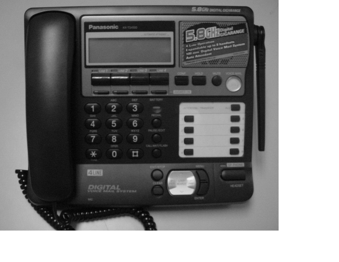
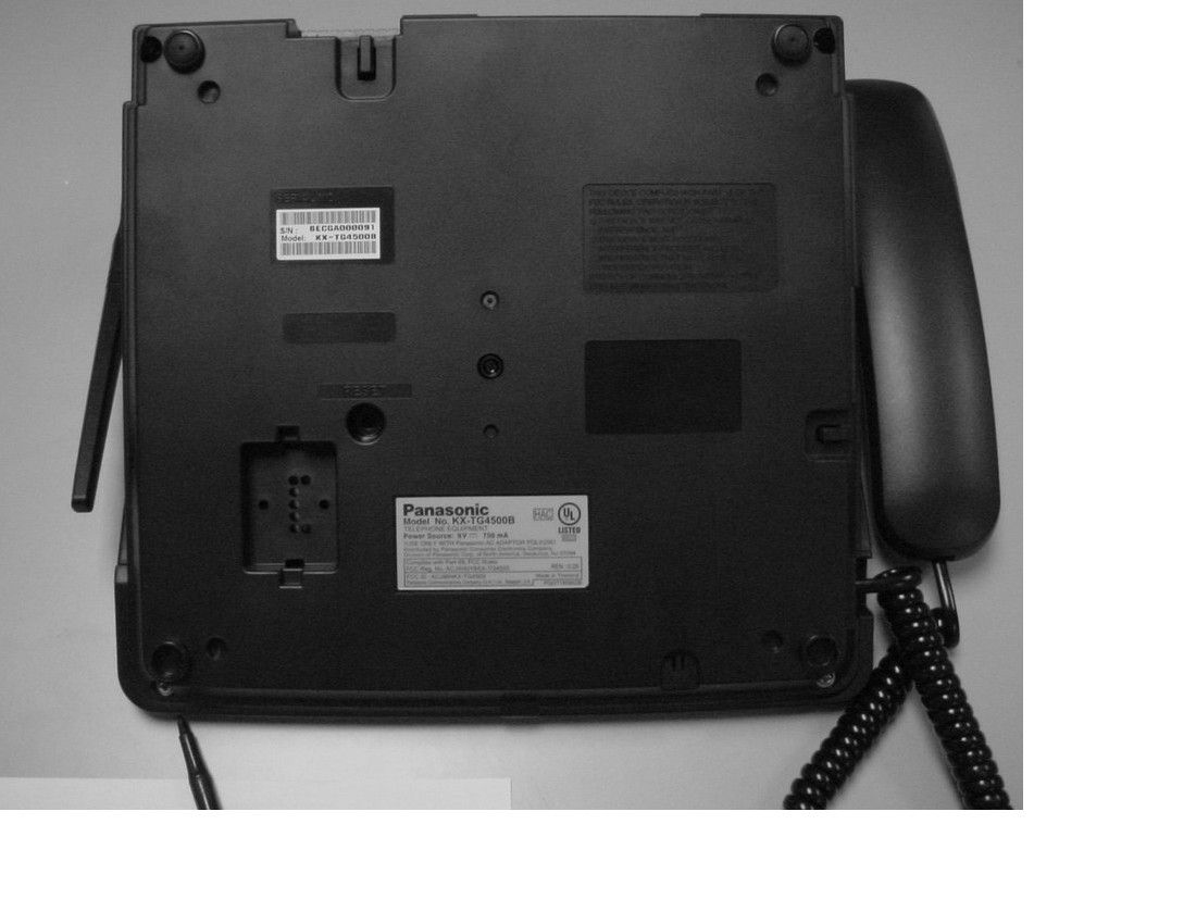
ACJPCCUKKX-TG45004 line 5.8 GHz cordless telephone system
Panasonic Corporation of North America
Click to zoom
Application Details
- Equipment Class
- DTS - Digital Transmission System
- Date of Grant
- Aug 22, 2006
- Application Purpose
- Original Equipment
- Date of Application
- Jul 17, 2006
- Equipment Note
- 4 line 5.8 GHz cordless telephone system
- Frequency Range
- 5760.00000000 - 5840.00000000
- Country
- United States
Documents & Files
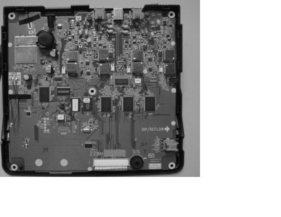
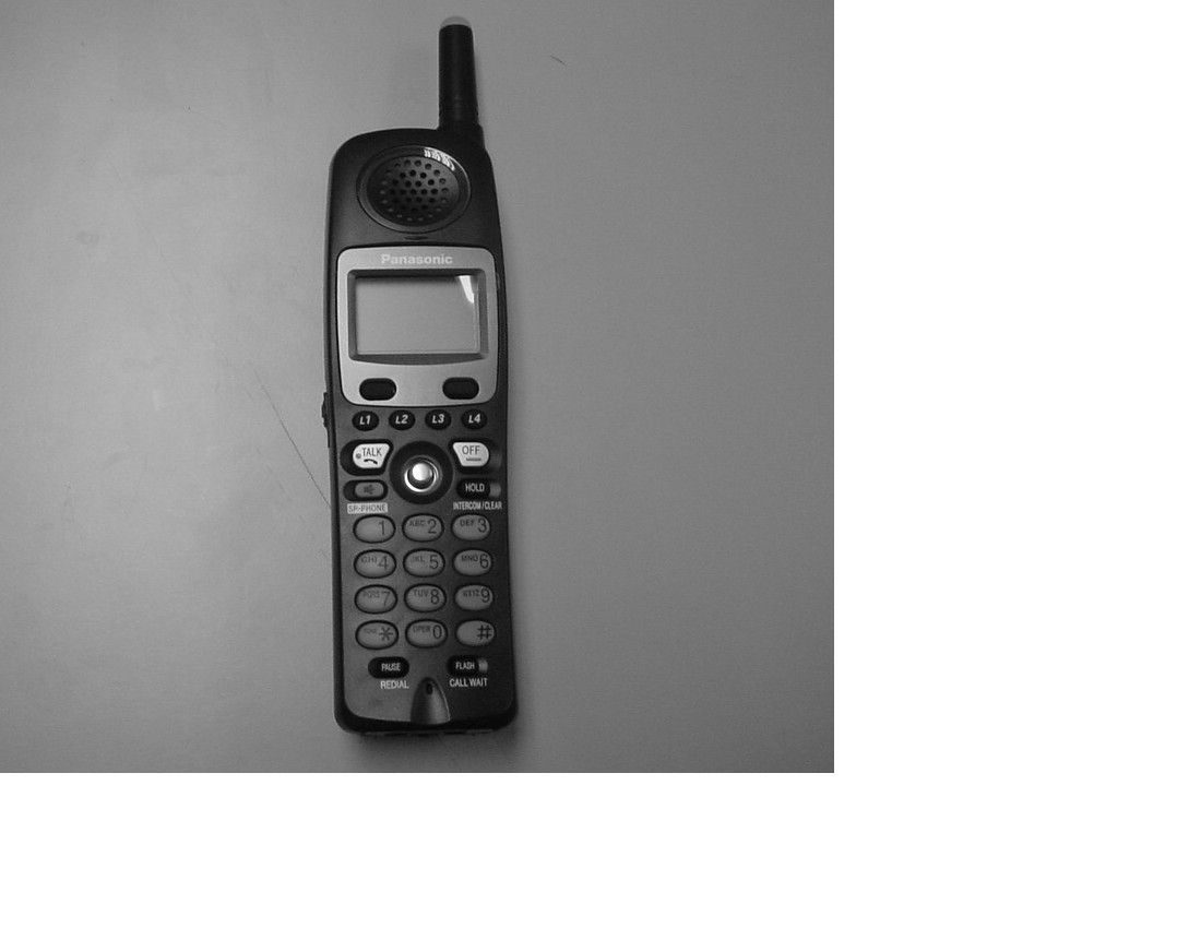
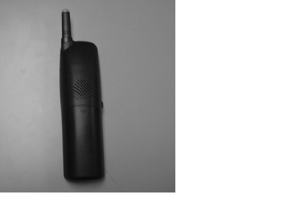
Document Text
Text extracted from the exhibit documents filed with the FCC. Open a document above to read the original.
Users Manual
This unit is compatible with Caller ID. To use this feature you must subscribe to the appropriate service offered by your service provider. Please read these Operating Instructions before using the unit and save them for future reference. For assistance, visit our website: http://www.panasonic.com/phonehelp for customers in the U.S.A. or Puerto Rico. Charge the cordless handset battery for 7 hours before initial use. 5.8 GHz Expandable Digital Cordless Phone System Model No. KX-TG4500 Operating Instructions S P -P H O NE 1 2 3 4 5 6 7 8 9 0 ANSWER ON E N S P -P H O Table of Contents 2For assistance, please visit http://www.panasonic.com/phonehelp Introduction Accessory information . . . . . . . . . . . . . . 6 Expanding your phone. . . . . . . . . . . . . . 7 Important safety instructions . . . . . . . . . 8 For best performance. . . . . . . . . . . . . . 10 System capabilities. . . . . . . . . . . . . . . . 11 Preparation Installation . . . . . . . . . . . . . . . . . . . . . . 12 Installing the backup battery in the base unit . . . . . . . . . . . . . . . . . . . . . 12 Connecting the base unit handset and AC adaptor . . . . . . . . . . . . . . . . 13 Connecting the line cords . . . . . . . . 14 Connecting the AC adaptor to the charger . . . . . . . . . . . . . . . . . . . . . . 16 If you subscribe to a DSL service . . 16 Installing the battery in the cordless handset . . . . . . . . . . . . . . . 17 Battery charge . . . . . . . . . . . . . . . . 17 Controls and display. . . . . . . . . . . . . . . 19 Controls . . . . . . . . . . . . . . . . . . . . . 19 Using softkeys and navigation keys 22 Displays . . . . . . . . . . . . . . . . . . . . . 24 Setting-up the unit before use . . . . . . . 25 Setting the date and time . . . . . . . . 25 Setting the display language . . . . . . 25 Selecting the line mode . . . . . . . . . 26 Selecting the dialing mode . . . . . . . 26 Registering additional cordless handsets . . . . . . . . . . . . . . . . . . . . . 26 Making/Answering Calls Making calls . . . . . . . . . . . . . . . . . . . . . 29 Answering calls . . . . . . . . . . . . . . . . . . 33 Using additional lines during a conversation . . . . . . . . . . . . . . . . . . . 35 Intercom. . . . . . . . . . . . . . . . . . . . . . . . 36 Making an intercom call . . . . . . . . . 36 Answering intercom calls . . . . . . . . 36 Transferring a call. . . . . . . . . . . . . . . . . 37 Placing a call on hold. . . . . . . . . . . . . . 38 Swapping between two external calls . 38 Conference calls. . . . . . . . . . . . . . . . . . 39 Conference with two external calls using the base unit . . . . . . . . . . . . . 39 Conference with two external calls using the cordless handset . . . . . . . 39 Conference with an external call and cordless handset (using the base unit) . . . . . . . . . . . . . . . . . . . . 39 Conference with an external call and base unit or another cordless handset (using a cordless handset) . . . . . . . . . . . . . . 40 Useful features during a call. . . . . . . . . 40 Joining in a conversation . . . . . . . . . 40 Call privacy . . . . . . . . . . . . . . . . . . . 40 Recording a conversation . . . . . . . . 41 Muting your conversation . . . . . . . . 41 Using the PAUSE key (for PBX line or long distance calls) . . . . . . . . 42 Using the FLASH key . . . . . . . . . . . 42 For call waiting service users . . . . . 42 Temporary tone dialing . . . . . . . . . . 43 Phonebook Using the Phonebook. . . . . . . . . . . . . . 44 Storing names and numbers in the Phonebook . . . . . . . . . . . . . . . . . . . 44 Finding and calling a Phonebook item . . . . . . . . . . . . . . . . . . . . . . . . . 45 Editing Phonebook items . . . . . . . . 47 Assigning a ringer pattern to a Phonebook item . . . . . . . . . . . . . . . 47 Erasing Phonebook items . . . . . . . . 48 Chain dial . . . . . . . . . . . . . . . . . . . 48 Caller ID Service Using caller ID service . . . . . . . . . . . . . 49 Caller list. . . . . . . . . . . . . . . . . . . . . . . . 50 Viewing and calling back using the caller list . . . . . . . . . . . . . . . . . . . . . 50 Editing a caller’s phone number before calling back . . . . . . . . . . . . . 51 Storing caller information in the Phonebook . . . . . . . . . . . . . . . . . . . 51 Erasing caller information . . . . . . . . 52 Voice Mail System Voice Mail System . . . . . . . . . . . . . . . . 53 Setting the mailbox password . . . . . 53 Listening to messages from the base unit . . . . . . . . . . . . . . . . . . . . . 54 Listening to messages with the cordless handset . . . . . . . . . . . . . . . 57 Creating and sending messages . . . 59 Transferring a call to a personal mailbox . . . . . . . . . . . . . . . . . . . . . . 60 Checking the remaining recording time and number of messages . . . . 61 Erasing all messages stored in a mailbox . . . . . . . . . . . . . . . . . . . . . . 61 User greetings . . . . . . . . . . . . . . . . . 62 Personal greetings . . . . . . . . . . . . . 62 Table of Contents For assistance, please visit http://www.panasonic.com/phonehelp3 Turning the cordless handset answer mode on or off . . . . . . . . . . 64 Remote access. . . . . . . . . . . . . . . . . . . 65 Remote access Accessing the voice mail system remotely . . . . . . . . . . . . . . . . . . . . . 65 Automated Attendant System Automated Attendant System. . . . . . . . 68 How the Automated Attendant System works . . . . . . . . . . . . . . . . . 68 Setting the Automated Attendant System . . . . . . . . . . . . . . . . . . . . . . 69 Call transfer status . . . . . . . . . . . . . 71 Call operator status . . . . . . . . . . . . . 72 Answering System Setting the Answering System . . . . . . 73 Turning on the Answering System . 73 Defining the number of rings . . . . . . 73 Selecting the pre-recorded greeting message . . . . . . . . . . . . . . 73 Recording a greeting message . . . . 74 Selecting a greeting message . . . . . 74 Changing a recorded message . . . . 74 Erasing a greeting message . .…
Text truncated - open the document above for the full version.
Attestation Statements
The errors that need changing on the 731 form are: • The equipment code needs changing from CYY to DSS. • The transmitter operations frequency reads 3850-5725MHz and the RF 1.0 watt when it should be transmitters operation frequency 5725~5850 MHz with base unit RF output power 0.066 watts and handset unit RF output power 0.00484 watts
Attestation Statements
Hi Andrew, With reference to correspondence 31393 regarding the issue spurious radiated emissions please find an explanation of why this has occurred: We have not applied 15.231 to this product. The EUT uses a TDMA modulation technique that means its fundamental frequency only dwells on each frequency segment for 3.98ms in every 100ms. The guidance notes from the FCC issued specifically for testing this kind of digital transmission system allow for a pulse desensitization calculation to be made and the peak level adjusted to reflect this. The guidance notes actually refer to 'duty cycle correction' and this text has found it's way into the report so this may have confused the FCC assessor. This is in the FCC technical guidance note for information, see section 15,247c (2). The correction calculation is detailed in annex I of the test report. Regards Michael Gaukroger Approvals Specialist
ID Label/Location Info
26-April-2006 2:1 Reg. No. US : ACJW406BKX-TG4500 REN : 0.6B 61.0 (2:1) 29.5 (2:1) Distributed by Panasonic Consumer Electronics Company, Division of Panasonic Corp. of North America, Secaucus, NJ 07094 FCC CODE AND UL NO. ADDED, P/N CHANGE 26-04-06 ZB JR PQGT18590ZB PQGT18590ZC PQGT18590ZC 03-07-06 TEXT MODIFIED, P/N CHANGE ZB JR 8 B 2 2 INFO. TECH. EQUIP. FCC ID : ACJPCCUKKX-TG4500 ZB JR REG. NO. CHANGED, REN CHANGED 05-07-06 3
RF Exposure Info
DAT-P-152/98-01 SAR Report, Nemko_6620_570_FCC_5800_KX-TG4500_2 Page 1 of 35 Report Dosimetric Assessment of the Portable Device Panasonic KX-TG4500 (FCC ID: ACJPCCUKKX-TG4500) According to the FCC Requirements January 26, 2006 IMST GmbH Carl-Friedrich-Gauß-Str. 2 D-47475 Kamp-Lintfort Customer RTX Telecom A/S Stroemmen 6 DK-9400 Norresundby The test results only relate to the items tested. This report shall not be reproduced except in full without the written approval of the testing laboratory. dasy_report_fcc_5GHz_1.0.doc/23.11.2005/CH SAR Report, Nemko_6620_570_FCC_5800_KX-TG4500_2 Page 2 of 35 dasy_report_fcc_5GHz_1.0.doc/23.11.2005/CH Executive Summary The KX-TG4500 is a cordless phone (Portable Device) from Panasonic operating in the 5,8 GHz frequency range. The device has two antennas which are working as a diversity system. The objective of the measurements done by IMST was the dosimetric assessment of one device in a worst case setup, the handset was set to use one specific antenna during the measurement and using dual slot diversity (2 channels a the same time). The examinations have been carried out with the dosimetric assessment system „DASY4“. The measurements were made according to the Supplement C to OET Bulletin 65 of the Federal Communications Commission (FCC) Guidelines [OET 65] for evaluating compliance of mobile and portable devices with FCC limits for human exposure (general population) to radiofrequency emissions. All measurements have been performed in accordance to the recommendations given by SPEAG. The Panasonic KX-TG4500 cordless phone (FCC ID: ACJPCCUKKX-TG4500) is in compliance with the Federal Communications Commission (FCC) Guidelines [OET 65] for uncontrolled exposure. The phone was tested in addition to the head positions in the following configuration: Body worn with the following accessories: • headset and belt clip prepared by: ........................................... reviewed by: ..................................... Alexander Rahn André van den Bosch test engineer quality assurance engineer IMST GmbH Carl-Friedrich-Gauß-Straße 2 D-47475 Kamp-Lintfort Tel. +49- 2842-981 378 Fax +49- 2842-981 399 email: [email protected] SAR Report, Nemko_6620_570_FCC_5800_KX-TG4500_2 Page 3 of 35 dasy_report_fcc_5GHz_1.0.doc/23.11.2005/CH Table of Contents 1 SUBJECT OF INVESTIGATION.................................................................................................................... 4 2 THE IEEE STANDARD C95.1 AND THE FCC EXPOSURE CRITERIA................................................. 4 2.1 DISTINCTION BETWEEN EXPOSED POPULATION, DURATION OF EXPOSURE AND FREQUENCIES........... 4 2.2 DISTINCTION BETWEEN MAXIMUM PERMISSIBLE EXPOSURE AND SAR LIMITS....................................... 5 2.3 SAR LIMIT.................................................................................................................................................. 5 3 THE FCC MEASUREMENT PROCEDURE................................................................................................. 6 3.1 GENERAL REQUIREMENTS......................................................................................................................... 6 3.2 DEVICE OPERATING NEXT TO A PERSON’S EAR....................................................................................... 6 4 BODY-WORN CONFIGURATIONS.............................................................................................................. 9 4.1 POC (PTT) POSITION...............................................................................................................................9 4.2 PHANTOM REQUIREMENTS...................................................................................................................... 10 4.3 TEST TO BE PERFORMED......................................................................................................................... 10 5 THE MEASUREMENT SYSTEM................................................................................................................. 10 5.1 PHANTOM................................................................................................................................................. 12 5.2 PROBE...................................................................................................................................................... 12 5.3 MEASUREMENT PROCEDURE.................................................................................................................. 13 5.4 UNCERTAINTY ASSESSMENT................................................................................................................... 14 6 SAR RESULTS............................................................................................................................................... 15 7 EVALUATION................................................................................................................................................. 17 8 APPENDIX....................................................................................................................................................... 19 8.1 ADMINISTRATIVE DATA............................................................................................................................ 19 8.2 DEVICE UNDER TEST AND TEST CONDITIONS......................................................................................... 19 8.3 TISSUE RECIPES...................................................................................................................................... 19 8.4 MATERIAL PARAMETERS......................................................................................................................... 20 8.5 SIMPLIFIED PERFORMANCE CHECKING................................................................................................... 20 8.6 ENVIRONMENT....................................................................................…
Text truncated - open the document above for the full version.
RF Exposure Info
DAT-P-152/98-01 SAR Report, Nemko_6620_570_FCC_5.8GHz_SAR Plots_KX-TG4500_2 Page 1 of 14 Appendix for the Report Dosimetric Assessment of the Panasonic KX-TG4500 (FCC ID: ACJPCCUKKX-TG4500) According to the FCC Requirements SAR Distribution Plots January 26, 2006 IMST GmbH Carl-Friedrich-Gauß-Str. 2 D-47475 Kamp-Lintfort Customer RTX Telecom A/S Stroemmen 6 DK-9400 Norresundby The test results only relate to the items tested. This report shall not be reproduced except in full without the written approval of the testing laboratory. dasy_report_fcc_WLAN_plots_1.0.doc/06.12.2005/AR SAR Report, Nemko_6620_570_FCC_5.8GHz_SAR Plots_KX-TG4500_2 Page 2 of 14 dasy_report_fcc_1900_plots_1.1.doc/08.07.2005/CH Table of Contents 1 SAR DISTRIBUTION PLOTS, WLAN 5800 MHZ, HEAD, ANTENNA 1................................................. 3 2 SAR DISTRIBUTION PLOTS, WLAN 5800 MHZ, HEAD, ANTENNA 2................................................. 7 3 SAR DISTRIBUTION PLOTS, 5800 MHZ, BODY WITH HEADSET, ANTENNA 1............................ 11 4 SAR DISTRIBUTION PLOTS, 5800 MHZ, BODY WITH HEADSET, ANTENNA 2............................ 12 5 SAR Z-AXIS SCANS (VALIDATION)......................................................................................................... 13 6 SAR Z-AXIS SCANS (MEASUREMENTS)................................................................................................ 14 SAR Report, Nemko_6620_570_FCC_5.8GHz_SAR Plots_KX-TG4500_2 Page 3 of 14 dasy_report_fcc_1900_plots_1.1.doc/08.07.2005/CH 1 SAR Distribution Plots, WLAN 5800 MHz, Head, Antenna 1 Test Laboratory: IMST GmbH, DASY Blue (I); File Name: A1b5lm_1.da4 DUT: Panasonic KX-TG4500; Type: KX-TG4500; Program Name: Cheek Left Communication System: 5.8 GHz; Frequency: 5787.94 MHz;Duty Cycle: 1:12.5 Medium parameters used (interpolated): f = 5787.94 MHz; σ = 5.41 mho/m; ε r = 35.5; ρ = 1000 kg/m 3 Phantom section: Left Section DASY4 Configuration: - Probe: EX3DV4 - SN3536; ConvF(4.73, 4.73, 4.73); Calibrated: 23.09.2005 - Sensor-Surface: 2.5mm (Mechanical Surface Detection) - Electronics: DAE4 Sn631; Calibrated: 07.07.2005 - Phantom: SAM Glycol 1176; Type: Speag; Serial: 1176 - Measurement SW: DASY4, V4.6 Build 19; Postprocessing SW: SEMCAD, V1.8 Build 159 Cheek Left/Area Scan (8x24x1): Measurement grid: dx=10mm, dy=10mm Maximum value of SAR (measured) = 0.180 mW/g Cheek Left/Zoom Scan (8x8x8)/Cube 0: Measurement grid: dx=4.3mm, dy=4.3mm, dz=3mm Reference Value = 1.95 V/m; Power Drift = 0.129 dB Peak SAR (extrapolated) = 0.435 W/kg SAR(1 g) = 0.114 mW/g; SAR(10 g) = 0.045 mW/g Maximum value of SAR (measured) = 0.178 mW/g Cheek Left/Zoom Scan (8x8x8)/Cube 1: Measurement grid: dx=4.3mm, dy=4.3mm, dz=3mm Reference Value = 1.95 V/m; Power Drift = 0.129 dB Peak SAR (extrapolated) = 0.278 W/kg SAR(1 g) = 0.051 mW/g; SAR(10 g) = 0.020 mW/g Maximum value of SAR (measured) = 0.095 mW/g Fig. 1: SAR distribution for Panasonic KX-TG4500 handset, channel 18/28, cheek position, left side of head (January 23, 2006; Ambient Temperature: 21.5°C; Liquid Temperature: 20.5°C). SAR Report, Nemko_6620_570_FCC_5.8GHz_SAR Plots_KX-TG4500_2 Page 4 of 14 dasy_report_fcc_1900_plots_1.1.doc/08.07.2005/CH Test Laboratory: IMST GmbH, DASY Blue (I); File Name: A1b5lm_2.da4 DUT: Panasonic KX-TG4500; Type: KX-TG4500; Program Name: Tilted Left Communication System: 5.8 GHz; Frequency: 5787.94 MHz;Duty Cycle: 1:12.5 Medium parameters used (interpolated): f = 5787.94 MHz; σ = 5.41 mho/m; ε r = 35.5; ρ = 1000 kg/m 3 Phantom section: Left Section DASY4 Configuration: - Probe: EX3DV4 - SN3536; ConvF(4.73, 4.73, 4.73); Calibrated: 23.09.2005 - Sensor-Surface: 2.5mm (Mechanical Surface Detection) - Electronics: DAE4 Sn631; Calibrated: 07.07.2005 - Phantom: SAM Glycol 1176; Type: Speag; Serial: 1176 - Measurement SW: DASY4, V4.6 Build 19; Postprocessing SW: SEMCAD, V1.8 Build 159 Cheek Left/Area Scan (8x24x1): Measurement grid: dx=10mm, dy=10mm Maximum value of SAR (measured) = 0.347 mW/g Cheek Left/Zoom Scan (8x8x8)/Cube 0: Measurement grid: dx=4.3mm, dy=4.3mm, dz=3mm Reference Value = 2.04 V/m; Power Drift = 0.190 dB Peak SAR (extrapolated) = 0.805 W/kg SAR(1 g) = 0.213 mW/g; SAR(10 g) = 0.078 mW/g Maximum value of SAR (measured) = 0.337 mW/g Fig. 2: SAR distribution for Panasonic KX-TG4500 handset, channel 18/28, tilted position, left side of head (January 23, 2006; Ambient Temperature: 21.5° C; Liquid Temperature : 20.5° C). SAR Report, Nemko_6620_570_FCC_5.8GHz_SAR Plots_KX-TG4500_2 Page 5 of 14 dasy_report_fcc_1900_plots_1.1.doc/08.07.2005/CH Test Laboratory: IMST GmbH, DASY Blue (I); File Name: A1b5rm_1.da4 DUT: Panasonic KX-TG4500; Type: KX-TG4500; Program Name: Cheek Right Communication System: 5.8 GHz; Frequency: 5787.94 MHz;Duty Cycle: 1:12.5 Medium parameters used (interpolated): f = 5787.94 MHz; σ = 5.41 mho/m; ε r = 35.5; ρ = 1000 kg/m 3 Phantom section: Right Section DASY4 Configuration: - Probe: EX3DV4 - SN3536; ConvF(4.73, 4.73, 4.73); Calibrated: 23.09.2005 - Sensor-Surface: 2.5mm (Mechanical Surface Detection) - Electronics: DAE4 Sn631; Calibrated: 07.07.2005 - Phantom: SAM Glycol 1176; Type: Speag; Serial: 1176 - Measurement SW: DASY4, V4.6 Build 19; Postprocessing SW: SEMCAD, V1.8 Build 159 Cheek Right/Area Scan (6x16x1): Measurement grid: dx=15mm, dy=15mm Maximum value of SAR (measured) = 0.122 mW/g Cheek Right/Zoom Scan (8x8x8)/Cube 0: Measurement grid: dx=4.3mm, dy=4.3mm, dz=3mm Reference Value = 1.98 V/m; Power Drift = -0.180 dB Peak SAR (extrapolated) = 0.426 W/kg SAR(1 g) = 0.063 mW/g; SAR(10 g) = 0.023 mW/g Maximum value of SAR (measured) = 0.126 mW/g Cheek Right/Zoom Scan (8x8x8)/Cube 1: Measurement grid: dx=4.3mm, dy=4.3mm, dz=3mm Reference Value = 1.98 V/m; Power Drift = -0.180 dB Peak SAR (extrapolated) = 0.204 W/kg SAR(1 g) = 0.062 mW/g; SAR(10 g) = 0.026 mW/g Maximum value of SAR (measured) = 0.115 mW/g Fig. 3: SAR distribution for Panasonic KX-TG4500 handset, channel 18/28, cheek position, right side of head (January 23, 2006; Amb…
Text truncated - open the document above for the full version.
RF Exposure Info
DAT-P-152/98-01 SAR Report, Nemko_6620_570_FCC_5.8GHz_CalData_KX-TG4500_2 dasy_report_fcc_850_1900_cal_data_2.0.doc/08.01.2005/CH Appendix for the Report Dosimetric Assessment of the Panasonic KX-TG4500 (FCC ID: ACJPCCUKKX-TG4500) According to the FCC Requirements Calibration Data January 26, 2006 IMST GmbH Carl-Friedrich-Gauß-Str. 2 D-47475 Kamp-Lintfort Customer RTX Telecom A/S Stroemmen 6 DK-9400 Norresundby This report shall not be reproduced except in full without the written approval of the testing laboratory.
Test Report
TRL COMPLIANCE LTD M OSS VIEW NIPE LANE UP HOLLAND WEST LANCASHIRE WN8 9PY UNITED KINGDOM T ELEPHONE +44 (0)1695 556666 FAX +44 (0)1695 557077 E-MAIL [email protected] www.trlcompliance.com 0728 TEST REPORT NO: RU1252/7073 COPY NO: 1 ISSUE NO: 1 FCC ID: ACJPCCUKKX-TG4500 REPORT ON THE CERTIFICATION TESTING OF A PANASONIC COMMUNICATIONS COMPANY (UK) Ltd. KX-TGA450B WITH RESPECT TO THE FCC RULES CFR 47, PART 15.247 February 2006 INTENTIONAL RADIATOR SPECIFICATION TEST DATE: 19 th – 21 st June 2006 TESTED BY: D Winstanley APPROVED BY: P Green Product Manager DATE: 29 th June 2006 Distribution: Copy Nos: 1. PANASONIC COMMUNICATIONS COMPANY (UK) Ltd. 2. FCC Evaluation Laboratories 3. TRL Compliance Ltd THIS DOCUMENT MAY BE REPRODUCED ONLY IN ITS ENTIRETY AND WITHOUT CHANGE RU1252/7073 Page 2 of 49 CONTENTS PAGE CERTIFICATE OF CONFORMITY & COMPLIANCE 3 APPLICANT’S SUMMARY 4 EQUIPMENT TEST CONDITIONS 5 TESTS REQUIRED 5 TEST RESULTS 6-13 ANNEX PHOTOGRAPHS A PHOTOGRAPH No. 1: Test setup PHOTOGRAPH No. 2: Transmitter top overview PHOTOGRAPH No. 3: Transmitter bottom overview PHOTOGRAPH No. 4: Transmitter overview PHOTOGRAPH No. 5: Main PCB LCD and Keypad Side PHOTOGRAPH No. 6: Main PCB Component and RF Side PHOTOGRAPH No. 7: Main PCB RF Side Can Removed APPLICANT’S SUBMISSION OF DOCUMENTATION LIST B 6dB BAND WIDTH PLOT C RADIATED POWER SPECTRAL DENSITY D RADIATED SPURIOUS EMISSIONS – TX E RADIATED SPURIOUS EMISSIONS – BANDEDGE F POWER LINE CONDUCTED EMISSIONS G RADIATED SPURIOUS EMISSIONS – RX H DUTY CYCLE I TEST EQUIPMENT CALIBRATION DETAILS J MEASUREMENT UNCERTAINTY K Notes: 1. Component failure during test YES NO [ ] [X] 2. If Yes, details of failure: 3. The facilities used for the testing of the product contain in this report are FCC Listed. 4. The contents of the attached applicants declarations and other supplied information are not covered by the scope of this laboratory’s UKAS or FCC accreditations’ and is provided in good faith. RU1252/7073 Page 3 of 49 CERTIFICATE OF CONFORMITY & COMPLIANCE FCC IDENTITY: ACJPCCUKKX-TG4500 PURPOSE OF TEST: Certification TEST SPECIFICATION: FCC RULES CFR 47, Part 15.247 February 2006 TEST RESULT: Compliant to Specification EQUIPMENT UNDER TEST: KX-TGA450B EQUIPMENT SERIAL No: 6ECGA000088 EQUIPMENT TYPE: Cordless Telephone CARRIER EMISSION: 0.00484 Watts ANTENNA TYPE: Integral Diversity Antenna GAIN ANTENNA: 3dBi Maximum Gain Antenna BAND OF OPERATION: 5725 MHz - 5850 MHz CHANNEL SPACING: 2.592 MHz NUMBER OF CHANNELS: 47 FREQUENCY GENERATION: SAW Resonator [ ] Crystal [ ] Synthesiser [X] MODULATION METHOD: Amplitude [ ] Digital [X] Angle [ ] POWER SOURCE(s): +3.6Vdc TEST DATE(s): 19 th – 21 st June 2006 ORDER No(s): 40020182 APPLICANT: Panasonic Communications Company (UK) Ltd. ADDRESS: Pencarn Way Duffryn Newport South Wales NP10 8YE TESTED BY: D Winstanley APPROVED BY: P Green Product Manager RU1252/7073 Page 4 of 49 APPLICANT’S SUMMARY EQUIPMENT UNDER TEST (EUT): KX-TGA450B EQUIPMENT TYPE: Cordless Telephone SERIAL NUMBER OF EUT: 6ECGA000088 PURPOSE OF TEST: Certification TEST SPECIFICATION(s): FCC RULES CFR 47, Part 15.247 February 2006 TEST RESULT: COMPLIANT Yes No [X] [ ] APPLICANT’S CATEGORY: MANUFACTURER IMPORTER DISTRIBUTOR TEST HOUSE AGENT [X] [ ] [ ] [ ] [ ] APPLICANT’S ORDER No(s): 40020182 APPLICANT’S CONTACT PERSON(s): Mr Keith Jones E-mail address: [email protected] APPLICANT: Panasonic Communications Company (UK) Ltd. ADDRESS: Pencarn Way Duffryn Newport South Wales NP10 8YE TEL: +44 (0) 1633 653843 FAX: +44 (0) 1633 816363 MANUFACTURER: Panasonic Communications Company (UK) Ltd. EUT(s) COUNTRY OF ORIGIN: United Kingdom TEST LABORATORY: TRL Compliance UKAS ACCREDITATION No: 0728 TEST DATE(s) 19 th – 21 st June 2006 TEST REPORT No: RU1252/7073 RU1252/7073 Page 5 of 49 EQUIPMENT TEST / EXAMINATIONS REQUIRED 1. TEST/EXAMINATION RULE PART DETECTOR APPLICABILITY Intentional Emission Frequency: 15.247(b) Peak Yes Intentional Emission Field Strength: - - No Intentional Emission Band Occupancy 6dB: 15.247 (a) Peak Yes Intentional Emission ERP (mW): 15.247 (b) Peak Yes Spurious Emissions – Conducted: - - No Spurious Emissions – Radiated <1000MHz: 15.209 Quasi Peak Yes (note 1) Spurious Emissions – Radiated >1000MHz: 15.209 Average Yes (note 1) Spectral Power Density: 15.247 (e) Peak Yes Spurious Emissions – Power Line TX: 15.207 Quasi Peak Average Yes Spurious Emissions – Power Line RX: 15.107 Quasi Peak Average Yes Maximum Frequency of Search: 15.33 - Yes Antenna Arrangements Integral: 15.203 - Yes Antenna Arrangements External Connector: 15.204 - Yes Restricted Bands: 15.205 - Yes Extrapolation Factor: 15.31(f) - Yes Note 1:The unit has integral antennas, therefore all measurements were performed radiated. 2. Emission Designator: 1M04F1D 3. Duty Cycle: <8% 4. Transmitter bit or pulse rate and level: 1152kbps 5. Temperatures: Ambient (Tnom) 21 o C 6. Supply Voltages: Vnom +3.6Vdc Note: Vnom voltages are as stated above unless otherwise shown on the test report page Single channel [ ] Two channel [ ] 7. Equipment Category: Multi-channel [X] Narrowband [ ] Wideband [X] 8. Channel Allocation: RU1252/7073 Page 6 of 49 TRANSMITTER TESTS TRANSMITTER 6dB BANDWIDTH – RADIATED - PART 15.247(A)(2) Ambient temperature = 18 o C(<1GHz) Relative humidity = 58% (<1GHz) Conditions = Semi Anechoic chamber Supply voltage = +3.6Vdc Diagram Frequency (MHz) Channel Measured Bandwidth Limit 5728.320 0 977.565 kHz >500kHz 5787.936 23 984.577 kHz >500kHz 5847.552 46 1041.667 kHz >500kHz Notes: 1 For analyser plots of channel 46 antenna 1 see annex C. Test Method: 1 The EUT was set to top middle and bottom operating frequencies 2 The bandwidth was measured on the antenna with the strongest output power 3 The 6dB bandwidth was recorded with the EUT actively transmitting data. TYPE OF EQUIPMENT MAKER/ SUPPLIER MODEL No SERIAL No TRL No ACTUAL EQUIPMENT USED SPECTRUM ANALYSER R&S FSU46 200034 UH281 X HORN ANTENNA EMCO 3115 9010-3580 138 X CABLE ROSENBERGER RTK161-G…
Text truncated - open the document above for the full version.
Test Report
TRL COMPLIANCE LTD M OSS VIEW NIPE LANE UP HOLLAND WEST LANCASHIRE WN8 9PY UNITED KINGDOM T ELEPHONE +44 (0)1695 556666 FAX +44 (0)1695 557077 E-MAIL [email protected] www.trlcompliance.com 0728 TEST REPORT NO: RU1252/7074 COPY NO: 1 ISSUE NO: 1 FCC ID: ACJPCCUKKX-TG4500 REPORT ON THE CERTIFICATION TESTING OF A PANASONIC COMMUNICATIONS COMPANY (UK) Ltd. KX-TG4500 WITH RESPECT TO THE FCC RULES CFR 47, PART 15.247 February 2006 INTENTIONAL RADIATOR SPECIFICATION TEST DATE: 19 th – 21 st June 2006 TESTED BY: D Winstanley APPROVED BY: P Green Product Manager DATE: 29 th June 2006 Distribution: Copy Nos: 1. PANASONIC COMMUNICATIONS COMPANY (UK) Ltd. 2. FCC Evaluation Laboratories 3. TRL Compliance Ltd THIS DOCUMENT MAY BE REPRODUCED ONLY IN ITS ENTIRETY AND WITHOUT CHANGE RU1252/7074 Page 2 of 47 CONTENTS PAGE CERTIFICATE OF CONFORMITY & COMPLIANCE 3 APPLICANT’S SUMMARY 4 EQUIPMENT TEST CONDITIONS 5 TESTS REQUIRED 5 TEST RESULTS 6-13 ANNEX PHOTOGRAPHS A PHOTOGRAPH No. 1: Test setup PHOTOGRAPH No. 2: Transmitter Top View PHOTOGRAPH No. 3: Transmitter Rear View PHOTOGRAPH No. 4: Transmitter Rear View Cover Removed PHOTOGRAPH No. 5: Main PCB Track Side PHOTOGRAPH No. 6: Main PCB Component Side PHOTOGRAPH No. 7: Main PCB Component Side Can Removed APPLICANT’S SUBMISSION OF DOCUMENTATION LIST B 6dB BAND WIDTH PLOT C RADIATED POWER SPECTRAL DENSITY D RADIATED SPURIOUS EMISSIONS – TX E RADIATED SPURIOUS EMISSIONS – BANDEDGE F POWER LINE CONDUCTED EMISSIONS G RADIATED SPURIOUS EMISSIONS – RX H DUTY CYCLE I TEST EQUIPMENT CALIBRATION DETAILS J MEASUREMENT UNCERTAINTY K Notes: 1. Component failure during test YES NO [ ] [X] 2. If Yes, details of failure: 3. The facilities used for the testing of the product contain in this report are FCC Listed. 4. The contents of the attached applicants declarations and other supplied information are not covered by the scope of this laboratory’s UKAS or FCC accreditations’ and is provided in good faith. RU1252/7074 Page 3 of 47 CERTIFICATE OF CONFORMITY & COMPLIANCE FCC IDENTITY: ACJPCCUKKX-TG4500 PURPOSE OF TEST: Certification TEST SPECIFICATION: FCC RULES CFR 47, Part 15.247 February 2006 TEST RESULT: Compliant to Specification EQUIPMENT UNDER TEST: KX-TG4500 EQUIPMENT SERIAL No: 6ECGA000088 EQUIPMENT TYPE: Cordless Telephone System Base Unit CARRIER EMISSION: 0.066 Watts ANTENNA TYPE: Integral Diversity Antenna GAIN ANTENNA: 5dBi Maximum Gain Antenna BAND OF OPERATION: 5725 MHz - 5850 MHz CHANNEL SPACING: 2.592 MHz NUMBER OF CHANNELS: 47 FREQUENCY GENERATION: SAW Resonator [ ] Crystal [ ] Synthesiser [X] MODULATION METHOD: Amplitude [ ] Digital [X] Angle [ ] POWER SOURCE(s): +110Vac TEST DATE(s): 19 th – 21 st June 2006 ORDER No(s): 40020182 APPLICANT: Panasonic Communications Company (UK) Ltd. ADDRESS: Pencarn Way Duffryn Newport South Wales NP10 8YE TESTED BY: D Winstanley APPROVED BY: P Green Product Manager RU1252/7074 Page 4 of 47 APPLICANT’S SUMMARY EQUIPMENT UNDER TEST (EUT): KX-TG4500 EQUIPMENT TYPE: Cordless Telephone System Base Unit SERIAL NUMBER OF EUT: 6ECGA000088 PURPOSE OF TEST: Certification TEST SPECIFICATION(s): FCC RULES CFR 47, Part 15.247 February 2006 TEST RESULT: COMPLIANT Yes No [X] [ ] APPLICANT’S CATEGORY: MANUFACTURER IMPORTER DISTRIBUTOR TEST HOUSE AGENT [X] [ ] [ ] [ ] [ ] APPLICANT’S ORDER No(s): 40020182 APPLICANT’S CONTACT PERSON(s): Mr Keith Jones E-mail address: [email protected] APPLICANT: Panasonic Communications Company (UK) Ltd. ADDRESS: Pencarn Way Duffryn Newport South Wales NP10 8YE TEL: +44 (0) 1633 653843 FAX: +44 (0) 1633 816363 MANUFACTURER: Panasonic Communications Company (UK) Ltd. EUT(s) COUNTRY OF ORIGIN: United Kingdom TEST LABORATORY: TRL Compliance UKAS ACCREDITATION No: 0728 TEST DATE(s): 19 th – 21 st June 2006 TEST REPORT No: RU1252/7074 RU1252/7074 Pa…
Text truncated - open the document above for the full version.
Contact Information
Applicant
Ben Botros(Manager - Regulatory & Compliance)
Technical Contact
Panasonic CorporationRichard Mullen
[email protected]201-348-7758
One Panasonic Way 4B-8 · Secaucus, New Jersey · United States
Non-Technical Contact
Panasonic CorporationRichard Mullen
[email protected]201-348-7758
Test Firm
TRL Compliance LtdJohn Charters
Technical Specifications
| # | Rule Parts | Frequency Range | Power Output |
|---|---|---|---|
| 2 | 15C | 5.76 GHz - 5.84 GHz | 66.00 mW |
Other Applications from Panasonic Corporation of North America
ACJ-EAH-A1000
Aug 19, 2026Digital Wireless Stereo Headphones
Equipment Class
DSS - Part 15 Spread Spectrum TransmitterACJ9TGFZVNF3G1
Jun 16, 2026Contactless Smart Card Reader
Equipment Class
DXX - Part 15 Low Power Communication Device Transmitter
ACJ932AM2301
Jan 29, 2025Car AV Control Unit for CDC
Equipment Class
DTS - Digital Transmission SystemACJ96NKX-TGEA60B
Aug 13, 2024DECT Handset
Equipment Class
PUE - Part 15 Unlicensed PCS portable Tx held to earACJ96NKX-TGE630B
Aug 12, 2024DECT Base Unit
Equipment Class
PUB - Part 15 Unlicensed PCS Base Station