ACJT07001Transmitter Module
Panasonic Corporation of North America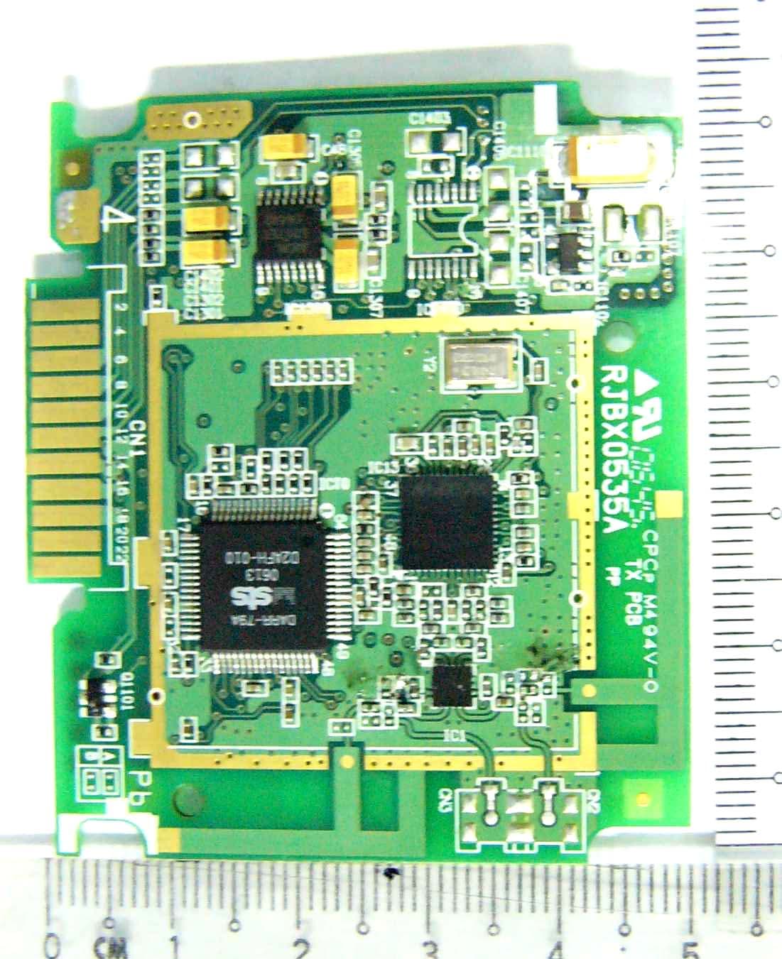
Click to zoom
Application Details
- Equipment Class
- DTS - Digital Transmission System
- Date of Grant
- Dec 17, 2006
- Application Purpose
- Original Equipment
- Date of Application
- Dec 17, 2006
- Equipment Note
- Transmitter Module
- Frequency Range
- 2412.00000000 - 2464.00000000
- Country
- United States
Documents & Files
Document Text
Text extracted from the exhibit documents filed with the FCC. Open a document above to read the original.
Users Manual
P RQTX0047-Y Designed for Panasonic DVD Home Theater Sound Systems that are compatible with the SH-FX65.Dear customerThank you for purchasing this product. For optimum performance and safety, please read these instructions carefully.Before connecting, operating or adjusting this product, please read the instructions completely. Please keep this manual for future reference. Operating Instructions Wireless System and Digital Transmitter Model No. SH-FX65 Table of ContentsIntroduction IMPORTANT SAFETY INSTRUCTIONS................................................ 3Accessory .............................................................................................. 3 Use Setup...................................................................................................... 4 Connections ........................................................................................ 5Making the wireless link ...................................................................... 6 Reference Product service ...................................................................................... 7Maintenance .......................................................................................... 7Troubleshooting guide ............................................................................7Limited Warranty .................................................................................... 8Specifications ....................................................................................... 10 System SH-FX65 Digital transmitter SH-FX65T Wireless system SE-FX65 As an E N ERGY STAR ® Partner, Panasonic has determined thatthis prod u ct meets the E N ERGY STAR ® g u idelines for energy efficiency. RQTX_FX65_En.fm Page 1 Thursday, November 30, 2006 11:52 AM RQTX0047 2 The following mark and symbols are located on bottom of the unit. The lightning flash with arrowhead symbol, within an equilateral triangle, is intended to alert the user to the presence of uninsulated “dangerous voltage” within the product’s enclosure that may be of sufficient magnitude to constitute a risk of el ectric shock to persons. The exclamation point within an equilateral triangle is intended to alert the user to the presence of important operating and maintenance (servicing) instructions in the literature accompanying the appliance. WARNING:TO REDUCE THE RISK OF FIRE, ELECTRIC SHOCK OR PRODUCT DAMAGE, ≥ DO NOT EXPOSE THIS APPARATUS TO RAIN, MOISTURE, DRIPPING OR SPLASHING AND THAT NO OBJECTS FILLED WITH LIQUIDS, SUCH AS VASES, SHALL BE PLACED ON THE APPARATUS. ≥ USE ONLY THE RECOMMENDED ACCESSORIES. ≥ DO NOT REMOVE THE COVER (OR BACK); THERE ARE NO USER SERVICEABLE PARTS INSIDE. REFER SERVICING TO QUALIFIED SERVICE PERSONNEL. CAUTION!DO NOT INSTALL OR PLACE THIS UNIT IN A BOOKCASE, BUILT-IN CABINET OR IN ANOTHER CONFINED SPACE. ENSURE THE UNIT IS WELL VENTILATED. TO PREVENT RISK OF ELECTRIC SHOCK OR FIRE HAZARD DUE TO OVERHEATING, ENSURE THAT CURTAINS AND ANY OTHER MATERIALS DO NOT OBSTRUCT THE VENTILATION VENTS.CAUTION: TO REDUCE THE RISK OF ELECTRIC SHOCK, DO NOT REMOVE SCREWS. NO USER-SERVICEABLE PA R T S I N S I D E . REFER SERVICING TO QUALIFIED SERVICE PERSONNEL. CAUTION RISK OF ELECTRIC SHOCK DO NOT OPEN FCC Note:This equipment has been tested and found to comply with the limits for a Class B digital device, pursuant to Part 15 of the FCC Rules.These limits are designed to provide reasonable protection against harmful interference in a residential installation. This equipment generates, uses and can radiate radio frequency energy and, if not installed and used in accordance with the instructions, may cause harmful interference to radio communications. However, there is no guarantee that interference will not occur in a particular installation. If this equipment does cause harmful interference to radio or television reception, which can be determined by turning the equipment off and on, the user is encouraged to try to correct the interference by one or more of the following measures:≥ Reorient or relocate the receiving antenna. ≥ Increase the separation between the equipment and receiver. ≥ Connect the equipment into an outlet on a circuit different from that to which the receiver is connected. ≥ Consult the dealer or an experienced radio/TV technician for help. FCC caution: To maintain compliance with FCC regulations, shielded interface cables must be used with this equipment. Operation with non-approved equipment or unshielded cables may result in interference to radio and TV reception. Any changes or modifications not approved by the party responsible for compliance could void the user’s authority to operate this equipment.This device complies with Part 15 of the FCC Rules. Operation is subject to the following two conditions: (1) This device may not cause harmful interference, and (2) this device must accept any interferen ce received, including interference that may cause undesired operation.Responsible Party:Panasonic Corporation of North AmericaOne Panasonic WaySecaucus, NJ 07094Support Contact:Panasonic Consumer Electronics CompanyTelephone No.: 1-800-211-7262Marking sign is located on bottom of the unit. To satisfy FCC RF exposure requirement s for mobile transmitting devices, a separation distance of 20 cm or more should be maintained between the antenna of this device and persons during device operation. To ensure compliance, operations at closer than this distance is not recommended. The antenna used for this transmitter must not be co-located in conjunction with any other antenna or transmitter. WARNING: RQTX_FX65_En.fm Page 2 Thursday, November 30, 2006 1:15 PM RQTX0047 3 IMPORTANT SAFETY INSTRUCTIONS / Accessory IMPORTANT SAFETY INSTRUCTIONS Read these operating instructions carefully before using the unit. Follow the safety instructions on the unit and the applicable safety instructions listed below. Keep these operating instructions handy for future reference.1) Read these instructions. 2) Keep thes…
Text truncated - open the document above for the full version.
External Photos
EUT Photographs Transmitter ( Front View ) EUT Photographs Transmitter ( Front View ) RF Shield Removed EUT Photographs Transmitter ( Rear View ) RF Shield Removed
ID Label/Location Info
FCCand IC label for end product - Transmitter
Internal Photos
EUT Photographs Transmitter ( Front View ) EUT Photographs Transmitter ( Front View ) RF Shield Removed EUT Photographs Transmitter ( Rear View ) RF Shield Removed
Test Report
Test Report No. 56S061101/01 dated 30 Nov 2006 Note: This report is issued subject to TÜV SÜD PSB Corporation's "Terms and Conditions Governing Technical Services". The terms and conditions governing the issue of this report are set out as attached within this report. LA-2001-0212-A LA-2001-0213-F LA-2001-0214-E LA-2001-0215-B LA-2001-0216-G LA-2001-0217-G LA-2006-0355-C The results reported herein have been performed in accordance with the laboratory’s terms of accreditation under the Singapore Accreditation Council - Singapore Laboratory Accreditation Scheme. Tests/Calibrations marked "Not SAC-SINGLAS Accredited" in this Report are not included in the SAC-SINGLAS Accreditation Schedule for our laboratory. Laboratory: TÜV SÜD PSB Corporation Pte. Ltd. Testing Group No.1 Science Park Drive Singapore 118221 Phone : +65-6885 1333 Fax : +65-6776 8670 E-mail: [email protected] www.psbcorp.com Co. Reg : 199002667R Regional Head Office: TÜV SÜD Asia Pacific Pte. Ltd. 3 Science Park Drive #04-01/05 The Franklin Singapore 118223 Page 1 of 72 FORMAL REPORT ON TESTING IN ACCORDANCE WITH FCC Parts 15B & C : 2006 OF A TRANSMITTER AND RECEIVER MODULES [ Models : SH-FX65T and SE-FX65 ] [ FCC IDs : ACJT07001 and ACJR07001 ] TEST FACILITY TÜV SÜD PSB Corporation Pte Ltd, Telecoms & EMC, Testing Group, 1 Science Park Drive, Singapore 118221 FCC REG. NO. 90937 (3m & 10m OATS) 99142 (10m Anechoic Chamber) 871638 (5m Anechoic Chamber) 325572 (10m Anechoic Chamber) IND. CANADA REG. NO. IC 4257 (3m and 10m Anechoic Chambers) PREPARED FOR Mr Ho Yip Leong Panasonic AVC Networks Singapore Pte Ltd 202 Bedok South Avenue 1 Singapore 469332 Tel : (65) 6240 1891Fax : (65) 6245 8804 QUOTATION NUMBER 56Q0601390 JOB NUMBER 56S061101 TEST PERIOD 26 Nov 2006 – 29 Nov 2006 PREPARED BYAPPROVED BY ____________________ Quek Keng Huat Associate Engineer ____________________ Lim Cher Hwee Assistance Vice President Test Report No. 56S061101/01 dated 30 Nov 2006 Panasonic AVC Networks Singapore Pte LtdPage 2 of 72 Transmitter and Receiver Modules [ Models : SH-FX65T and SE-FX65 ] [ FCC IDs : ACJT07001 and ACJR07001 ] TABLE OF CONTENTS TEST SUMMARY PRODUCT DESCRIPTION SUPPORTING EQUIPMENT DESCRIPTION EUT OPERATING CONDITIONS CONDUCTED EMISSION TEST RADIATED EMISSION TEST SPECTRUM BANDWIDTH (6dB BANDWIDTH MEASUREMENT) TEST MAXIMUM PEAK POWER TEST RF CONDUCTED SPURIOUS EMISSIONS TEST BAND EDGE COMPLIANCE (CONDUCTED) TEST BAND EDGE COMPLIANCE (RADIATED) TEST PEAK POWER SPECTRAL DENSITY TEST MAXIMUM PERMISSIBLE EXPOSURE (MPE) TEST ANNEX A- EUT PHOTOGRAPHS / DIAGRAMS ANNEX B- FCC LABEL & POSITION ANNEX C- USER MANUAL, TECHNICAL DESCRIPTION, BLOCK & CIRCUIT DIAGRAMS Test Report No. 56S061101/01 dated 30 Nov 2006 Panasonic AVC Networks Singapore Pte LtdPage 3 of 72 Transmitter and Receiver Modules [ Models : SH-FX65T and SE-FX65 ] [ FCC IDs : ACJT07001 and ACJR07001 ] TEST SUMMARY The product was tested in accordance with the customer's specifications. Test Results Summary Test StandardDescriptionPass / Fail FCC Part 15: 2006 15.107(a), 15.207Conducted EmissionsPass 15.109(a), 15.205, 15.209 Radiated Emissions (Spurious Emissions inclusive Restricted Bands Requirement) Pass 15.247(a)(2)Spectrum Bandwidth (6dB Bandwidth Measurement) Pass 15.247(b)(3)Maximum Peak PowerPass 15.247(d)RF Conducted Spurious EmissionsPass 15.247(d)Band Edge Compliance (Conducted)Pass 15.247(d)Band Edge Compliance (Radiated)Pass 15.247(e)Peak Power Spectral DensityPass 1.1310Maximum Permissible Exposure Pass 15.35(c)Duty Cycle Factor ComputationNot Applicable * See Note 5 Test Report No. 56S061101/01 dated 30 Nov 2006 Panasonic AVC Networks Singapore Pte LtdPage 4 of 72 Transmitter and Receiver Modules [ Models : SH-FX65T and SE-FX65 ] [ FCC IDs : ACJT07001 and ACJR07001 ] TEST SUMMARY Notes 1.Three channels as listed below, which respectively represent the lower, middle and upper channels of the Equipment Under Test (EUT) were chosen and tested. For each channel, the EUT was configured to operate in the test mode. Transmit Channel Frequency (GHz) Channel 02.412 Channel 12.438 Channel 22.464 2.All the measurements in section 15.247 were done based on conducted measurements. 3.The EUT is a Class B device when in non-transmitting state and meets the FCC Part15B Class B requirements. 4.All test measurement procedures are according to ANSI C63.4: 2003. 5.The Equipment Under Test (EUT) is was tested in a continuous transmission mode, ie. 0dB duty cycle. 6.Each module (transmitter or receiver modules) of the Equipment Under Test (EUT) consists of two identical microstrip antennas, which at one time instance, only one antenna is activated (mutual exclusive). As such, only one antenna port was activated and used for measurement purposes. Modifications 1.No modifications were made. Test Report No. 56S061101/01 dated 30 Nov 2006 Panasonic AVC Networks Singapore Pte LtdPage 5 of 72 Transmitter and Receiver Modules [ Models : SH-FX65T and SE-FX65 ] [ FCC IDs : ACJT07001 and ACJR07001 ] PRODUCT DESCRIPTION Description: The Equipment Under Test (EUT) is a Transmitter and Receiver Modules which individually is a RF transceiver module. Manufacturer: Panasonic AVC Networks Singapore Pte Ltd 202 Bedok South Avenue 1 Singapore 469332 Model Number: SH-FX65T (Transmitter) SE-FX65 (Receiver) FCC IDs: ACJT07001 (Transmitter) ACJR07001 (Receiver) Serial Number: Nil Microprocessor: NEC upD78F0500 (Transmitter and Receiver) Operating / Transmitting Frequency : 2.412GHz (lower channel) to 2.464GHz (upper channel) Clock / Oscillator Frequency: 12.288MHz, 22MHz Modulation: DSSS Port / Connectors: Refer to manufacturer's user manual / operating manual. Rated Input Power: 4.5VDC Accessories: Nil Test Report No. 56S061101/01 dated 30 Nov 2006 Panasonic AVC Networks Singapore Pte LtdPage 6 of 72 Transmitter and Receiver Modules [ Models : SH-FX65T and SE-FX65 ] [ FCC IDs : ACJT07001 and ACJR07001 ] SUPPORTING EQUIPMENT DESCRIPTION The EUT was tested as a stand-alone unit with using the below…
Text truncated - open the document above for the full version.
Test Setup Photos
Test Setup Conducted Emissions Test Setup ( Front View ) Conducted Emissions Test Setup ( Rear View ) Test Setup Radiated Emissions Test Setup ( Front View ) Radiated Emissions Test Setup ( Rear View ) Test Setup Spectrum Bandwidth ( 6 dB Bandwidth Measurement ) Test Setup Maximum Peak Power Test Setup Test Setup RF Conducted Spurious Emissions Test Setup Band Edge Compliance ( Conducted ) Test Setup Test Setup Band EdgeCompliance ( Radiated ) Test Setup Peak Power Spectral Density Test Setup Test Setup Maximum Permissible Exposure (MPE) Test Setup
Contact Information
Applicant
Ben Botros(Manager - Regulatory & Compliance)
Technical Contact
Test Firm
TUV SUD PSB Pte LtdHarold Tan
Technical Specifications
| # | Rule Parts | Frequency Range | Power Output |
|---|---|---|---|
| 1 | 15C | 2.41 GHz - 2.46 GHz | 330.00 mW |
Other Applications from Panasonic Corporation of North America
ACJ-EAH-A1000
Aug 19, 2026Digital Wireless Stereo Headphones
Equipment Class
DSS - Part 15 Spread Spectrum TransmitterACJ9TGFZVNF3G1
Jun 16, 2026Contactless Smart Card Reader
Equipment Class
DXX - Part 15 Low Power Communication Device Transmitter
ACJ932AM2301
Jan 29, 2025Car AV Control Unit for CDC
Equipment Class
DTS - Digital Transmission SystemACJ96NKX-TGEA60B
Aug 13, 2024DECT Handset
Equipment Class
PUE - Part 15 Unlicensed PCS portable Tx held to earACJ96NKX-TGE630B
Aug 12, 2024DECT Base Unit
Equipment Class
PUB - Part 15 Unlicensed PCS Base Station