ADU-HR310Receiver for CGM
Bionime Corporation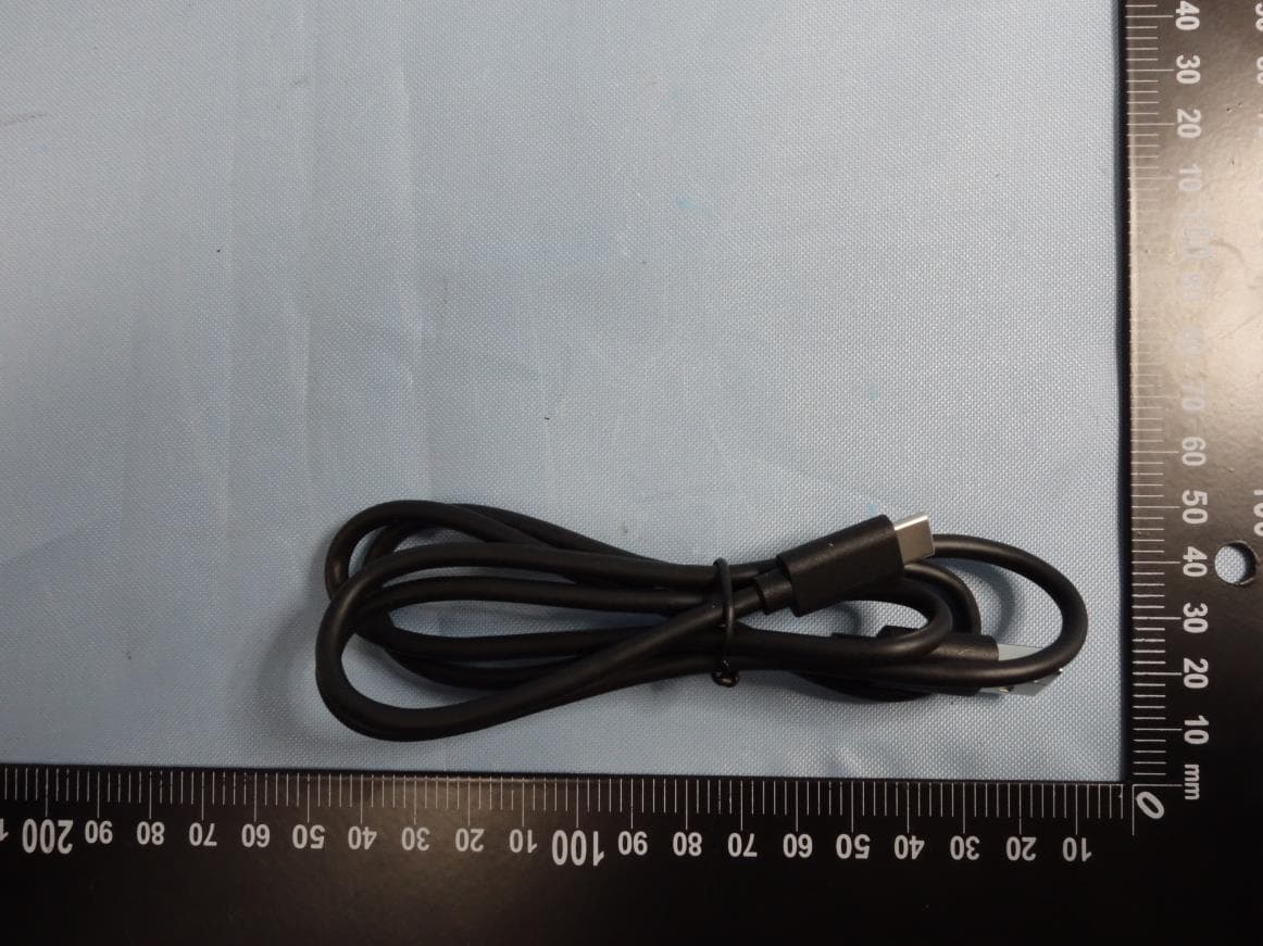
Click to zoom
Application Details
- Equipment Class
- DTS - Digital Transmission System
- Date of Grant
- Nov 22, 2020
- Application Purpose
- Original Equipment
- Date of Application
- Oct 25, 2020
- Equipment Note
- Receiver for CGM
- Frequency Range
- 2402.00000000 - 2480.00000000
- Company
- Bionime Corporation
- Country
- Taiwan
Documents & Files
Document Text
Text extracted from the exhibit documents filed with the FCC. Open a document above to read the original.
Users Manual
101-3HM312-XXXEN User Manual Rev. Date: 2020-06 Continuous Glucose Monitoring System BIONIME CORPORATION No. 100, Sec. 2, Daqing St., South Dist., Taichung City 40242, Taiwan Tel: +886 4 2369 2388 Fax: +886 4 2261 7586 http://www.bionime.com E-mail: [email protected] Use with a receiver BIONIME GmbH Tramstrasse 16 9442 Berneck Switzerland E-mail: [email protected] 0197 1 2 READ THIS FIRST : It is important to read the entire contents of this manual before using the RIGHTEST Continuous Glucose Monitoring System. The instructions, warnings, precautions, safety information as well as tips contained within this manual are intended to help ensure proper use and optimal results. It is important that you read this entire manual before using the system for the first time. 3 CONTENTS I. INDICATIONS FOR USE & STATEMENT AND ADVISORY INDICATIONS FOR USE STATEMENT AND ADVISORY II. SAFETY INFORMATION III. SYMBOL DEFINITIONS IV. GETTING TO KNOW YOUR RIGHTEST CGMS WHAT IS INCLUDED PERFORMANCE FEATURES SAFETY FEATURES THE RIGHTEST CGMS COMPONENTS ACCESSORIES V. BEFORE GETTING STARTED CHARGING BASICS CHARGING THE Receiver (HR310) BATTERY LIFE INDICATOR ON THE Receiver (HR310) CHARGING THE TRANSMITTER 6 6 6 7 16 18 18 20 21 22 23 24 24 25 28 29 4 COTENTS VI. SET UP YOUR RIGHTEST CGMS PAIRING THE SENSOR AND TRANSMITTER USING NFC APPLY YOUR SENSOR ATTACH YOUR TRANSMITTER START SENSOR WITH THE Receiver (HR310) VII. ENDING A MONITORING SESSION END THE MONITORING SESSION SENSOR AND TRANSMITTER REMOVAL VIII.UNDERSTAND YOUR GLUCOSE READINGS HOME SCREEN INDICATOR AND DISPLAYS OVERVIEW GLUCOSE INFORMATION GLUCOSE TREND ARROW AND ARROW COLOR TREND GRAPH ADD NOTES ACCESS YOUR NOTES INFORMATION HIGH/LOW READING IX. REVIEW YOUR GLUCOSE HISTORY 34 34 44 48 52 62 62 64 68 68 70 72 74 76 78 80 82 X. CALIBRATION (OPTIONAL) CALIBRATE XI. TREATMENT DECISIONS WHEN NOT TO USE SENSOR READINGS WHEN MAKING TREATMENT DECISIONS TREND ARROWS AND TREATMENT DECISIONS XII. RIGHTEST CONTINUOUS GLUCOSE MONITORING SYSTEM SPECIFICATIONS SENSOR INSERTER SPECIFICATIONS TRANSMITTER SPECIFICATIONS Receiver (HR310) SPECIFICATIONS TRANSMITTER CHARGER SPECIFICATIONS XIII.CERTIFICATE STATEMENT RF STATEMENT FCC STATEMENT NCC STATEMENT XIV.APPENDIX: ALARM/ALERTS RECEIVER (HR310): GLUCOSE AND SIGNAL LOSS ALERTS RECEIVER (HR310): SYSTEM ALERTS AND NOTIFICATIONS (WITH NO EDITABLE SETTINGS) XV.APPENDIX: CUSTOMER INFORMATION CUSTOMER SERVICE WARRANTY 5 CONTENTS 84 85 88 90 92 96 96 98 100 102 104 104 104 106 108 108 108 126 126 126 6 Indications for Use & Statement and Advisory I. INDICATIONS FOR USE & STATEMENT AND ADVISORY INDICATIONS FOR USE The RIGHTEST Continuous Glucose Monitoring System (the RIGHTEST CGMs) is indicated for detecting glycaemia trends and for the management of diabetes in persons age 4 and older. For the younger user, the personal representative of a minor shall supervise their use with the RIGHTEST CGMs. It's an applied part and it is designed to replace blood glucose testing for diabetes treatment decisions. Interpretation of the RIGHTEST CGMs results shall be based on the glucose trends and several sequential readings over time. It also aids detecting episodes of hyperglycemia and hypoglycemia, facilitating both acute and long-term therapy adjustments. The RIGHTEST CGMs is also intended to autonomously interface with digitally connected devices. The RIGHTEST CGMs can be used alone or in conjunction with these digitally connected devices for the purpose of managing diabetes. STATEMENT AND ADVISORY This manual is designed to instruct all personnel responsible for the proper use and care of the RIGHTEST CGMs. All users are urged to carefully read this manual before using the system. 7 Safety Information II. SAFETY INFORMATION The following is a summary of safety information which must be observed before using the RIGHTEST Continuous Glucose Monitoring System (the RIGHTEST CGMs). WARNING indicates potential danger to user. PRECAUTION indicates potential injury to the user or damage to the system. To minimize risks, read the following safety information before using the system. Improper use and maintenance may damage the system resulting in failure or user injury. It is important to understand that the safety information is not exhaustive. It is meant to keep the user safe while using the system. If you are in the serious incidents caused by the RIGHTEST product, please call local emergency service for help. Please feel free to report your incident to us and the local competent authority. WHEN NOT TO USE (CONTRAINDICATIONS) : No MRI/CT/Diathermy: The RIGHTEST CGMs (sensor, transmitter, Receiver (HR310) and/ or other receiving devices) must be removed prior to Magnetic Resonance Imaging (MRI), Computed Tomography (CT), or high frequency electrical heat (diathermy) treatment. 8 Safety Information WARNINGS : Read This Manual First. Failure to operate the system according to the guidelines and safeguards specified in this manual could result in a hazardous condition. DO NOT Ignore Low/High Blood Glucose Symptoms. If your glucose readings do not match what you are feeling, use your blood glucose meter; or, if needed, consult your healthcare practitioner. Use a Blood Glucose (BG) Meter To Make Treatment Decisions Under The Following Conditions: • During the first 2-hour warmup period when you start a new sensor. You won’t get any sensor readings, alarm/alerts until your system begins to transmit data. • If you suspect that your sensor readings may be inaccurate for any reason. • If your sensor readings do not match what you are feeling. • If you are experiencing symptoms that may be due to low or high blood glucose. • If your sensor readings do not include your current glucose concentration or a glucose trend arrow. • If you wish to confirm hypoglycemia or impending hypoglycemia as reported by the sensor. • If you are experiencing rapid glucose changes (more than 2 mg/dL per minute), the sensor readings displayed may be less accurate and not a…
Text truncated - open the document above for the full version.
External Photos
Appendix P Photo Documentation Page 1 of 15 50349155 001, 50349158 001 Product: Receiver for CGM Type Identification: HR310 Appendix P Photo Documentation Page 2 of 15 50349155 001, 50349158 001 Product: Receiver for CGM Type Identification: HR310 Appendix P Photo Documentation Page 3 of 15 50349155 001, 50349158 001 Product: Receiver for CGM Type Identification: HR310 Appendix P Photo Documentation Page 4 of 15 50349155 001, 50349158 001 Product: Receiver for CGM Type Identification: HR310 Appendix P Photo Documentation Page 5 of 15 50349155 001, 50349158 001 Product: Receiver for CGM Type Identification: HR310 Appendix P Photo Documentation Page 6 of 15 50349155 001, 50349158 001 Product: Receiver for CGM Type Identification: HR310
ID Label/Location Info
Label Receiver for CGM Brand: BIONIME Model: HR310 The back cover of this product will be sealed down for protection and to prevent opening by customer when selling on the market.
Internal Photos
Appendix P Photo Documentation Page 7 of 15 50349155 001, 50349158 001 Product: Receiver for CGM Type Identification: HR310 Appendix P Photo Documentation Page 8 of 15 50349155 001, 50349158 001 Product: Receiver for CGM Type Identification: HR310 Appendix P Photo Documentation Page 9 of 15 50349155 001, 50349158 001 Product: Receiver for CGM Type Identification: HR310 Appendix P Photo Documentation Page 10 of 15 50349155 001, 50349158 001 Product: Receiver for CGM Type Identification: HR310 Appendix P Photo Documentation Page 11 of 15 50349155 001, 50349158 001 Product: Receiver for CGM Type Identification: HR310 Appendix P Photo Documentation Page 12 of 15 50349155 001, 50349158 001 Product: Receiver for CGM Type Identification: HR310 Bluetooth Antenna No RF function use Appendix P Photo Documentation Page 13 of 15 50349155 001, 50349158 001 Product: Receiver for CGM Type Identification: HR310 NFC Antenna Appendix P Photo Documentation Page 14 of 15 50349155 001, 50349158 001 Product: Receiver for CGM Type Identification: HR310 Appendix P Photo Documentation Page 15 of 15 50349155 001, 50349158 001 Product: Receiver for CGM Type Identification: HR310
RF Exposure Info
Produkte Products Prü fbericht - Nr.: Test Report No. 50349155 001 Seite 30 von 35 Page 30 of 35 6. Safety Human exposure 6.1 Radio Frequency Exposure Compliance 6.1.1 Electromagnetic Fields RESULT: Passed Test standard : FCC KDB Publication 447498 D01 v06 47CFR 1.1310 47CFR 2.1091 FCC: Therefore the maximum output power of the transmitter is 0.605mW < 10mW(Distance: 5 mm), hence the EUT is excluded from SAR evaluation according to FCC KDB publication 447498 D01: Mobile Portable RF Exposure. ---End---
Test Report
Test Report No.50349155 001 Appendix D: Radiated and Mains Spurious Emission Data (File: 50349155 001Appendix D) Contents Spurious Emissions, Bandedge....................................................................................................................... 2 Spurious Emissions, TX Mode, 9kHz-30MHz ............................................................................................. 14 Spurious Emissions, TX Mode, 30MHz-1GHz ............................................................................................ 16 Spurious Emissions, TX Mode, 1GHz-26.5GHz.......................................................................................... 18 Spurious Emissions, AC Mains .................................................................................................................... 24 2 Spurious Emissions, Bandedge 3 4 5 6 7 8 9 10 11 12 13 14 Spurious Emissions, TX Mode, 9kHz-30MHz 15 16 Spurious Emissions, TX Mode, 30MHz-1GHz 17 18 Spurious Emissions, TX Mode, 1GHz-26.5GHz 19 20 21 22 23 24 Spurious Emissions, AC Mains 25
Test Report
Prü fbericht - Produkte Test Report - Products Prü fbericht-Nr.: Test report no.: 50349155 001 Auftrags-Nr.: Order no.: 238133847 Seite 1 von 36 Page 1 of 36 Kunden-Referenz-Nr.: Client reference no.: N/A Auftragsdatum: Order date: 03-Feb-2020 Auftraggeber: Client: BIONIME CORPORATION No. 100, Sec. 2, Daqing St., South Dist., Taichung City 40242 Taiwan Prü fgegenstand: Test item: Receiver for CGM Bezeichnung / Typ-Nr.: Identification / Type no.: HR310 Auftrags-Inhalt: Order content: FCC Part 15C Test report (BLE) Prü fgrundlage: Test specification: FCC 47CFR Part 15: Subpart C Section 15.247 Wareneingangsdatum: Date of sample receipt: 19-Feb-2020 Prü fmuster-Nr.: Test sample no: A001062566-002 Prü fzeitraum: Testing period: 19-Feb-2020 – 17-Mar-2020 Ort der Prü fung: Place of testing: EMC/RF Laboratory Taipei Prü flaboratorium: Testing laboratory: TUV Rheinland Taiwan Ltd. Prü fergebnis*: Test result*: Pass ü berprü ft von: reviewed by: genehmigt von authorized by: Datum: 20-Mar-2020 Date: Datum: 20-Mar-2020 Date: Stellung / Position: Mars Y.J. Lin/Project Engineer Stellung / Position: Brenda S. H. Chen/ Project Manager Sonstiges / Other: Zustand des Prü fgegenstandes bei Anlieferung: Condition of the test item at delivery: Prüfmuster vollständig und unbeschädigt Test item complete and undamaged * Legende: 1 = sehr gut 2 = gut 3 = befriedigend 4 = ausreichend 5 = mangelhaft P(ass) = entspricht o.g. Prüfgrundlage(n) F(ail) = entspricht nicht o.g. Prüfgrundlage(n) N/A = nicht anwendbar N/T = nicht getestet * Legend: 1 = very good 2 = good 3 = satisfactory 4 = sufficient 5 = poor P(ass) = passed a.m. test specification(s) F(ail) = failed a.m. test specification(s) N/A = not applicable N/T = not tested Dieser Prü fbericht bezieht sich nur auf das o.g. Prü fmuster und darf ohne Genehmigung der Prü fstelle nicht auszugsweise vervielfältigt werden. Dieser Bericht berechtigt nicht zur Verwendung eines Prü fzeichens. This test report only relates to the a. m. test sample. Without permission of the test center this test report is not permitted to be duplicated in extracts. This test report does not entitle to carry any test mark. TUV Rheinland Taiwan Ltd. 11F., No. 758, Sec. 4, Bade Rd., Taipei 105, Taiwan, R.O.C. Produkte Products Prü fbericht - Nr.: Test Report No. 50349155 001 Seite 2 von 36 Page 2 of 36 TEST SUMMARY 5.1.1 ANTENNA REQUIREMENT RESULT: Passed 5.1.2 PEAK OUTPUT POWER RESULT: Passed 5.1.3 6DB BANDWIDTH AND 99% BANDWIDTH RESULT: Passed 5.1.4 POWER DENSITY RESULT: Passed 5.1.5 CONDUCTED SPURIOUS EMISSIONS AND FREQUENCY BAND EDGE MEASURED IN 100KHZ BANDWIDTH RESULT: Passed 5.1.6 SPURIOUS EMISSION RESULT: Passed 5.2.1 MAINS CONDUCTED EMISSIONS RESULT: Passed 6.1.1 ELECTROMAGNETIC FIELDS RESULT: Passed Produkte Products Prü fbericht - Nr.: Test Report No. 50349155 001 Seite 3 von 36 Page 3 of 36 Contents 1. GENERAL REMARKS ............................................................................................... 5 1.1 COMPLEMENTARY MATERIALS ................................................................................. 5 1.2 DECISION RULE OF CONFORMITY.............................................................................. 5 2. TEST SITES ............................................................................................................ 6 2.1 TEST LABORATORY ................................................................................................ 6 2.2 TEST FACILITY ........................................................................................................ 6 2.3 LIST OF TEST AND MEASUREMENT INSTRUMENTS ...................................................... 7 2.4 TRACEABILITY ........................................................................................................ 8 2.5 CALIBRATION ......................................................................................................... 8 2.6 MEASUREMENT UNCERTAINTY ................................................................................. 8 3. GENERAL PRODUCT INFORMATION ........................................................................... 9 3.1 PRODUCT FUNCTION AND INTENDED USE ................................................................. 9 3.2 SYSTEM DETAILS AND RATINGS ............................................................................... 9 3.3 INDEPENDENT OPERATION MODES ......................................................................... 10 3.4 NOISE GENERATING AND NOISE SUPPRESSING PARTS ............................................ 10 3.5 SUBMITTED DOCUMENTS ....................................................................................... 10 4. TEST SET-UP AND OPERATION MODES ................................................................... 11 4.1 PRINCIPLE OF CONFIGURATION SELECTION ............................................................ 11 4.2 TEST OPERATION AND TEST SOFTWARE................................................................. 11 4.3 SPECIAL ACCESSORIES AND AUXILIARY EQUIPMENT ............................................... 12 4.4 COUNTERMEASURES TO ACHIEVE EMC COMPLIANCE .............................................. 12 4.5 TEST SETUP DIAGRAM .......................................................................................... 13 5. TEST RESULTS ..................................................................................................... 15 5.1 TRANSMITTER REQUIREMENT & TEST SUITES ......................................................... 15 5.1.1 Antenna Requirement ................................................................................................................ 15 5.1.2 Peak output power ..................................................................................................................... 16 5.1.3 6dB Bandwidth and 99% Bandwidth .......................................................................................... 17 5.1.4 Power Density ...............................…
Text truncated - open the document above for the full version.
Test Setup Photos
Produkte Products Prü fbericht - Nr.: Test Report No. 50349155 001 Seite 31 von 35 Page 31 of 35 7. Photographs of the Test Set-Up Photograph 1: Set-up for Spurious Emissions (Front View 1) Photograph 2: Set-up for Spurious Emissions (Front View 2) Produkte Products Prü fbericht - Nr.: Test Report No. 50349155 001 Seite 32 von 35 Page 32 of 35 Photograph 3: Set-up for Spurious Emissions (Back View 1) Photograph 4: Set-up for Spurious Emissions (Back View 2) Produkte Products Prü fbericht - Nr.: Test Report No. 50349155 001 Seite 33 von 35 Page 33 of 35 Photograph 5: Set-up for Spurious Emissions (Back View 3) Photograph 6: Set-up for Spurious Emissions (Back View 4) Produkte Products Prü fbericht - Nr.: Test Report No. 50349155 001 Seite 34 von 35 Page 34 of 35 Photograph 7: Set-up for Mains Conducted testing (Front View) Photograph 8: Set-up for Mains Conducted testing (Back View)
Contact Information
Applicant
Jen Huang(QSS Assistant Manager)
Test Firm
TUV Rheinland Taiwan Ltd. Taipei Testing Lab.Kenji Lin
Technical Specifications
| # | Rule Parts | Frequency Range | Power Output |
|---|---|---|---|
| 1 | 15C | 2.40 GHz - 2.48 GHz | 630.00 µW |
Other Applications from Bionime Corporation

ADU-MAXTEL
Sep 27, 2022Blood Glucose Monitoring System
Equipment Class
PCB - PCS Licensed Transmitter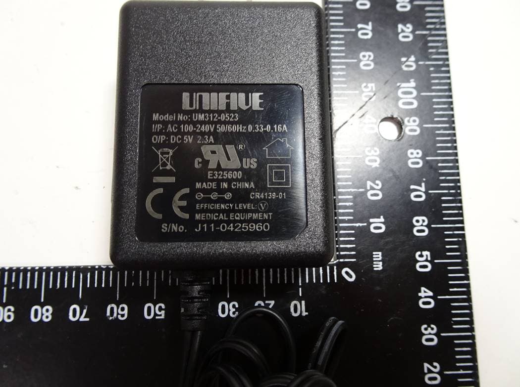
ADU-GM700PRO2
Jul 12, 2021Blood Glucose Meter
Equipment Class
DTS - Digital Transmission System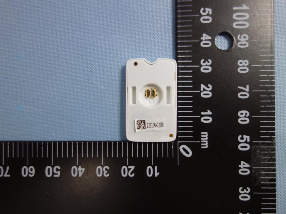
ADU-HM312
Nov 09, 2020RIGHTEST Continuous Glucose Monitoring System (CGMS)
Equipment Class
DTS - Digital Transmission System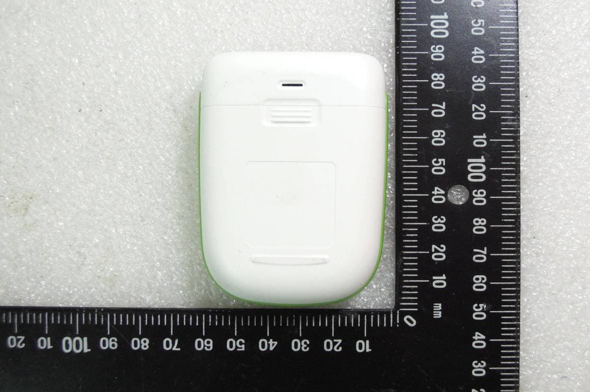
ADU-GM232C
Sep 22, 2015Blood Glucose Meter
Equipment Class
DTS - Digital Transmission System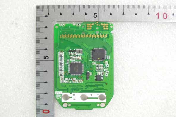
ADU-GM232
Oct 16, 2014Blood Glucose Meter
Equipment Class
DTS - Digital Transmission System