AIERIT50-477DMRUHF DMR Digital / Analog 2-Way Desktop Radio
Ritron Inc
Click to zoom
Application Details
- Equipment Class
- TNB - Licensed Non-Broadcast Station Transmitter
- Date of Grant
- Feb 01, 2021
- Application Purpose
- Original Equipment
- Date of Application
- Feb 01, 2021
- Equipment Note
- UHF DMR Digital / Analog 2-Way Desktop Radio
- Frequency Range
- 450.00000000 - 470.00000000
- Company
- Ritron Inc
- Country
- United States
Documents & Files
Document Text
Text extracted from the exhibit documents filed with the FCC. Open a document above to read the original.
Users Manual
Have questions? Call 800-USA-1-USA (800-872-1872) or visit our website at www.ritron.com Professional Two-Way DMR/Analog Base Radio RBS-Series Base Radio User Manual DMR Digital, Conventional Analog Narrow Band Capable 20 DMR or Analog Channels 2.5 Watt Transmit Power 1 Watt Audio Output 800-USA-1-USA (800-872-1872) www.ritron.com Contents Page INTRODUCTION Default Frequencies & Settings .............................. 1 Optional Replacement Accessories ........................ 1 Basic Features ....................................................... 2 Items Included with the Base Radio ........................ 2 Exposure to Radio Frequency Energy .................... 3 Observe Caution in the Following Environments ..... 3 RADIO OPERATION - GENERAL Radio Controls and Connectors .............................. 4 On-Off Volume Adjust............................................. 5 Channel Selection .................................................. 5 P2 Button ............................................................... 6 RADIO OPERATION – ANALOG CHANNELS Receive – Analog Channels ................................... 8 Transmit – Analog Channels .................................. 8 QC and DQC Tone Codes – Analog Channels ....... 8 Paging Decode Operation – Analog Channels ........ 9 P1 Operation – Analog Channels............................ 9 Contents Page RADIO OPERATION – DMR CHANNELS DMR Channel Overview ........................................10 Receive – DMR Channels .....................................10 Transmit – DMR Channels ....................................11 P1 Button – DMR Channels ..................................11 SPECIFICATIONS General.................................................................12 Receiver ...............................................................12 Transmitter ...........................................................13 RPS-1B Power Supply ..........................................13 General Features ..................................................13 Channel Features .................................................14 Analog Paging Decode .........................................14 FCC AND IC LICENSE REQUIRED FCC Licensing ......................................................15 How to Obtain and FCC License ...........................15 Industry Canada Regulations ................................15 Safety Standards ..................................................15 Service .................................................................15 RITRON WARRANTY INFORMATION ...............................16 RBS-SERIES DMR/ANALOG BASE RADIO USER MANUAL INTRODUCTION Have questions? Call 800-USA-1-USA (800-872-1872) or visit our website at www.ritron.com 1 Dear Valued Ritron Customer, Thank you for your purchase of the RBS-Series DMR/Analog base radio. Each radio comes pre-programmed with the 4 factory default channel frequencies listed below. The frequencies can be changed via the PC programming software and cable. If your company currently has an FCC license on frequencies different from the default frequencies, the radio can be PC programmed to custom frequencies using optional Ritron RBS-DMR-PCPS PC programming software, other settings can also be configured. Please contact your Ritron Reseller for information on “custom” radio programming services. Please be advised that operation on the factory default frequencies require that you obtain an FCC Operator License BEFORE USE. DEFAULT FREQUENCIES AND SETTINGS RBS-477DMR Default Frequency Settings – Operating Band 440-470MHz Freq. Technology Color Code/ Channel Code Frequency Type Tone Freq. TX Power Ch1 FC #5 467.850 MHz DMR Digital 1 Color Code 2.5 Watts Ch2 FC #5 467.850 MHz Analog 77 Hz 2.5 Watts Ch3 FC #3 464.550 MHz DMR Digital 1 Color Code 2.5 Watts Ch4 FC #3 464.550 MHz Analog 77 Hz 2.5 Watts FC# = Frequency Code Analog = Narrow Band (12.5 KHz) OPTIONAL REPLACEMENT ACCESSORIES TO ORDER CALL 800-USA-I-USA AFB-1545 ... Molded Flex, Dual-band Replacement Antenna RAM-I545 .... Magnet-mounted, Dual-band Antenna w / BNC RPS-IB ........ Replacement 110 VAC Power Supply CCL-M ........ 12 VDC, Cigarette Lighter Adaptor JBSK-I2 ...... 12 VDC, Adaptor Kit REP-2 ......... Low Profile Earphone RHD-IX ....... Single Ear Headset RHD-4X ...... Dual Ear Headset RHD-6X ...... Lightweight Behind-the-head Earset w / In-line PTT RHD-8X ...... Lightweight Earbud w / mic and In-line PTT RSM-3XA .... Remote Speaker Microphone RM-7 ........... Hand Microphone & Hang-up Bracket RSP-5 ......... External Speaker w / 5 Watt Audio Capability JBS-MMK ... Mobile Mounting Kit (Does not include screws to mount bracket to wall or vehicle) Call RITRON for a complete listing. JBSK-12 RHD-6X 12-Volt Adapter Kit Behind the Ear Headset RHD-8X Single Earbud Ram-1545 Magnet-mounted Dual-band Antenna RSP-5 RM-7 5-Watt External Speaker Hand Microphone RBS-SERIES DMR/ANALOG BASE RADIO USER MANUAL INTRODUCTION Have questions? Call 800-USA-1-USA (800-872-1872) or visit our website at www.ritron.com 2 BASIC FEATURES This manual covers Ritron RBS-Series DMR/Analog base radio. A rugged, programmable two-way desktop base radio designed to operate in a professional FM communications band. Each radio is equipped with these features: • Analog, DMR and Mixed Mode Operation. The RBS-Series DMR/Analog base radio can operate in Analog, DMR and Mixed Mode technology within the 450- 470MHz frequency band. • Push-button Operating Controls. The Push-To- Talk (PTT), Channel, On / Volume Up, Volume Down / Off; and the special feature P1 and P2 button controls are conveniently located on the face of the radio. • 16 Character LCD Display. A backlit, 2-line x 8-character, LCD display will show the channel, volume, and many current operating conditions. • 20-Channel Capability. Up to 20 channels can be programmed to contain a unique set of operating frequencies and options. Each channel can be programmed for Analog, DMR or Mixed Mode operation; a…
Text truncated - open the document above for the full version.
Attestation Statements
Ritron, Inc. 505 W . Carmel Drive Carmel, IN 46032-7564 P.O. Box 1998 Carmel, IN 46082-1998 Ph: 317-846-1201 Fax: 317-846-4978 Email: [email protected] Web Site: www.ritron.com December 29, 2020 Federal Communications Commission Authorization and Evaluation Division, 7435 Oakland Mills Road Columbia, MD 21046 USA SUBJECT: Applications for Certification for FCC: AIERIT50-477DMR Gentlemen: The equipment meets the requirements of the FCC Rules, Part 90.203(e) and (g), as applicable. Programming of this product’s transmit frequencies can be performed ONLY by the manufacturer or by service or maintenance personal. The operator cannot program transmit frequencies using the equipment’s external operation controls. Sincerely, Sam L. Dulaney
Cover Letter(s)
Page 1 RBS-477DMR_ConfidReq.pdf Ritron, Incorporated 505 W. Carmel Drive · Carmel, IN 46032 P. O. Box 1998 · Carmel, IN 46082 Ph: 317-846-1201 Email: [email protected] Web Site: www.ritron.com November 20, 2020 Ritron Inc. 505 West Carmel Dr. Carmel, IN 46032 Federal Communications Commission Authorization and Evaluation Division Confidentiality Request regarding application for certification of FCC ID: AIERIT50-477DMR Pursuant to Sections 0.457 and 0.459 of the Commission’s Rules, we hereby request long term confidential treatment of information accompanying this application as outlined below: Exhibit Type File Name Block Diagram Schematic – Main Board Schematic – DMR Board Operational Description Semiconductor List Tune-up Procedure RBS-477DMR_BlkDia.pdf RBS-477DMR_G1751361C_SCH.pdf RBS-DMR_G1751351B_SCH.pdf RBS-477DMR_OpDes.pdf RBS-477DMR_PartsLst.pdf RBS-477DMR_TunPro.pdf The above materials contain trade secrets and proprietary information not customarily released to the public. The public disclosure of these materials may be harmful to the applicant and provide unjustified benefits to its competitors. The applicant understands that pursuant to Section 0.457 of the Rules, disclosure of this application and all accompanying documentation will not be made before the date of the Grant for this application. Sincerely, Sam L. Dulaney Chief Engineer Ritron, Inc. Email: [email protected]
Cover Letter(s)
Page 1 RBS-477DMR_FreqJust.pdf Ritron, Incorporated 505 W. Carmel Drive · Carmel, IN 46032 P. O. Box 1998 · Carmel, IN 46082 Ph: 317-846-1201 Email: [email protected] Web Site: www.ritron.com November 20, 2020 Office of Engineering and Technology Laboratory Division Equipment Authorization Branch FCC Laboratory7435 Oakland Mills Rd. Columbia, MD 21046 Re: Extended Frequency Justification on FCC ID: AIERIT50-477DMR To whom it may concern: The RBS-477DMR two-way desktop radio is designed to operate in the frequency band 450-470 MHz. To aid equipment authorization in other countries within ITU regions 1, 2 or 3 which accept the United States FCC Grant for certification, Ritron is requesting that the FCC lists the frequencies 450-470 MHz under FCC Rule Parts 90 on the FCC Grant. This product is also intended for Federal end users. For the FCC’s Rule Part 90 applications, this radio is used in systems by OEM systems integrators as indicated in the table below. Equipment programming is the responsibility of Authorized Service Personnel. Also, the radio complies with 47 CFR Part 90.203(e) in that the operator cannot directly program the transmit frequencies using the normally accessible external controls. Per the FCC’s KDB634817 guidance, “as an alternative to listing the exact frequencies, we acknowledge that it’s a violation of the FCC Rules if this device operates on unauthorized frequencies.” Frequency Range (MHz) Part 90 Federal Customers/ Not Part 90 Grant Notes Emission Designators Part 90 450.0000 – 454.0000 x EF 11K0F3E, 7K60FXD,7K60FXE, 7K60FXW 454.0000 – 456.0000 x EF 11K0F3E, 7K60FXD,7K60FXE, 7K60FXW 456.0000 – 462.5375 x EF 11K0F3E, 7K60FXD,7K60FXE, 7K60FXW 462.5375 – 462.7375 x EF 11K0F3E, 7K60FXD,7K60FXE, 7K60FXW 462.7375 – 467.5375 x EF 11K0F3E, 7K60FXD,7K60FXE, 7K60FXW 467.5375 – 467.7375 x EF 11K0F3E, 7K60FXD,7K60FXE, 7K60FXW 467.7375 – 470.0000 x EF 11K0F3E, 7K60FXD,7K60FXE, 7K60FXW Sincerely, Sam L. Dulaney Chief Engineer Ritron, Inc. Email: [email protected]
Cover Letter(s)
Ritron, Inc. 505 W. Carmel Drive • Carmel, IN 46032-7564 P.O. Box 1998 • Carmel, IN 46082-1998 Ph: 317-846-1201 Fax: 317-846-4978 Email: [email protected] Web Site: www.ritron.com November 20, 2020 Timco Engineering, Inc. 849 N.W. State Road 45 P.O. Box 370 Newberry, FL 32669 SUBJECT: App lications for Certification for FCC ID: AIERIT50-477DMR To Whom It May Concern: We, the undersigned, hereby authorize Sharon Hoffman at Timco Engineering, Inc. on our behalf, to apply to the Federal Communications Commission for certification on our equipment referenced above. Any and all acts carried out by Timco Engineering, I nc. on our behalf shall have the same effect as acts of our own. This is to advise that we are in full compliance with the Anti- Drug Abuse Act. We, the applicant, are not subject to a denial of federal benefits pursuant to Section 5301 of the Anti-Drug Act of 1988, 21 USC853a, and no party to the application is subject to a denial of federal benefits pursuant to that section. Regards, S am L. Dulaney
External Photos
Page 1 RBS-477DMR_ExtPho.pdf TYPE OF EXHIBIT: EXTERNAL PHOTOGRAPHS FCC PART: 2.1033(c)(12) IC PART: RSP-100, Section 7.2 (d) MANUFACTURER: RITRON, INC. MODELS: RBS-477DMR TYPE OF UNIT: UHF DMR Digital / Analog 2-Way Desktop Radio FCC ID: AIERIT50-477DMR IC ID: 1084A-RIT50477DMR DATE: November 20, 2020 Included in this exhibit are photographs of the RITRON Model RBS-477DMR case assembly. Additional photographs of the radio printed circuit board construction and installation are included with this certification request as separate exhibits. SIGNED: Michael A. Pickard - Project Engineer Page 2 RBS-477DMR_ExtPho.pdf EXHIBIT: RBS-477DMR front view showing controls and display FCC ID: AIERIT50-477DMR IC ID: 1084A-RIT50477DMR Page 3 RBS-477DMR_ExtPho.pdf EXHIBIT: RBS-477DMR back view showing location of FCC ID label FCC ID: AIERIT50-477DMR IC ID: 1084A-RIT50477DMR Page 4 RBS-477DMR_ExtPho.pdf EXHIBIT: RBS-477DMR bottom view showing audio and programming jacks FCC ID: AIERIT50-477DMR IC ID: 1084A-RIT50477DMR EXHIBIT: RBS-477DMR top view showing controls DC power and antenna connectors FCC ID: AIERIT50-477DMR IC ID: 1084A-RIT50477DMR EXHIBIT: RBS-477DMR right side view FCC ID: AIERIT50-477DMR IC ID: 1084A-RIT50477DMR EXHIBIT: RBS-477DMR left side view FCC ID: AIERIT50-477DMR IC ID: 1084A-RIT50477DMR
ID Label/Location Info
Page 1 RBS-477DMR_LabelLoc.pdf TYPE OF EXHIBIT: FCC/IC ID LABEL LOCATION FCC PART: 2.1033 IC PART: RSS-Gen, Section 5.2 MANUFACTURER: RITRON, INC. MODELS: RBS-477DMR TYPE OF UNIT: UHF DMR Digital / Analog 2-Way Desktop Radio FCC ID: AIERIT50-477DMR IC ID: 1084A-RIT50477DMR DATE: November 20, 2020 Photograph indicates the location of the FCC/IC label on the case back. A label drawing is included with this certification request as a separate exhibit. SIGNED: Michael A. Pickard - Project Engineer
ID Label/Location Info
Page 1 RBS-477DMR_LabelSmpl.pdf TYPE OF EXHIBIT: FCC/IC ID LABEL SAMPLE FCC PART: 2.1033 IC PART: RSS-Gen, Section 5.2 MANUFACTURER: RITRON, INC. MODELS: RBS-477DMR TYPE OF UNIT: UHF DMR Digital / Analog 2-Way Desktop Radio FCC ID: AIERIT50-477DMR IC ID: 1084A-RIT50477DMR DATE: November 20, 2020 Ritron drawing 14200215A specifies the FCC label for model RBS-477DMR. Photographs to indicate the position of the label on the case are included with this certification request as a separate exhibit. Each serial number is recorded, along with the date of manufacture, and is kept on file at RITRON, Inc. The size of the serial label is 2.00” by 1.25”. SIGNED: Michael A. Pickard - Project Engineer Page 2 RBS-477DMR_LabelSmpl.pdf 1 2 3 4 5 RITRON, INC. 505 West Carmel Drive Carmel, IN 46032 DRAWN BY CHK’D TRACED SCALE DATE APP’D MATERIAL DRAWING NO. REVISIONS NO. DATE BY TOLERANCES (EXCEPT AS NOTED) DECIMAL ± FRACTIONAL ± ANGULAR ± SERIAL LABEL FCC / IC ID MODEL: RBS-477DMR MAP 2:1 10/12/20 14200215A NOTES: 1. MATERIAL IS Zebra 8000T 2x1.25 Polyester VOID (RITRON PN 14290021) 2. SILVER BACKGROUND LABEL WITH BLACK GRAPHICS. 3. ALL CHARACTERS ARE ARIAL TYPE STYLE, 4 POINT TYPE SIZE. 4. SERIALIZATION IS A 10-DIGIT RITRON NUMBER. 5. MODELS INCLUDED PER THIS DRAWING LISTED AT RIGHT. MODELS: RBS-477DMR 1.25” 2.00” Product satisfies general population requirements for RF exposure. See user manual for operating requirements. SN: A100123456 ATTENTION
Internal Photos
Page 1 RBS-477DMR_IntPho.pdf TYPE OF EXHIBIT: INTERNAL PHOTOGRAPHS FCC PART: 2.1033(c)(12) IC PART: RSP-100, Section 7.2 (d) MANUFACTURER: RITRON, INC. MODELS: RBS-477DMR TYPE OF UNIT: UHF DMR Digital / Analog 2-Way Desktop Radio FCC ID: AIERIT50-477DMR IC ID: 1084A-RIT50477DMR DATE: November 20, 2020 Included in this exhibit are photographs of the RITRON Model RBS-477DMR printed circuit board assemblies and installation. Additional photographs of the radio construction and layout, labels, and chassis assembly are included with this certification request as separate exhibits. SIGNED: Michael A. Pickard - Project Engineer Page 2 RBS-477DMR_IntPho.pdf EXHIBIT: RBS-477DMR main board complete top side PCB assembly with shields removed FCC ID: AIERIT50-477DMR IC ID: 1084A-RIT50477DMR EXHIBIT: RBS-477DMR main board complete top side PCB assembly with shields installed FCC ID: AIERIT50-477DMR IC ID: 1084A-RIT50477DMR Page 3 RBS-477DMR_IntPho.pdf EXHIBIT: RBS-477DMR main board complete bottom side PCB assembly FCC ID: AIERIT50-477DMR IC ID: 1084A-RIT50477DMR EXHIBIT: RBS-477DMR DMR sub-board complete bottom side PCB assembly FCC ID: AIERIT50-477DMR IC ID: 1084A-RIT50477DMR Page 4 RBS-477DMR_IntPho.pdf EXHIBIT: RBS-477DMR DMR sub-board complete top side PCB assembly with shields removed FCC ID: AIERIT50-477DMR IC ID: 1084A-RIT50477DMR EXHIBIT: RBS-477DMR DMR sub-board complete top side PCB assembly with shields installed FCC ID: AIERIT50-477DMR IC ID: 1084A-RIT50477DMR Page 5 RBS-477DMR_IntPho.pdf EXHIBIT: RBS-477DMR PCB assemblies installed in case FCC ID: AIERIT50-477DMR IC ID: 1084A-RIT50477DMR
RF Exposure Info
Page 1 RBS-477DMR_RFExp.pdf TYPE OF EXHIBIT: MPE (Maximum Permissible Exposure) Calculation FCC PART: 2.1091(d)(4) IC PART: MANUFACTURER: RITRON, INC. MODELS: RBS-477DMR TYPE OF UNIT: UHF DMR Digital / Analog 2-Way Desktop Radio FCC ID: AIERIT50-477DMR IC ID: 1084A-RIT50477DMR DATE: November 20, 2020 DETERMINING MPE DISTANCE: Because this product is used as a mobile device, an RF calculation can be done to determine maximum permissible exposure. The RBS-477DMR MPE is calculated at the maximum output power of 2.5W with the following 2 antennas: AFB-1545 (included with radio) -2 dBi gain RAM-1545 (optional magnet-mount antenna) 2 dBi gain The ERP must be converted to EIRP to simulate an isotropic radiator. Typical transmit duty cycles are between 5% and 10%. Over the 30 minute averaging period for General Population/Uncontrolled MPE limits, a 50% maximum duty cycle is reasonable, and will be used in the MPE calculations for this device. Since the unit is categorized as a mobile radio, a 50% duty cycle may be used, therefore EIRP = 1.64 (ERP/2). For the RBS-477DMR w/AFB-1545: EIRP = 1.29 W For the RBS-477DMR w/RAM-1545: EIRP = 3.25 W Power density is related to EIRP: S(W/m 2 ) = EIRP(W)/4πr 2 where r is the distance from the source in meters. Solving for distance as a function of transmitter power and required power density per area we get: _________ r = √(EIRP/4πS) The MPE (maximum permissible exposure) for a device operating in a General Population/Uncontrolled exposure environment is f(MHz)/1500 mW/cm 2 . Converting to W/m 2 , the limit becomes f(MHz)/150 W/m 2 . The MPE limit is substituted for S and EIRP is entered in the above equation. Required antenna separation for AFB-1545 (included with radio) Frequency EIRP Duty Cycle S limit Distance Distance (MHz) (Watts) (%) (W/m 2 ) (cm) (in) 450.000 1.29 50 3.00 18.5 7.3 460.000 1.29 50 3.07 18.3 7.2 470.000 1.29 50 3.13 18.1 7.1 Required antenna separation for RAM-1545 (optional magnet-mount antenna) Frequency EIRP Duty Cycle S limit Distance Distance (MHz) (Watts) (%) (W/m 2 ) (cm) (in) 450.000 3.25 50 3.00 29.4 11.6 460.000 3.25 50 3.07 29.0 11.4 470.000 3.25 50 3.13 28.7 11.3 SIGNED: Michael A. Pickard - Project Engineer Page 2 RBS-477DMR_RFExp.pdf TYPE OF EXHIBIT: MPE (Maximum Permissible Exposure) Calculation FCC PART: 2.1091(d)(4) IC PART: MANUFACTURER: RITRON, INC. MODELS: RBS-477DMR TYPE OF UNIT: UHF DMR Digital / Analog 2-Way Desktop Radio FCC ID: AIERIT50-477DMR IC ID: 1084A-RIT50477DMR DATE: November 20, 2020 RF WARNING STATEMENT: The following statement appears in the User Manual regarding RF safety: EXPOSURE TO RADIO FREQUENCY ENERGY These products generate radio frequency (RF) energy when the PTT button on the front of the unit is depressed. The product has been evaluated for compliance with the maximum permissible exposure limits for RF energy at the maximum power rating of the unit when using antennas available from RITRON. Antennas other than those mentioned below have not been tested for compliance and may or may not meet the exposure limits at the distances given. Higher gain antennas are capable of generating higher fields in the strongest part of their field and would, therefore, require a greater separation from the antenna. AFB-1545 (included with radio) -2 dBi gain RAM-1545 (optional magnet-mount antenna) 2 dBi gain RBS-477DMR: Using the AFB-1545 antenna (included with the product) in a vertical orientation at the 20 cm (7.9 inches) minimum expected separation distance and greater, the maximum RF exposure is well below the General Population/Uncontrolled limits. When using the RAM-1545 (optional magnet-mount antenna with 25’ cable) in a vertical orientation a 29.4 cm separation distance is required. Antennas other than those available from RITRON have not been tested for compliance and may or may not meet the exposure limits at the distances given. Higher gain antennas are capable of generating higher fields in the strongest part of their field and would, therefore, require a greater separation from the antenna. This product is not to be used by the general public in an uncontrolled environment unless compliance with the Uncontrolled/General Population limits for RF exposure can be assured. En utilisant l'antenne AFB-1545 (fournie avec le produit) dans une orientation verticale à la distance de séparation minimale prévue de 20 cm (7.9 pouces) et plus, l'exposition RF maximale est bien inférieure aux limites de la population générale / non contrôlées. Lors de l'utilisation de la RAM-1545 (antenne optionnelle à montage magnétique avec câble de 25 pi) dans une orientation verticale, une distance de séparation de 29.4 cm est requise. Les antennes autres que celles disponibles chez RITRON n'ont pas été testées pour leur conformité et peuvent ou non respecter les limites d'exposition aux distances indiquées. Les antennes à gain plus élevé sont capables de générer des champs plus élevés dans la partie la plus forte de leur champ et nécessiteraient donc une plus grande séparation de l'antenne. Ce produit ne doit pas être utilisé par le grand public dans un environnement non contrôlé, à moins que le respect des limites d'exposition aux RF pour la population non contrôlée / générale ne puisse être assuré. To limit exposure to RF energy to levels below the limit, please observe the following: • Use only the antenna(s) available from RITRON for these models. DO NOT operate the radio without an antenna. • DO NOT transmitter more than 50% of the time. • When transmitting, make certain that the distance limits for the particular model in use are observed. • DO NOT allow children to operate the radio. When used as directed, this series of radios is designed to comply with the FCC and IC RF exposure limits for “Uncontrolled/General Population”. In addition, they are designed to comply with the following Standards and Guidelines: • United States Federal Communications Commission, Code of Federal Regulations; 47 CFR §§ 2 sub-part J. •…
Text truncated - open the document above for the full version.
Test Report
Test Report # TR_4612 -20_FCC_PT90_2 Revision: 2 Issue Date: December 4, 2020 Final Test Date: December 28, 2020 An IIA Company Test Report - FCC PART 90 (TNB) Prepared For: RITRON, INC. Approved for Release By: Signature: Name & Title: Bruno Clavier, General Manager Date of Signature (YYYY-MM-DD): 2020-11 -30 This test report shall not be reproduced except in full without the written and signed permission of Timco Engineering Inc. (IIA). This test report relates only to the items tested as identified and is not valid for any subsequent changes or modifications made to the equipment under test. Timco Engineering, Inc., an IIA Company 849 NW State Road 45, Newberry, Florida 32669 (352) 472-5500 / [email protected] Page 2 of 49 This test report shall not be reproduced except in full without the written and signed permission of Timco Engineering Inc. (IIA). Table of Contents 1. CUSTOMER INFORMATION ........................................................................................................................................................................... 4 1.1 PART 90 TEST RESULT SUMMARY ............................................................................................................................................................................4 2. LOCATION OF TESTING ................................................................................................................................................................................. 5 2.1 TEST LABORATORY .................................................................................................................................................................................................... 5 2.2 TESTING WAS PERFORMED, REVIEWED BY ................................................................................................................................................................ 5 3. TEST SAMPLE(S) (EUT/DUT) ........................................................................................................................................................................... 6 3.1 DESCRIPTION OF THE EUT ........................................................................................................................................................................................ 6 3.2 CONFIGURATION OF EUT ......................................................................................................................................................................................... 7 3.3 TEST SETUP OF EUT .................................................................................................................................................................................................. 7 4. TEST METHODS & APPLICABLE REGULATORY LIMITS ............................................................................................................................ 8 4.1 TEST METHODS/STANDARDS/GUIDANCE: ............................................................................................................................................................... 8 4.2 APPLIED LIMITS AND REGULATORY LIMITS: .............................................................................................................................................................. 8 5. MEASUREMENT UNCERTAINTY .................................................................................................................................................................... 8 6. ENVIRONMENTAL CONDITIONS ................................................................................................................................................................. 8 6.1 TEMPERATURE & HUMIDITY ...................................................................................................................................................................................... 8 7. LIST OF TEST EQUIPMENT AND TEST FACILITY ........................................................................................................................................ 9 7.1 LIST OF TEST EQUIPMENT ......................................................................................................................................................................................... 9 8. TEST RESULTS ................................................................................................................................................................................................. 10 8.1 POWER AT THE FINAL AMPLIFIER ............................................................................................................................................................................. 11 8.2 RF OUTPUT POWER ................................................................................................................................................................................................ 12 8.3 BANDWIDTH & EMISSION ....................................................................................................................................................................................... 13 8.3.1 Bandwidth Plot, 99%, 450 MHz Analog ........................................................................................................................................... 14 8.3.1 Bandwidth Plot, 99%, 460 MHz Analog .......................................................................................................................................... 15 8.3.1 Bandwidth Plot, 99%, 470 MHz Analog ........................................................................................................................................... 16 8.3.2 Bandwidth Plot, 99%, 450 MHz DMR ............................................................................................................................................... 17 8.3.3 Bandwidth Plot, 99%, 460 MHz DMR .................................…
Text truncated - open the document above for the full version.
Test Setup Photos
Ritron, Inc. FCC ID: AIERIT50-477DMR IC: 1084A-RIT50477DMR Test Setup Photographs Conducted Test Setup Radiated, Table Setup Radiated, Below 1 GHz Radiated, Below 1 GHz #2 Frequency Stability
Contact Information
Applicant
Sam L. Dulaney(Chief Engineer)
Test Firm
Timco Engineering, Inc.Bruno Clavier
Technical Specifications
| # | Rule Parts | Frequency Range | Power Output | Emission | Tolerance |
|---|---|---|---|---|---|
| 4 | 9 | 450 MHz - 470 MHz | 2.5 W | 7K60FXW | 128 Hz |
Other Applications from Ritron Inc

AIERIT53-16006
Jan 04, 2023VHF Transceiver
Equipment Class
TNB - Licensed Non-Broadcast Station Transmitter
AIERIT39-26006
Aug 26, 2021VHF Modem Transceiver
Equipment Class
TNB - Licensed Non-Broadcast Station Transmitter
AIERIT51-46530
Jul 25, 2021UHF Transceiver
Equipment Class
TNB - Licensed Non-Broadcast Station Transmitter
AIERIT51-16006
Jan 19, 2021VHF Transceiver
Equipment Class
TNB - Licensed Non-Broadcast Station Transmitter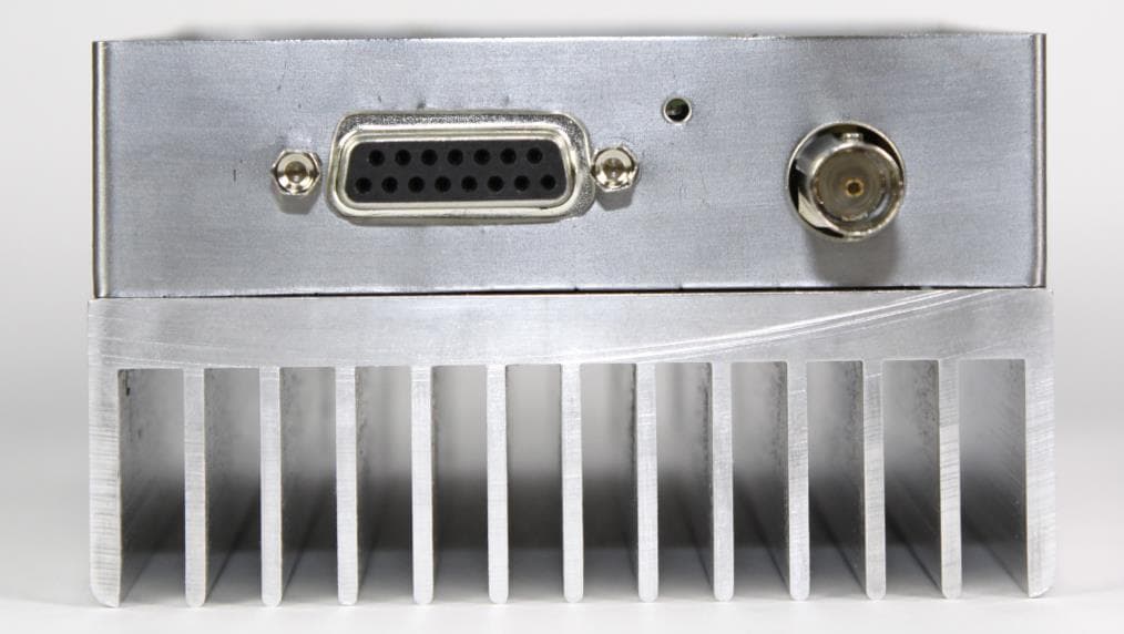
AIERIT34-4650
Dec 10, 2015UHF Transceiver Module
Equipment Class
TNB - Licensed Non-Broadcast Station Transmitter