AIERIT51-46530UHF Transceiver
Ritron Inc
Click to zoom
Application Details
- Equipment Class
- TNB - Licensed Non-Broadcast Station Transmitter
- Date of Grant
- Jul 25, 2021
- Application Purpose
- Original Equipment
- Date of Application
- Jul 25, 2021
- Equipment Note
- UHF Transceiver
- Frequency Range
- 450.00000000 - 470.00000000
- Company
- Ritron Inc
- Country
- United States
Documents & Files
Document Text
Text extracted from the exhibit documents filed with the FCC. Open a document above to read the original.
Users Manual
RITRON, INC. 05-2021 RITRON MODEL: DTXM-465-0BN6I-M PROGRAMMABLE FM TRANSCEIVER MODULE USER MANUAL TABLE OF CONTENTS I DTXM MODULES 1 INTRODUCTION 1.1 GENERAL 1.2 MODEL IDENTIFICATION 1.3 FCC/IC REGULATIONS 2 SPECIFICATIONS 2.1 GENERAL 2.2 TRANSMITTER 2.3 RECEIVER 3 DTXM INPUT/OUTPUT CONNECTOR 4 ACCESSORIES 5 OPERATION 5.1 CHANNEL SELECTION 5.2 POWER SUPPLY VOLTAGE 5.3 CURRENT DRAIN vs SUPPLY VOLTAGE 5.4 DUTY CYCLE/KEY-DOWN LIMITATIONS 5.5 OPERATING MODES 6 PROGRAMMING 6.1 PC PROGRAMMING KIT 6.2 LOADING THE PROGRAMMING SOFTWARE 6.3 COMPUTER SOFTWARE COPYRIGHTS 6.4 USING THE PROGRAMMING SOFTWARE 6.5 PROGRAMMER MENUS II MAINTENANCE 7 IMPORTANT MAINTENANCE INFORMATION 8 HARDWARE OPTIONS 8.1 CONTROLLER/LOADER BOARD OPTIONS 8.2 RF BOARD OPTIONS 1 INTRODUCTION 1.1 GENERAL The RITRON DTXM Plus modules are programmable 2-way radios, which operate either in the VHF or UHF professional FM communications bands as well as a number of other bands in the 220 MHz and 350 MHz region. Each of four channels can be programmed to contain a unique set of operating frequencies. The DTXM Plus module is made up of two PC boards, an RF board and a control/loader board. These two boards are enclosed in a metal case with two connectors on one end; a 50 ohm BNC connector for connection to an antenna and a DB-15 sub-miniature connector for power and control input/output. In addition, the RF board is available as a stand-alone unit for system integrators. 1.2 MODEL IDENTIFICATION The DTXM has a part number in the form of “DTXM-A60-BCDEF” Where: A is the major frequency band designator: 1=VHF (136-174 MHz) 2=217-245 MHz 3=340-400 MHz 4=UHF (400-520 MHz) B is the sub-band designator: G=340-360 and 400-420 A=420-440 B=430-450 0=136-174, 217-245, 360-380, and 450-470 M=380-400 C=470-490 T=490-512 C is the connector designator: B=BNC connector M= MCX connector S=SMA connector D designates the channel bandwidth: S=6.25 kHz N=12.5 kHz W=25 kHz E designates the maximum power level: 3=3 watts 6=6 watts 9=10 watts F designates the regulator option I=Internal regulator (10-16 VDC operation with regulated RF power amplifier) D=No regulator (7.5 VDC operation) L=RF PA is unregulated, but the remainder of the modem is regulated (10-watt versions) Example: A DTXM-465-OBN6I would be a UHF module for operation between 450 and 470 MHz with a BNC RF connector, narrow (12.5 kHz channel spacing) IF bandwidth, 30 watts maximum output power, and an internal regulator to allow operation from 10 to 15 volts. 1.3 FCC/IC REGULATIONS 1.3.1 LICENSING For those frequency bands governed by FCC rules, the FCC requires that the radio owner obtain a station license for his radio before using the equipment to transmit, but does not require an operating license or permit. The station licensee is responsible for proper operation and maintenance of his radio equipment, and for ensuring that transmitter power, frequency and deviation are within the limits specified by the station license. This includes checking the transmitter frequency and deviation periodically using appropriate methods. Note also, that wideband operation (25/30 kHz channel bandwidth) may not be permitted. 1.3.2 PRODUCT CERTIFICATION The DTXM modules are certified by the FCC for operation in the United States and by Industry Canada for operation in Canada on certain frequency bands and sub-bands for transmission of either voice or data signals when aligned according to the alignment procedure for the proper bandwidth and when operated as a complete unit in the metal case. Operation of the RF board as a stand-alone unit or in combination with any other equipment, in any mode outside the alignment procedure, or with the clipper filter electronically disabled will require the filing of a new type acceptance application with the FCC by the user. 1.3.3 SAFETY STANDARDS-RF EXPOSURE RF ENERGY EXPOSURE AWARENESS AND CONTROL INFORMATION, AND OPERATIONAL INSTRUCTIONS FOR FCC OCCUPATIONAL USE REQUIREMENTS: BEFORE USING THIS 2-WAY RADIO, READ THIS IMPORTANT RF ENERGY AWARENESS AND CONTROL INFORMATION AND OPERATIONAL INSTRUCTIONS TO ENSURE COMPLIANCE WITH THE FCC’S AND IC’S RF EXPOSURE GUIDELINES. THIS DEVICE COMPLIES WITH PART 15 OF THE FCC RULES. OPERATION IS SUBJECT TO THE FOLLOWING TWO CONDITIONS: (1) THIS DEVICE MAY NOT CAUSE HARMFUL INTERFERENCE, AND (2) THIS DEVICE MUST ACCEPT ANY INTERFERENCE RECEIVED, INCLUDING INTERFERENCE THAT MAY CAUSE UNDESIRED OPERATION. NOTE: THE GRANTEE IS NOT RESPONSIBLE FOR ANY CHANGES OR MODIFICATIONS NOT EXPRESSLY APPROVED BY THE PARTY RESPONSIBLE FOR COMPLIANCE. SUCH MODIFICATIONS COULD VOID THE USER’S AUTHORITY TO OPERATE THE EQUIPMENT. NOTICE: This radio is intended for use in general population/uncontrolled conditions, where users do not have full knowledge of their exposure and cannot exercise control over their exposure to meet FCC/IC limits. This 2-way radio uses electromagnetic energy in the radio frequency (RF) spectrum to provide communications between two or more users over a distance. It uses radio frequency (RF) energy or radio waves to send and receive calls. RF energy is one form of electromagnetic energy. Other forms include, but are not limited to, electric power, sunlight and x-rays. RF energy, however, should not be confused with these other forms of electromagnetic energy, which when used improperly can cause biological damage. Very high levels of x-rays, for example, can damage tissues and genetic material. Experts in science, engineering, medicine, health and industry work with organizations to develop standards for exposure to RF energy. These standards provide recommended levels of RF exposure for both workers and the general public. These recommended RF exposure levels include substantial margins of protection. All 2-way radios marketed in North America are designed, manufactured and tested to ensure they meet government established RF exposure levels. In addition, manufacturers also recommend specific operating instructions to users of 2…
Text truncated - open the document above for the full version.
Attestation Statements
Ritron, Incorporated 505 W. Carmel Drive · Carmel, IN 46032 P. O. Box 1998 · Carmel, IN 46082 Ph: 317-846-1201 Fax: 317-846-4978 Email: [email protected] Web Site: www.ritron.com Federal Communications Commission Authorization and Evaluation Division, 7435 Oakland Mills Road Columbia, MD 21046 USA 05/12/2021 Re: FCC ID: AIERIT51-46530 Type Acceptance Submission Gentlemen: The equipment meets the requirements of the FCC Rules, Part 90.203(e) and (g), as applicable. Programming of this product’s transmit frequencies can ONLY be performed by the manufacturer or by service or maintenance personal. The operator cannot program transmit frequencies using the equipment’s external operation controls. Sincerely, Sam L. Dulaney Chief Engineer Ritron, Inc.
Cover Letter(s)
Ritron, Incorporated 505 W. Carmel Drive · Carmel, IN 46032 P. O. Box 1998 · Carmel, IN 46082 Ph: 317-846-1201 Fax: 317-846-4978 Email: [email protected] Web Site: www.ritron.com Date: 05/12/2021 Timco Engineering, Inc. 849 N.W. State Road 45 P.O. Box 370 Newberry, FL 32669 SUBJECT: Application(s) for Certification for IC: 1084A-RIT5146530, FCC ID: AIERIT51-46530, Models DTXM-465-0BN30I-M and DTXM-465-0BN30I-NXDN To Whom It May Concern: We, the undersigned, hereby authorize Sharon Hoffman at TIMCO ENGINEERING, INC. on our behalf, to apply for certification on our equipment referenced above. Any and all acts carried out by TIMCO ENGINEERING, INC. on our behalf shall have the same effect as acts of our own. This is to advise that we are in full compliance with the Anti- Drug Abuse Act. We, the applicant, are not subject to a denial of federal benefits pursuant to Section 5301 of the Anti-Drug Act of 1988, 21 USC853a, and no party to the application is subject to a denial of federal benefits pursuant to that section. Regards, Sam L. Dulaney Chief Engineer
Cover Letter(s)
Ritron, Incorporated 505 W. Carmel Drive · Carmel, IN 46032 P. O. Box 1998 · Carmel, IN 46082 Ph: 317-846-1201 Email: [email protected] Web Site: www.ritron.com May 13, 2021 Office of Engineering and Technology Laboratory Division Equipment Authorization Branch FCC Laboratory7435 Oakland Mills Rd. Columbia, MD 21046 Re: Extended Frequency Justification on FCC ID: AIERIT51-46530 To whom it may concern: The DTXM-465-0BN30I-NXDN, 30 watt, OEM radio transceiver was designed to operate in the frequency band 450- 470 MHz. To aid equipment authorization in other countries which accept the United States FCC Grant for certification, Ritron is requesting that the FCC lists the frequencies 450-470 MHz under FCC Rule Parts 90 on the FCC Grant. For the FCC’s Rule Part 90 applications, this radio is used in systems by OEM systems integrators as indicated in the table below. Equipment programming is the responsibility of Authorized Service Personnel. Also, the radio complies with 47 CFR Part 90.203(e) in that the operator cannot directly program the transmit frequencies using the normally accessible external controls. Per the FCC’s KDB634817 guidance, “as an alternative to listing the exact frequencies, we acknowledge that it’s a violation of the FCC Rules if this device operates on unauthorized frequencies.” Frequency Range (MHz) Part 90 Federal Customers/ Not Part 90 Grant Notes Emission Designators Part 90 450.0000 – 454.0000 x EF 10K0F3E, 4K00F1E, 8K30F1E, 4K00F1D, 8K30F1D, 4K00F7W, 8K30F7W 454.0000 – 456.0000 x EF 10K0F3E, 4K00F1E, 8K30F1E, 4K00F1D, 8K30F1D, 4K00F7W, 8K30F7W 456.0000 – 462.5375 x EF 10K0F3E, 4K00F1E, 8K30F1E, 4K00F1D, 8K30F1D, 4K00F7W, 8K30F7W 462.5375 – 462.7375 x EF 10K0F3E, 4K00F1E, 8K30F1E, 4K00F1D, 8K30F1D, 4K00F7W, 8K30F7W 462.7375 – 467.5375 x EF 10K0F3E, 4K00F1E, 8K30F1E, 4K00F1D, 8K30F1D, 4K00F7W, 8K30F7W 467.5375 – 467.7375 x EF 10K0F3E, 4K00F1E, 8K30F1E, 4K00F1D, 8K30F1D, 4K00F7W, 8K30F7W 467.7375 – 470.0000 x EF 10K0F3E, 4K00F1E, 8K30F1E, 4K00F1D, 8K30F1D, 4K00F7W, 8K30F7W Sincerely, Sam L. Dulaney Chief Engineer Ritron, Inc. Email: [email protected]
Cover Letter(s)
Ritron, Incorporated 505 W. Carmel Drive · Carmel, IN 46032 P. O. Box 1998 · Carmel, IN 46082 Ph: 317-846-1201 Email: [email protected] Web Site: www.ritron.com May 12, 2021 Federal Communications Commission Authorization and Evaluation Division Confidentiality Request regarding application for certification of FCC ID: AIERIT51- 46530. Pursuant to Sections 0.457 and 0.459 of the Commission’s Rules, we hereby request confidential treatment of information accompanying this application as outlined below: Exhibit Type Block Diagram Schematics Operational Description Semiconductor List Tune-up Procedure File Name DTXM-465-NXDN_BlkDia.pdf DTXM-465-NXDN_Sch_A.pdf, DTXM- HP-465-NXDN_CNTL_Sch.pdf DTXM-465-NXDN_OpDes.pdf DTXM-465-NXDN_PartsLst.pdf DTXM-465-NXDN_TunePro.pdf The above materials contain trade secrets and proprietary information not customarily released to the public. The public disclosure of these materials may be harmful to the applicant and provide unjustified benefits to its competitors. The applicant understands that pursuant to Section 0.457 of the Rules, disclosure of this application and all accompanying documentation will not be made before the date of the Grant for this application. Sincerely, Sam L. Dulaney Chief Engineer Ritron, Inc.
External Photos
TYPE OF EXHIBIT: PHOTOGRAPHS-EXTERNAL MANUFACTURER: RITRON, Inc. MODEL: DTXM-465-0BN30I-M TYPE OF UNIT: UHF Transceiver FCC ID: AIERIT51-46530 IC ID: 1084A-RIT5146530 DATE: May 13, 2021 Front View Rear View Side Views Top View Bottom View
ID Label/Location Info
TYPE OF EXHIBIT: EQUPIMENT LABEL MANUFACTURER: RITRON, Inc. MODEL: DTXM-465-0BN30I-NXDN TYPE OF UNIT: UHF Transceiver FCC ID: AIERIT51-46530 IC ID: 1084A-RIT5146530 DATE: May 12, 2021 Ritron drawing 14200219A specifies the FCC/IC label for model DTXM-465-0BN30I-NXDN. Photographs to indicate the position of the label on the case are included with this certification request as a separate exhibit. Each serial number is recorded, along with the date of manufacture, and is kept on file at RITRON, Inc. The size of the serial label is 2.00” by 1.25”. 1 2 3 4 5 RITRON, INC. 505 West Carmel Drive Carmel, IN 46032 DRAWN BY CHK’D TRACED SCALE DATE APP’D MATERIAL DRAWING NO. REVISIONS NO. DATE BY TOLERANCES (EXCEPT AS NOTED) DECIMAL ± FRACTIONAL ± ANGULAR ± SERIAL LABEL FCC / IC ID MODEL: DTXM-465-0BN30I-NXDN KGM 2:1 05/12/21 14200219A NOTES: 1. MATERIAL IS Zebra 8000T 2x1.25 Polyester VOID (RITRON PN 14290021) 2. SILVER BACKGROUND LABEL WITH BLACK GRAPHICS. 3. ALL CHARACTERS ARE ARIAL TYPE STYLE, 4 POINT TYPE SIZE. 4. SERIALIZATION IS A 10-DIGIT RITRON NUMBER. 5. MODELS INCLUDED PER THIS DRAWING LISTED AT RIGHT. MODELS: DTXM-465-0BN30I-NXDN 1.25” 2.00” Restricted to Occupational Use requirements for RF exposure. See user manual for operating requirements. SN: A100123456 ATTENTION
ID Label/Location Info
TYPE OF EXHIBIT: EQUPIMENT LABEL-LOCATION MANUFACTURER: RITRON, Inc. MODEL: DTXM-465-0BN30I-M TYPE OF UNIT: UHF Transceiver FCC ID: AIERIT51-46530 IC ID: 1084A-RIT5146530 DATE: May 13, 2021 Photograph of unit showing location of equipment label: FCC Label Here
ID Label/Location Info
TYPE OF EXHIBIT: EQUPIMENT LABEL MANUFACTURER: RITRON, Inc. MODEL: DTXM-465-0BN30I-M TYPE OF UNIT: UHF Transceiver FCC ID: AIERIT51-46530 IC ID: 1084A-RIT5146530 DATE: May 12, 2021 Ritron drawing 14200218A specifies the FCC/IC label for model DTXM-465-0BN30I-M. Photographs to indicate the position of the label on the case are included with this certification request as a separate exhibit. Each serial number is recorded, along with the date of manufacture, and is kept on file at RITRON, Inc. The size of the serial label is 2.00” by 1.25”. 1 2 3 4 5 RITRON, INC. 505 West Carmel Drive Carmel, IN 46032 DRAWN BY CHK’D TRACED SCALE DATE APP’D MATERIAL DRAWING NO. REVISIONS NO. DATE BY TOLERANCES (EXCEPT AS NOTED) DECIMAL ± FRACTIONAL ± ANGULAR ± SERIAL LABEL FCC / IC ID MODEL: DTXM-465-0BN30I-M KGM 2:1 05/12/21 14200218A NOTES: 1. MATERIAL IS Zebra 8000T 2x1.25 Polyester VOID (RITRON PN 14290021) 2. SILVER BACKGROUND LABEL WITH BLACK GRAPHICS. 3. ALL CHARACTERS ARE ARIAL TYPE STYLE, 4 POINT TYPE SIZE. 4. SERIALIZATION IS A 10-DIGIT RITRON NUMBER. 5. MODELS INCLUDED PER THIS DRAWING LISTED AT RIGHT. MODELS: DTXM-465-0BN30I-M 1.25” 2.00” Restricted to Occupational Use requirements for RF exposure. See user manual for operating requirements. SN: A100123456 ATTENTION
Internal Photos
TYPE OF EXHIBIT: PHOTOGRAPHS-INTERNAL MANUFACTURER: RITRON, Inc. MODEL: DTXM-465-0BN30I-M TYPE OF UNIT: UHF Transceiver FCC ID: AIERIT51-46530 IC ID: 1084A-RIT5146530 DATE: May 13, 2021 RF Board Top View w/o Shields RF Board Top View w/ Shields RF Board Bottom View Control/Loader Board Bottom View Control/Loader Board Top View
RF Exposure Info
TYPE OF EXHIBIT: MPE(Maximum Permissible Exposure) Calculation MANUFACTURER: RITRON, Inc. MODEL: DTXM-465-0BN30I-M TYPE OF UNIT: UHF Transceiver FCC ID: AIERIT51-46530 IC ID: 1084A-RIT5146530 DATE: May 24, 2021 DETERMINING MPE DISTANCE: Because this product is used as a mobile device, an RF calculation can be done to determine maximum permissible exposure. Power density is related to EIRP: S(W/m 2 ) = EIRP(W)/4r 2 where r is the distance from the source in meters. Solving for distance as a function of transmitter power and required power density per area we get: _________ r = (EIRP/4S) The MPE (maximum permissible exposure) for a device operating in a occupational/controlled exposure environment is 1 mW/cm 2 . Converting to W/m 2 , the limit becomes 10 W/m 2 . The MPE limit is substituted for S and EIRP is entered in the above equation. With the maximum 30 watt unit transmitting into a unity gain quarter wave dipole on a ground plane we have an ERP of 30W. The EIRP will be 1.64 times that or 49.2 W. Also, the DTXM-465 must operate at 50% transmit duty cycle which gives a 24.6 W time averaged EIRP. Using that for the three test frequencies across the band the following minimum distances result when using the unity gain antenna. TYPE OF EXHIBIT: MPE(Maximum Permissible Exposure) Calculation MANUFACTURER: RITRON, Inc. MODEL: DTXM-465-0BN30I-M TYPE OF UNIT: UHF Transceiver FCC ID: AIERIT51-46530 IC ID: 1084A-RIT5146530 DATE: May 24, 2021 RESULTS FOR MPE: RESULTS FOR EIRP: Frequency EIRP Duty Cycle S limit Distance Distance (MHz) (Watts) % W/m 2 cm in 450.000 49.2 50 10 44.3 17.4 460.000 49.2 50 10 44.3 17.4 470.000 49.2 50 10 44.3 17.4 RF WARNING STATEMENT: The following statement appears in the Users Manual regarding RF safety: RF ENERGY EXPOSURE AWARENESS AND CONTROL INFORMATION, AND OPERATIONAL INSTRUCTIONS FOR FCC OCCUPATIONAL USE REQUIREMENTS: BEFORE USING THIS TWO-WAY RADIO, READ THIS IMPORTANT RF ENERGY AWARENESS AND CONTROL INFORMATION AND OPERATIONAL INSTRUCTIONS TO ENSURE COMPLIANCE WITH THE FCC’S AND IC’S RF EXPOSURE GUIDELINES. NOTICE: This radio is intended for use in occupational/controlled conditions, where users have full knowledge of their exposure and can exercise control over their exposure to meet FCC/IC limits. This radio device is NOT authorized for general population, consumer, or any other use. This DTXM two-way radio uses electromagnetic energy in the radio frequency (RF) spectrum to provide communications between two or more users over a distance. It uses radio frequency (RF) energy or radio waves to send and receive calls. RF energy is one form of electromagnetic energy. Other forms include, but are not limited to, electric power, sunlight and x-rays. RF energy, however, should not be confused with these other forms of electromagnetic energy, which when used improperly can cause biological damage. Very high levels of x-rays, for example, can damage tissues and genetic material. Experts in science, engineering, medicine, health and industry work with organizations to develop standards for exposure to RF energy. These standards provide recommended levels of RF exposure for both workers and the general public. These recommended RF exposure levels include substantial margins of protection. All 2-way radios marketed in North America are designed, manufactured and tested to ensure they meet government established RF exposure levels. In addition, manufacturers also recommend specific operating instructions to users of 2-way radios. These instructions are important because they inform users about RF energy exposure and provide simple procedures on how to control it. Please refer to the following websites for more information on what RF energy exposure is and how to control your exposure to assure compliance with established RF exposure limits. http://www.fcc.gov/oet/rfsafety/rf-faqs.html http://www.osha.gov/SLTC/radiofrequencyradiation/index.html Federal Communications Commission Regulations: The FCC rules require manufacturers to comply with the FCC RF energy exposure limits for mobile two-way radios before they can be marketed in the U.S. When 2-way radios are used as a consequence of employment, the FCC requires users to be fully aware of and able to control their exposure to meet occupational requirements. Exposure awareness can be facilitated by the use of a label directing users to specific user awareness information. The DTXM two-way radio has an RF exposure product label. Also, this DTXM manual includes information and operating instructions required to control your RF exposure and to satisfy compliance requirements. Compliance with RF Exposure Standards: The DTXM two-way radio is designed and tested to comply with a number of national and international standards and guidelines (listed below) regarding human exposure to radio frequency electromagnetic energy. This radio complies with the IEEE and ICNIRP exposure limits for occupational/controlled RF exposure environment at duty factors of up to 50% talk and 50% listen and is authorized by the FCC for occupational use. In terms of measuring RF energy for compliance with the FCC exposure guidelines, your radio antenna radiates measurable RF energy only while it is transmitting (during talking), not when it is receiving (listening) or in standby mode. The DTX two-way radio complies with the following RF energy exposure standards and guidelines: • United States Federal Communications Commission, Code of Federal Regulations; 47 CFR §§ 2 sub-part J. • American National Standards Institute (ANSI) / Institute of Electrical and Electronic Engineers (IEEE) C95. 1-1992. • Institute of Electrical and Electronic Engineers (IEEE) C95.1-1999 Edition. Copyright Telecommunications Industry Association To control exposure to yourself and others and ensure compliance with the occupational/controlled environment exposure limits always adhere to the following procedures: Guidelines: • User awareness instructions should accompany dev…
Text truncated - open the document above for the full version.
Test Report
Timco Test Report # TR_2795-21_FCC_PT90_4 Revision: 4 Issue Date: 7/23/2021 Final Test Date: 6/18 /2021 An IIA Company Test Report - FCC PART 90 (TNB) Prepared For: Ritron, Inc. Approved for Release By: Signature: Name & Title: Bruno Clavier, General Manager Date of Signature 6/21/2021 This test report shall not be reproduced except in full without the written and signed permission of Timco Engineering Inc. (IIA). This test report relates only to the items tested as identified and is not valid for any subsequent changes or modifications made to the equipment under test. Timco Engineering, Inc., an IIA Company 849 NW State Road 45, Newberry, Florida 32669 (352) 472-5500 / [email protected] Page 2 of 56 This test report shall not be reproduced except in full without the written and signed permission of Timco Engineering Inc. (IIA). Table of Contents 1. CUSTOMER INFORMATION ........................................................................................................................................................................... 4 1.1 PART 90 TEST RESULT SUMMARY ............................................................................................................................................................................ 5 2. LOCATION OF TESTING ................................................................................................................................................................................. 6 2.1 TEST LABORATORY .................................................................................................................................................................................................... 6 2.1 TESTING WAS PERFORMED, REVIEWED BY ................................................................................................................................................................ 6 3. TEST SAMPLE(S) (EUT/DUT) ........................................................................................................................................................................... 7 3.1 DESCRIPTION OF THE EUT ........................................................................................................................................................................................ 7 3.2 CONFIGURATION OF EUT ......................................................................................................................................................................................... 8 3.3 TEST SETUP OF EUT .................................................................................................................................................................................................. 8 4. TEST METHODS & APPLICABLE REGULATORY LIMITS ............................................................................................................................ 9 4.1 TEST METHODS/STANDARDS/GUIDANCE: ............................................................................................................................................................... 9 4.2 APPLIED LIMITS AND REGULATORY LIMITS: .............................................................................................................................................................. 9 5. MEASUREMENT UNCERTAINTY .................................................................................................................................................................... 9 6. ENVIRONMENTAL CONDITIONS ................................................................................................................................................................. 9 6.1 TEMPERATURE & HUMIDITY ...................................................................................................................................................................................... 9 7. LIST OF TEST EQUIPMENT AND TEST FACILITY ...................................................................................................................................... 10 7.1 LIST OF TEST EQUIPMENT ....................................................................................................................................................................................... 10 8. TEST RESULTS .................................................................................................................................................................................................. 11 8.1 POWER AT THE FINAL AMPLIFIER ............................................................................................................................................................................ 12 8.2 RF OUTPUT POWER ................................................................................................................................................................................................ 13 8.3 BANDWIDTH & EMISSION ....................................................................................................................................................................................... 14 8.3.1 Bandwidth Plot, 99%, 12.5kHz FM, 450.025 MHz .......................................................................................................................... 15 8.3.2 Bandwidth Plot, 99%, 12.5kHz NXDN, 450.025 MHz ................................................................................................................... 16 8.3.3 Bandwidth Plot, 99%, 6.25kHz NXDN Super Narrow, 450.025 MHz ....................................................................................... 17 8.3.1 Bandwidth Plot, 99%, 12.5kHz FM, 460.025 MHz ......................................................................................................................... 18 8.3.2 Bandwidth Plot, 99%, 12.5kHz NXDN, 460.025 MHz .......................................................................................................…
Text truncated - open the document above for the full version.
Test Setup Photos
ANNEX B – Test Setup Photograph Exhibit Ritron, Inc. FCC ID: AIERIT51-46530 IC: 1084A-RIT5146530 Conducted Test Setup Radiated Testing, Below 1 GHz Radiated Testing, Above 1 GHz Transient Frequency Response Testing Frequency Stability Testing
Contact Information
Applicant
Sam L. Dulaney(Chief Engineer)
Test Firm
Timco Engineering, Inc.Bruno Clavier
Technical Specifications
| # | Rule Parts | Frequency Range | Power Output | Emission | Tolerance |
|---|---|---|---|---|---|
| 7 | 9 | 450 MHz - 470 MHz | 30 W | 4K00F7W | 140 Hz |
Other Applications from Ritron Inc

AIERIT53-16006
Jan 04, 2023VHF Transceiver
Equipment Class
TNB - Licensed Non-Broadcast Station Transmitter
AIERIT39-26006
Aug 26, 2021VHF Modem Transceiver
Equipment Class
TNB - Licensed Non-Broadcast Station Transmitter
AIERIT50-477DMR
Feb 01, 2021UHF DMR Digital / Analog 2-Way Desktop Radio
Equipment Class
TNB - Licensed Non-Broadcast Station Transmitter
AIERIT51-16006
Jan 19, 2021VHF Transceiver
Equipment Class
TNB - Licensed Non-Broadcast Station Transmitter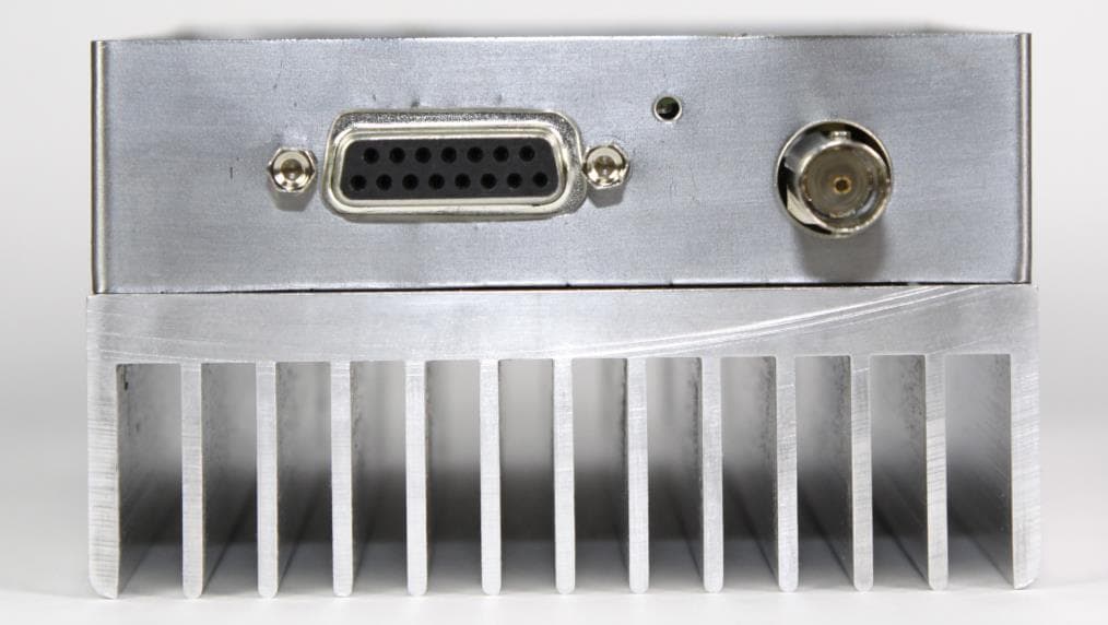
AIERIT34-4650
Dec 10, 2015UHF Transceiver Module
Equipment Class
TNB - Licensed Non-Broadcast Station Transmitter