AJTAATCSSR-24Advanced Automatic Train Control - Spread Spectrum
GE Transportation Systems Global Signaling LLC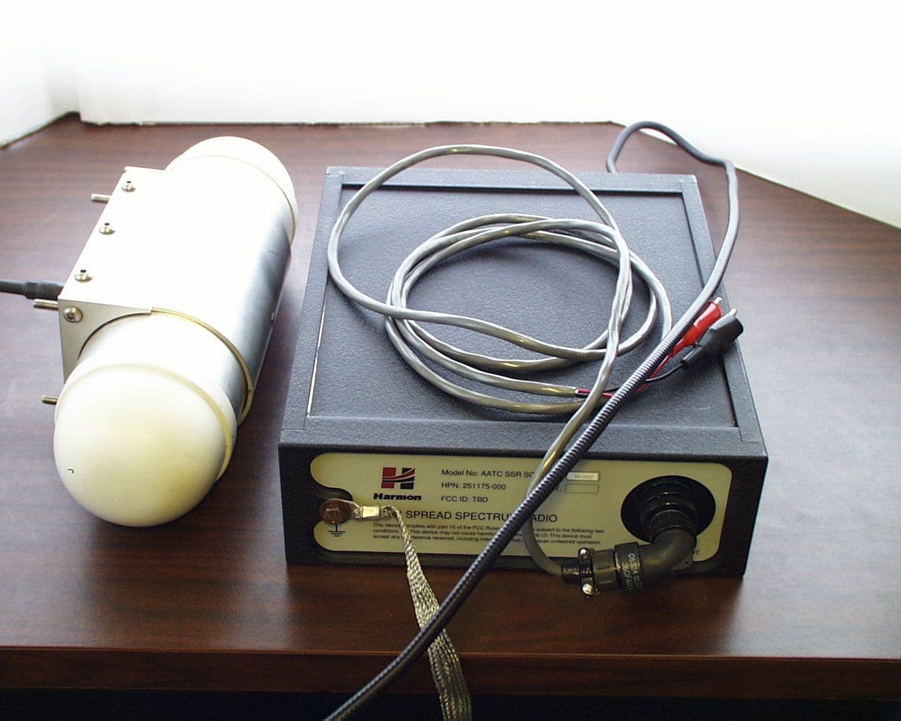
Click to zoom
Application Details
- Equipment Class
- DSS - Part 15 Spread Spectrum Transmitter
- Date of Grant
- Sep 12, 2000
- Application Purpose
- Original Equipment
- Date of Application
- Jun 19, 2000
- Equipment Note
- Advanced Automatic Train Control - Spread Spectrum
- Frequency Range
- 2400.00000000 - 2483.50000000
- Country
- United States
Documents & Files

Document Text
Text extracted from the exhibit documents filed with the FCC. Open a document above to read the original.
Users Manual
COPYRIGHTEDAATC SPREAD SPECTRUM RADIO User Manual See Cover SheetRevision : USER MANUAL FOR AATC SPREAD SPECTRUM RADIO HARMON INDUSTRIES, INC GRAIN VALLEY, MO. Copyright 2000 Harmon Industries Inc. All Rights Reserved The contents of this document may not be reproduced in whole or part without the written consent of the copyright owner. COPYRIGHTEDAATC SPREAD SPECTRUM RADIO User Manual See Cover SheetRevision : TABLE OF CONTENTS COPYRIGHTEDAATC SPREAD SPECTRUM RADIO User Manual See Cover SheetRevision : SCOPE This User Manual describes the Harmon Advanced Automatic Train Control (AATC) Spread Spectrum Radio (SSR) portion of the AATC Radio Set (RS), its installation, and conditions of usage. APPLICABLE DOCUMENTS The following Government regulations form a part of this User Manual to the extent specified herein. In the event of a conflict between the regulations referenced herein and the contents of this manual, the regulations shall be considered a superseding requirement. Title 29, Code of FederalOccupational Safety and Health Standards Regulations, Chapter XVII Part 1910, Subpart G, I, & L Title 47, Code of FederalFederal Communication Commission Rules Regulations, Part 15, Subpart C COPYRIGHTEDAATC SPREAD SPECTRUM RADIO User Manual See Cover SheetRevision : Advanced Automatic Train Control Spread Spectrum Radio (AATC-SSR) DESCRIPTION AATC-SSR Definition The AATC-SSR is a multi-functional digital data transmitter-receiver used for digital data communication and range measurement. The AATC-SSR with suitable antenna and mounting/installation kits is a Radio Set (RS) and can be used in a variety of rail vehicle and wayside configurations. The AATC-SSR is identical in all RS configurations. Only the differences in the mounting and installation kit (Antenna, Product Identification Module (PIM), and mounting) define a specific RS configuration and it’s use. The Product Identification Module is a serial electrically erasable programmable read only memory (EEPROM) which provides the radio with it’s configuration type i.e. vehicle, or wayside radio. The AATC-SSR is designed specifically for the railroad environment and requires professional installation and operation. AATC-SSR Operation The AATC-SSR provides for data exchange between RSs, between the AATC-SSR and a Train Controller, and between the AATC-SSR and a Station Computer. The AATC-SSR has serial interface capability to a Global Positioning System (GPS) Receiver and the Radio Test Set (RTS), a specialized test equipment. The AATC-SSR operation is controlled by firmware (embedded software). The AATC- SSR hardware, in combination with this firmware, is designed for operation in a communications network of similar AATC-SSRs to perform train control or other similar applications. A network can contain as few as two AATC-SSRs or as many as several hundred AATC-SSRs. The firmware is specifically designed to support networks of AATC-SSRs spread out along railways or tunnels, where multiple radio frequency (RF) links may need to be cascaded to provide communications from a source to a remote destination. Highly reliable communications is provided through a variety of techniques including spread spectrum and redundant RF channels. Using the RF communications signals, the AATC-SSRs cooperatively measure the range between pairs of AATC-SSRs. The range measurements are reported to a control station, which is connected to one of the AATC-SSRs in a network, and the Control Station can use these ranges to establish and track the locations of AATC-SSR equipped vehicles. The AATC-SSR operates in the 2400 MHz to 2483.5 MHz frequency band. Its transmit center frequency can be controlled to be anywhere from 2423.75 MHz to 2462.75 MHz in 1 MHz steps. The AATC-SSRs share the RF band using a combination of time division, frequency division, and code division multiple access techniques. The communications network structure is managed by a control station computer, which assigns time and frequency resources to each of the AATC-SSRs. COPYRIGHTEDAATC SPREAD SPECTRUM RADIO User Manual See Cover SheetRevision : COPYRIGHTEDAATC SPREAD SPECTRUM RADIO User Manual See Cover SheetRevision : The AATC-SSR consists of three major functional modules and the external interfaces shown in Figure 1. AATC-SSR MV FUNCTION SP FUNCTION RFA FUNCTION MP FUNCTION T&C FUNCTION POWER INTERFACE TO ALL FUNCTIONS FRONT PANEL FUNCTION SERIAL INTERFACE INDICATORS SMP FUNCTION ANTENNA INTERFACE POWER DISTRIBUTION FUNCTION RADIO TEST SET PORT Figure 1 AATC-SSR Block Diagram External Physical Interfaces The AATC-SSR implements the following interfaces, shown in Figure 1. The Power Interface is located on the rear of the unit while the all other interfaces are located on the front of the AATC-SSR. The operator interface allows the operator to monitor operation of the AATC-SSR. The remaining interfaces are external connections for the Antenna, Serial Interface (GPS Receiver, Train Controller or Station Computer), Radio Test Set, and Power. Operator Interface The AATC-SSR provides the operator with the following indicators visible from either the top or front of the AATC-SSR: Power The POWER indicator is a green LED which provides the operator with an indication that proper power is applied to the AATC-SSR. COPYRIGHTEDAATC SPREAD SPECTRUM RADIO User Manual See Cover SheetRevision : Fault The FAULT indicator is a red LED which provides the operator with an indication that the AATC-SSR’s firmware has encountered a failure and is not ready for operation. This indicator is momentarily turned on during power –up. Mode The MODE indicator is a yellow LED. The indicator provides the following indications: In Power Up mode, during the operational checks, the indicator will be ON. Otherwise, the indicator will, under firmware control, blink ON and OFF in accordance with the following ratios: Net Acquisition7 ON/ 1 OFF Time Sync3 ON/ 1 OFF Time Stabilized1 ON/ 1 OFF A Assignment Received1 ON/ 3 OFF B Assig…
Text truncated - open the document above for the full version.
Cover Letter(s)
June 20, 2000 Federal Communications Commission Equipment Approval Services P.O. Box 35815 Pittsburgh, PA 15251-3315 Applicant:HARMON INDUSTRIES, INC. Equipment:FCC ID: ajtaatcssr-24 FCC Rules:Parts 2 and 15.247 Gentlemen: It is requested that the schematics of the application be held confidential per Section 0.459. The section 5 exhibits (Schematics) are to be held in confidence with the FCC. Specialized technology and techniques incorporated into the design maybe depicted in the schematics. It is with this consideration that the request for confidentiality be made. Specifically all the schematic drawings uploaded as exhibit 5 shall be held in confidence. The special fee for request of confidentiality will be submitted with the application. Should you require any further information, please contact the undersigned. Thank you for your consideration in this matter. Sincerely, Scot Rogers Rogers Labs, Inc. ROGERS LABS, INC. 4405 West 259 th Terrace Louisburg, KS 66053 Phone / Fax (913) 837-3214
Cover Letter(s)
June 20, 2000 Federal Communications Commission Equipment Approval Services P.O. Box 35815 Pittsburgh, PA 15251-3315 Applicant:Harmon Industries, Inc. Equipment:FCC ID: ajtaatcssr-24 FCC Rules:Parts 2 and 15.247 Gentlemen: Please find enclosed Application Form 159 with filing fees attached for Certification of Intentional Radiators operated at 1090.00 MHz. The 731 form and application have been electronically submitted and any attachments will be up loaded to the FCC web site. It is requested that the schematics of the application be held confidential per Section 0.459. A statement of confidentiality will be attached with the schematics at the time of submittal. The special fee for request of confidentiality will be submitted with the application. Should you require any further information, please contact the undersigned. Thank you for your consideration in this matter. Sincerely, Scot Rogers Rogers Labs, Inc. Enclosures ROGERS LABS, INC. 4405 West 259 th Terrace Louisburg, KS 66053 Phone / Fax (913) 837-3214
Operational Description
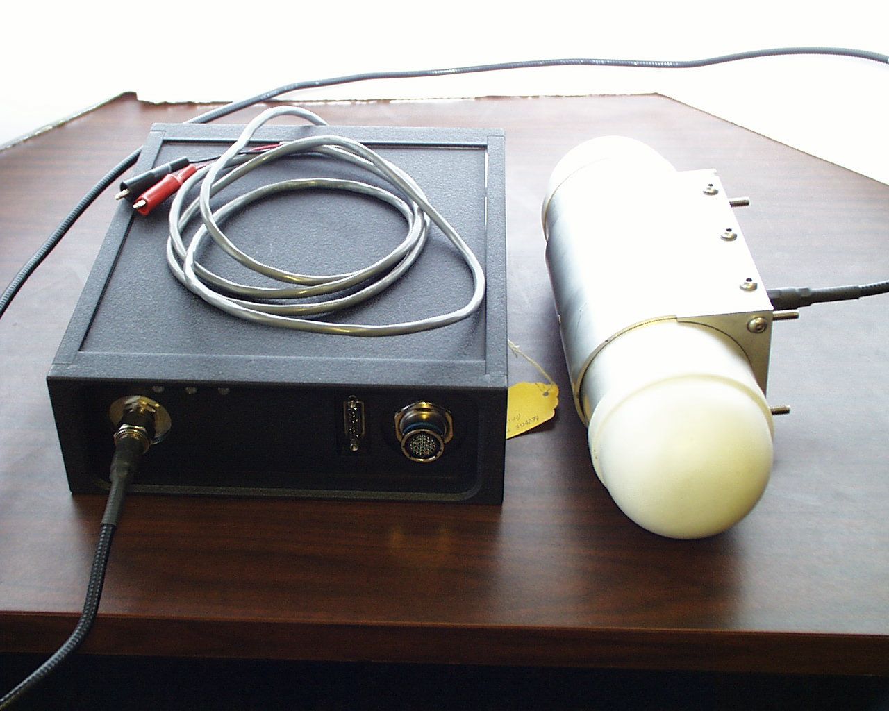
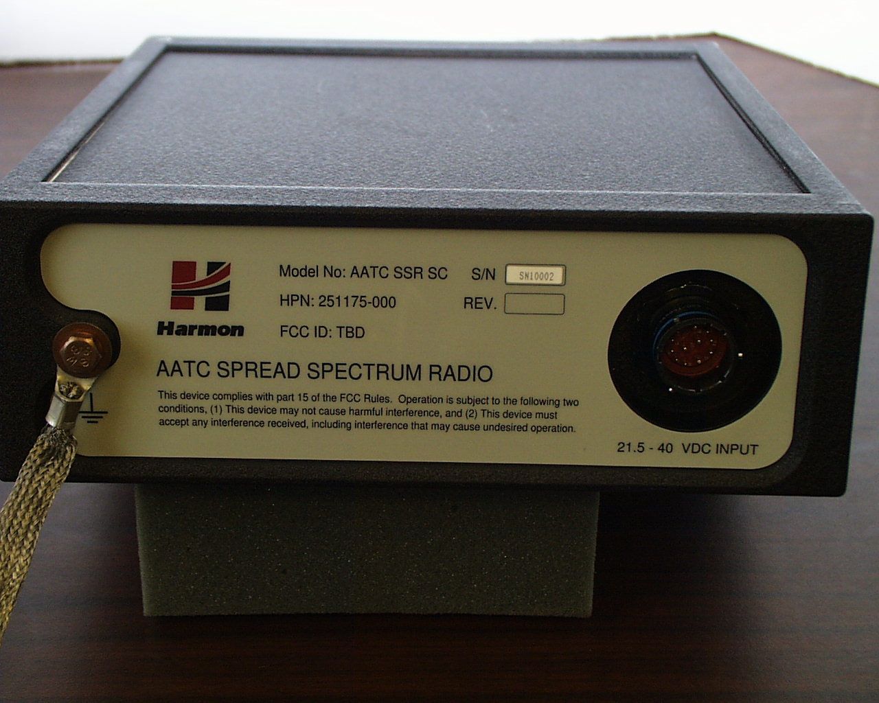
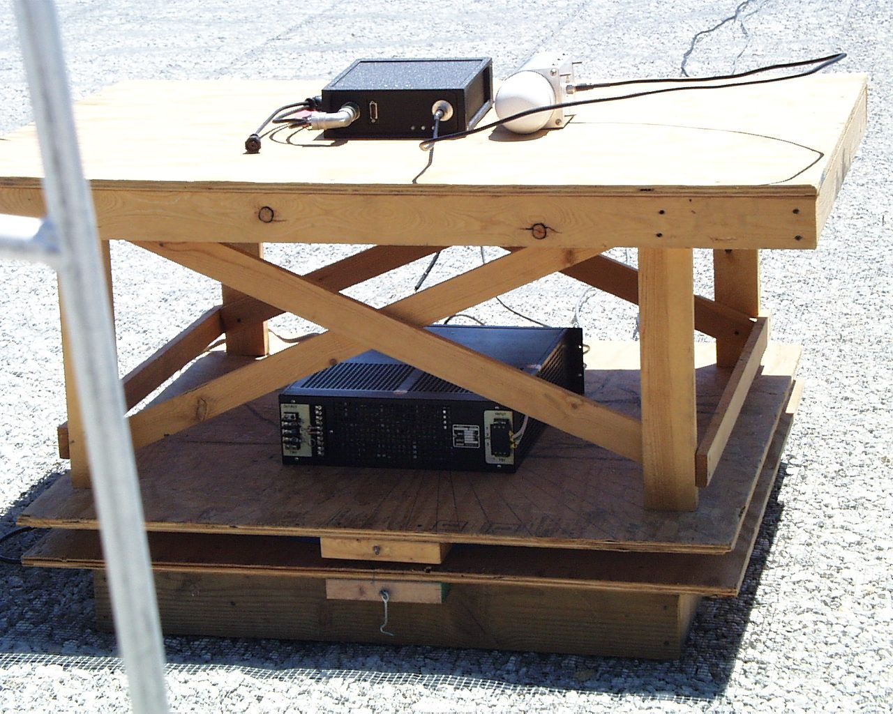
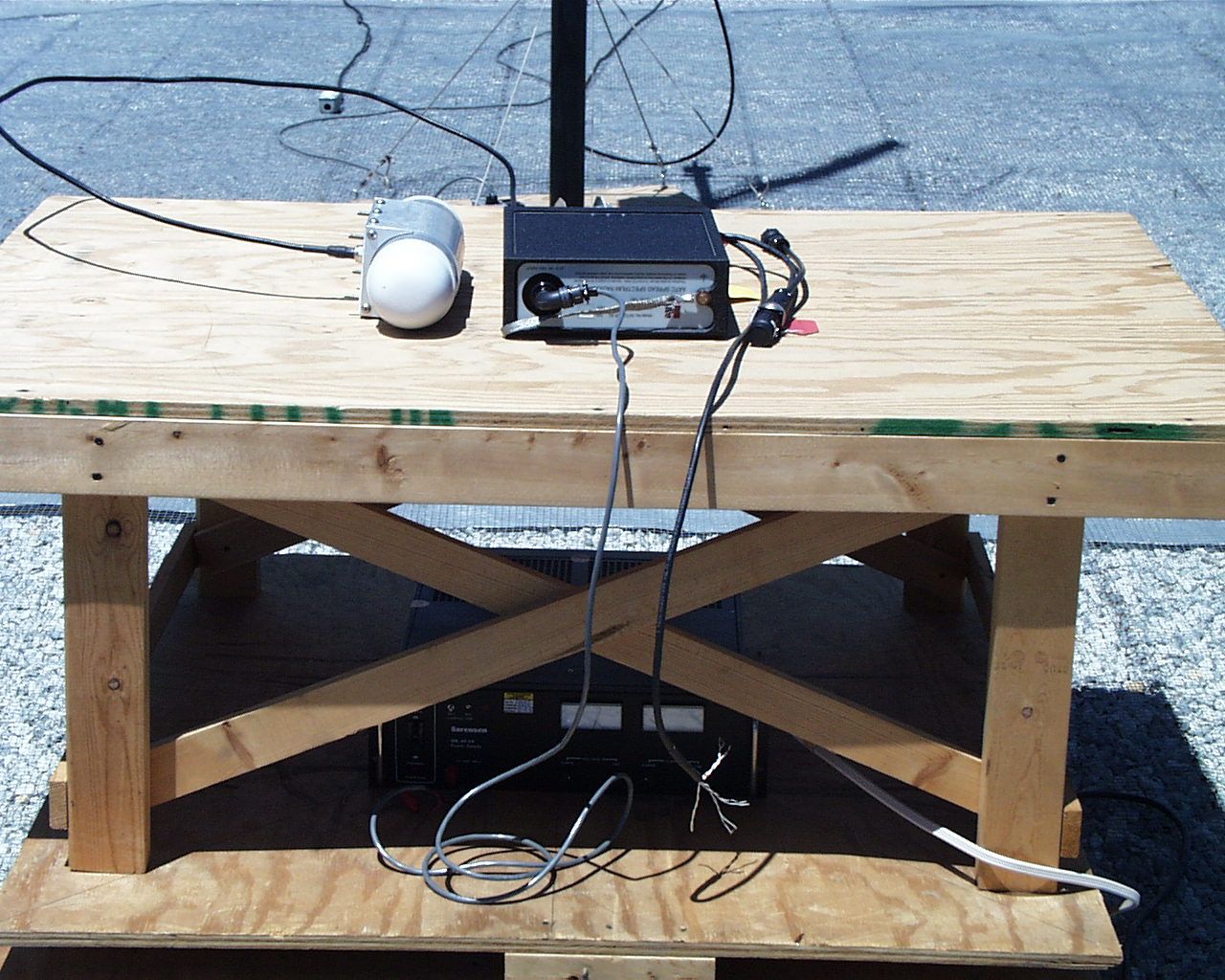
Advanced Automatic Train Control Spread Spectrum Radio (AATC-SSR) DESCRIPTION AATC-SSR Definition The AATC-SSR is a multi-functional digital data transmitter-receiver used for digital data communication and range measurement. The AATC-SSR with suitable antenna and mounting/installation kits is a Radio Set (RS) and can be used in a variety of rail vehicle and wayside configurations. The AATC-SSR is identical in all RS configurations. Only the differences in the mounting and installation kit (Antenna, Product Identification Module (PIM), and mounting) define a specific RS configuration and it’s use. The Product Identification Module is a serial electrically erasable programmable read only memory (EEPROM) which provides the radio with it’s configuration type i.e. vehicle, or wayside radio. The AATC-SSR is designed specifically for the railroad environment and requires professional installation and operation. AATC-SSR Operation The AATC-SSR provides for data exchange between RSs, between the AATC-SSR and a Train Controller, and between the AATC-SSR and a Station Computer. The AATC-SSR has serial interface capability to a Global Positioning System (GPS) Receiver and the Radio Test Set (RTS), a specialized test equipment. The AATC-SSR operation is controlled by firmware (embedded software). The AATC-SSR hardware, in combination with this firmware, is designed for operation in a communications network of similar AATC-SSRs to perform train control or other similar applications. A network can contain as few as two AATC-SSRs or as many as several hundred AATC-SSRs. The firmware is specifically designed to support networks of AATC-SSRs spread out along railways or tunnels, where multiple radio frequency (RF) links may need to be cascaded to provide communications from a source to a remote destination. Highly reliable communications is provided through a variety of techniques including spread spectrum and redundant RF channels. Using the RF communications signals, the AATC-SSRs cooperatively measure the range between pairs of AATC-SSRs. The range measurements are reported to a control station, which is connected to one of the AATC-SSRs in a network, and the Control Station can use these ranges to establish and track the locations of AATC-SSR equipped vehicles. The AATC-SSR operates in the 2400 MHz to 2483.5 MHz frequency band. Its transmit center frequency can be controlled to be anywhere from 2423.75 MHz to 2462.75 MHz in 1 MHz steps. The AATC-SSRs share the RF band using a combination of time division, frequency division, and code division multiple access techniques. The communications network structure is managed by a control station computer, which assigns time and frequency resources to each of the AATC-SSRs.
Parts List/Tune Up Info
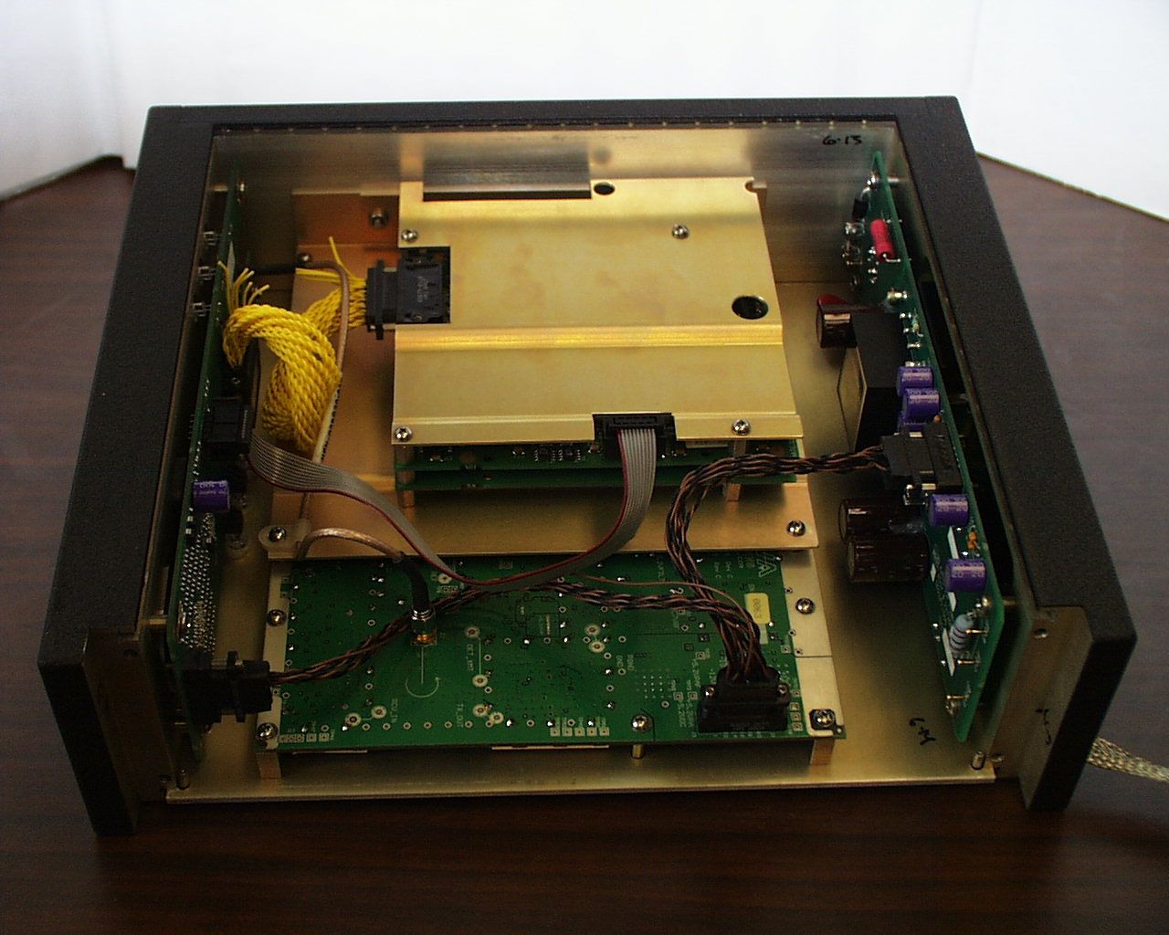
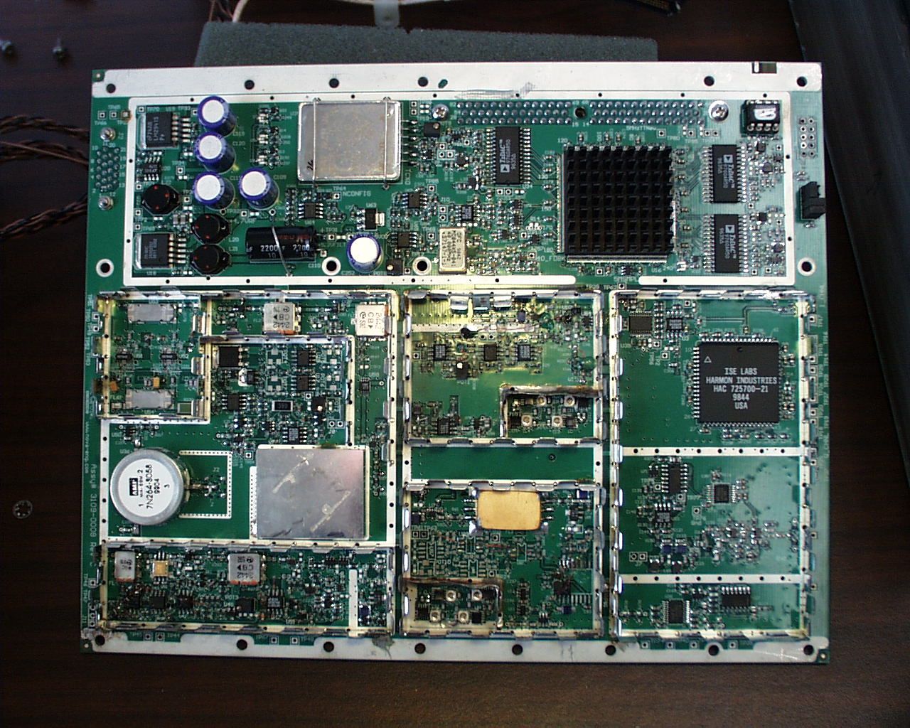
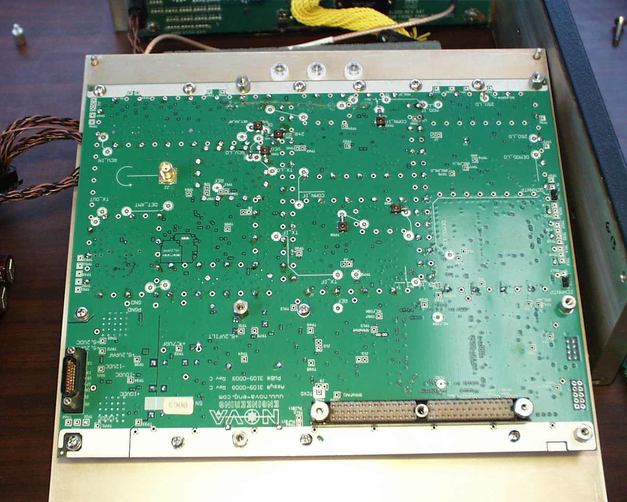
Radio Frequency Assembly (RFA) Description: The Antenna port (J3) uses a circulator to direct the receive and transmit signals. In transmit mode, the RFA performs direct-sequence spreading using 21 chips per message symbol. A 250 MHz local oscillator (LO) and 248.75 MHz Surface-Acoustic Wave (SAW) filter are used to perform the continuous-phase-shift-modulation (CPSM) which converts the digital signal to a spread spectrum signal at the RFA’s 248.75 MHz intermediate frequency (IF). After the CPSM modulation, the spread signal is upconverted to one of 40 center frequencies at 1 MHz intervals from 2423.75 MHz to 2462.75 MHz using an appropriate LO frequency between 2175 MHz and 2214 MHz. This later LO is designated the 2.2 GHz LO to differentiate it from the 250 MHz LO. The 2423.75 MHz to 2462.75 MHz ISM band signal is then filtered to suppress undesired components of the frequency conversion, and amplified to 28.5 dBm at the Antenna port (J3). The amplifier incorporates Automatic Gain Control (AGC) to maintain the desired level of 28.5 dBm +/-1.0 dB across the frequency band and environmental conditions. In receive mode, the incoming 2423.75 MHz to 2462.75 MHz ISM band signal from the antenna port (J3) is filtered to reject out-of-band signals and amplified to establish a low noise factor. Improved dynamic range on receive, as well as protection of the receiver during transmit, is provided by an RF AGC loop using a high dynamic range semiconductor attenuator. The signal is then down converted to the 248.75 MHz IF using the same 2.2 GHz LO developed for the transmitter. In addition, switches reconfigure the 248.75 MHz AGC’d IF amplifier containing the SAW filter between the receiver and transmitter functions. The 248.75 MHz IF amplifier output is demodulated to 1.25 MHz I and Q signals using the 250 MHz LO. I and Q signal is digitized using a 2-bit adaptive A/D converter, and are then output to the Signal and Message Processor (SMP) module – the I-channel being the PN encoded data and the Q-channel used for 250 MHz LO phase adjustment decision-making. All LO’s as well as the spread spectrum modulation are developed from a precision 32.514 MHz reference frequency oscillator. The 32.514 MHz reference source is converted into three 5 MHz sources, each with the capability to phase and frequency track the appropriate system timing, using individual Numerically Controlled Oscillators (NCO). One of these 5 MHz sources is the Time Track which is synchronized with the spread spectrum chip rate. Another is the synthesized 250 MHz LO reference and the third is the reference for the 2.2 GHz LO. This later LO reference is created by first synthesizing a 40 MHz reference from the 5 MHz reference using a 40 MHz voltage controlled crystal oscillator (VCXO). The 40 MHz VCXO is then divided to the 2.2 GHz LO synthesizer reference frequency and phase lock to the 2.2 GHz LO variable divider, achieving 1 MHz channel spacing.
RF Exposure Info
ROGERS LABS, INC.Harmon Industries, Inc. 4405 W. 259th TerraceMODEL: AATC-SSR Louisburg, KS 66053Test #: 000614FCCID#: AJTAATCSSR-24 Phone/Fax: (913) 837-3214Test to: FCC Parts 2 and 15cPage 1 of 1 CERTIFICATION\HarmonAATC24SAR 08/28/2000 CALCULATED SAR for UNCONTROLLED, GENERAL POPULATION S = PG/(4πR 2 ) Where S = power density in mw/cm 2 P = input power to antenna in mw. G = power gain of antenna R = distance from antenna in cm. For a minimum distance of 3 meters and 2 watt operation with a 10-dB gain antenna, S is: S = 1000(10)/(4π(300) 2 ) = 0.0088 mw/cm 2 This is within the requirements of 1.0 mw/cm 2 . There is only one antenna available for use with this system. It is professionally installed and modification or substitution is not an option. The typical gain of the antenna is 6 dB and will always be less than 10 dB. A picture of the antenna is included in the report.
RF Exposure Info
ROGERS LABS, INC.Harmon Industries, Inc. 4405 W. 259th TerraceMODEL: AATC-SSR Louisburg, KS 66053Test #: 000614FCCID#: AJTAATCSSR-24 Phone/Fax: (913) 837-3214Test to: FCC Parts 2 and 15cPage 1 of 3 CERTIFICATION\HarmonAATC24SAR 09/05/2000 CALCULATED SAR for UNCONTROLLED, GENERAL POPULATION S = PG/(4πR 2 ) Where S = power density in mw/cm 2 P = input power to antenna in mw. G = power gain of antenna R = distance from antenna in cm. For a minimum distance of 3 meters and 1 watt operation with a 10-dB gain antenna, S is: S = 1000(10)/(4π(300) 2 ) = 0.0088 mw/cm 2 This is within the requirements of 1.0 mw/cm 2 . There is only one antenna available for use with this system. It is professionally installed and modification or substitution is not an option. The typical gain of the antenna is less than 6 dB and will always be less than 10 dB. A picture of the antenna is included in the report. Questions from the FCC 1. Filing is requesting for 1.0 W peak conducted output for this transmitter. There does not appear to be any peak conducted output measurement results in the test report. The RF exposure info is based on 2 W output with antenna gain up to 10 dBi. Maximum allowed output by the rules is 1.0 W peak and output reduction is required when antenna gain is higher than 6 dBi; please clarify. REPLY Figure 14 on page 24 of the report shows a plot of the spectrum analyzer screen with antenna conducted emissions measurement. There was a 10dB attenuator and 2dB of cable loss. This equates to a 29.5 dBm output and falls within 0.5 dB of 1 Watt. The unit produces a maximum of 1-Watt output power. The equation shows 1000 mW (1watt) and is correct for the equation. The 10 dB of antenna gain was used to demonstrate how far BELOW the limits the unit is for maximum exposure limits. This unit uses a one-quarter wave spike antenna, mounted inside of an aluminum cylinder approximately 4 inches in diameter and twelve inches long. This gives the antenna a VERY focused beam width, and is mounted to the TOP of a TRAIN ENGINE. The units are required to be professionally installed as mentioned at least three times in the manual and the requirements of 15.203 are met. 2. MPE info indicated there is only one antenna available for this system, which described the typical antenna gain is 6 dBi but not exceeding 10 dBi. It also indicates that a picture of the antenna is included in the report. Please provide specific information on the antenna type and gain. It is not clear according to the photos submitted whether the cylindrical structure next to the transmitter is the antenna. It seems to have radomes on both ends of the cylinder, please clarify. REPLY The statement should read LESS THAN 6 dB of gain. Again, this was used for MPE demonstration purposes only. The radio frequency exposure is not what is going to injure someone in the path of this TRAIN. The antenna is a metal cylinder with plastic covers on both ends to keep foreign objects from damaging the spike antenna inside. Refer to the pictures below showing the antenna removed from the cylinder and a picture down the inside of the tube. ROGERS LABS, INC.Harmon Industries, Inc. 4405 W. 259th TerraceMODEL: AATC-SSR Louisburg, KS 66053Test #: 000614FCCID#: AJTAATCSSR-24 Phone/Fax: (913) 837-3214Test to: FCC Parts 2 and 15cPage 2 of 3 CERTIFICATION\HarmonAATC24SAR 09/05/2000 ROGERS LABS, INC.Harmon Industries, Inc. 4405 W. 259th TerraceMODEL: AATC-SSR Louisburg, KS 66053Test #: 000614FCCID#: AJTAATCSSR-24 Phone/Fax: (913) 837-3214Test to: FCC Parts 2 and 15cPage 3 of 3 CERTIFICATION\HarmonAATC24SAR 09/05/2000 3. The MPE info used a separation of 3 meters between the antenna and persons. Please provide installation instructions and requirements to support the 3 meter distance used in the MPE estimation. If applicable, revise the MPE estimations using the correct distance and antenna gain. The applicable antenna installation instructions and operating requirements should be included in the users manual for users and installers to satisfy RF exposure compliance. Please revise and submit the relevant pages of the manual. Note: Output is Unknown, need peak conducted output results. REPLY The length of three meters is applicable due to the fact that a TRAIN ENGINE is taller than nine feet three inches. The antenna is mounted, by professional installers qualified by the railway system, to the TOP of the train engine, in a horizontal fashion, with the beam pointing to the front and rear of the train. The users of the radio are located inside the personnel compartment of the engine. They are protected from exposure due to the location of the antenna, physical separation and steel walls between them and the antenna element. The professional installers are educated on the practices of antenna installation and are not required to energize the antenna while mounting it to the engine.
Test Report
TEST REPORT For APPLICATION of CERTIFICATION For HARMON INDUSTRIES, INC. Dillingham & Argo Road Grain Valley, MO 64029 Phone: (816) 650-6171 Jeff Kleoppel, Senior Design Engineer MODEL: AATC-SSR Advanced Automatic Train Control - Spread Spectrum Radio Frequency 2400 - 2483.5 MHz FCC ID: AJTAATCSSR-24 Test Date:June 15, 2000 Certification Date: June 15, 2000 Certifying Engineer: Scot D. Rogers ROGERS LABS, INC. 4405 West 259 th Terrace Louisburg, KS 66053 Phone: (913) 837-3214 FAX: (913) 837-3214 This report shall not be reproduced except in full, without the written approval of the laboratory. This report must not be used by the client to claim product endorsement by NVLAP or any agency of the U.S. Government. ROGERS LABS, INC. 4405 West 259 th Terrace Louisburg, KS 66053 Phone / Fax (913) 837-3214 NVLAP Accredited LaboratoryNVLAP Lab Code: 200087-0 ROGERS LABS, INC.Harmon Industries, Inc. 4405 W. 259th TerraceMODEL: AATC-SSR Louisburg, KS 66053Test #: 000614FCCID#: AJTAATCSSR-24 Phone/Fax: (913) 837-3214Test to: FCC Parts 2 and 15cPage 2 of 37 CERTIFICATION\HarmonAATC-SSR 06/20/2000 TABLE OF CONTENTS FORWARD:.....................................................................................................................3 1)APPLICABLE STANDARDS & TEST PROCEDURES............................................3 2)APPLICATION FOR CERTIFICATION PER 2.1033(B)............................................4 3)EQUIPMENT TESTED..............................................................................................5 4)EQUIPMENT FUNCTION AND TESTING PROCEDURES......................................5 5)EQUIPMENT AND CABLE CONFIGURATIONS......................................................5 Conducted Emission Test Procedure................................................................................................................5 Radiated Emission Test Procedure...................................................................................................................5 6)LIST OF TEST EQUIPMENT....................................................................................6 7)UNITS OF MEASUREMENTS..................................................................................7 8)TEST SITE LOCATIONS..........................................................................................7 9)SUBPART B – UNINTENTIONAL RADIATORS......................................................7 Conducted EMI...................................................................................................................................................7 Radiated EMI......................................................................................................................................................8 Data: EUT and System Radiated Emissions (6 Highest) :................................................................................10 Summary of Results for Conducted Emissions:................................................................................................10 Summary of Results for Radiated Emissions:...................................................................................................11 Statement of Modifications:..............................................................................................................................11 10)SUBPART C - INTENTIONAL RADIATORS.........................................................11 15.203 Antenna Requirements........................................................................................................................11 Restricted Bands of Operation Per 15.205.....................................................................................................12 Data 15.205:......................................................................................................................................................12 15.209 Radiated Emissions Limits; General Requirements..........................................................................13 Radiated EMI....................................................................................................................................................13 Data 15.209:......................................................................................................................................................14 Summary of Results for Radiated Emissions:...................................................................................................14 15.247 Operation in the Band 2400-2483.5 MHz..........................................................................................14 Summary of Results for Radiated Emissions of Intentional Radiator:..............................................................24 Statement of Modifications:..............................................................................................................................25 APPENDIX....................................................................................................................26 NVLAP Accredited LaboratoryNVLAP Lab Code: 200087-0 ROGERS LABS, INC.Harmon Industries, Inc. 4405 W. 259th TerraceMODEL: AATC-SSR Louisburg, KS 66053Test #: 000614FCCID#: AJTAATCSSR-24 Phone/Fax: (913) 837-3214Test to: FCC Parts 2 and 15cPage 3 of 37 CERTIFICATION\HarmonAATC-SSR 06/20/2000 FORWARD: The following is submitted for consideration in obtaining a Grant of Certification for low power intentional radiators operated under CFR 47, paragraph 15.247(a)(2). Name of Applicant: HARMON INDUSTRIES, INC. Dillingham & Argo Road Grain Valley, MO 64029 Model: AATC-SSR FCC I.D.: AJTAATCSSR-24 Frequency Range: 2400 MHz to 2483.5 MHz Operating Power: 1 Watt 1)Applicable Standards & Test Procedures a)In accordance with the Federal Communications Code of Federal Regulations, dated October 1, 1999, Part 2, Subpart J, Paragraphs 2.907, 2.911, 2.913, 2.925, 2.926, 2.1031 through 2.1057, Part 15C Paragraph 15.247, and FCC Document FCC98-58 the following i…
Text truncated - open the document above for the full version.
Contact Information
Applicant
Jeff Kleoppel(Senior Design Engineer)
816 650-6171
Technical Contact
Rogers Labs, IncScot Rogers
[email protected]913 837-3214
4405 West 259th Terrace · Louisburg, Kansas · United States
Non-Technical Contact
Rogers Labs, Inc.Scot Rogers
[email protected]913 837-3214
Test Firm
Rogers Labs, Inc.Scot Rogers
Technical Specifications
| # | Rule Parts | Frequency Range | Power Output |
|---|---|---|---|
| 1 | 15C | 2.40 GHz - 2.48 GHz | 891.00 mW |
Other Applications from GE Transportation Systems Global Signaling LLC

AJT-GS12RII-V1
Jun 18, 2002VHF FM Transceiver
Equipment Class
TNB - Licensed Non-Broadcast Station TransmitterAJTH12RT-U2
Aug 12, 1996TNB - Licensed Non-Broadcast Station Transmitter
Equipment Class
TNB - Licensed Non-Broadcast Station TransmitterAJTH12RT-U1
Aug 12, 1996TNB - Licensed Non-Broadcast Station Transmitter
Equipment Class
TNB - Licensed Non-Broadcast Station TransmitterAJTH12RT-U3
Aug 04, 1996TNB - Licensed Non-Broadcast Station Transmitter
Equipment Class
TNB - Licensed Non-Broadcast Station TransmitterAJTHMCPT-900
Apr 06, 1995TNB - Licensed Non-Broadcast Station Transmitter
Equipment Class
TNB - Licensed Non-Broadcast Station Transmitter