AMWOVP2001610888Marine VHF Portable Transceiver
Uniden America Corporation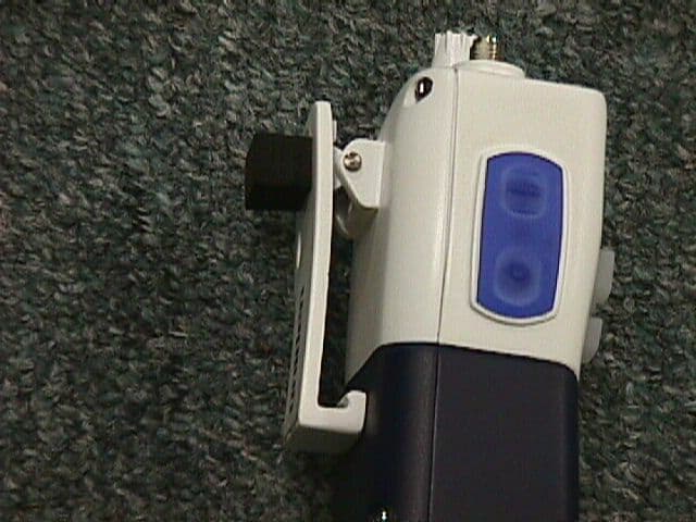
Click to zoom
Application Details
- Equipment Class
- TNF - Licensed Non-Broadcast Transmitter Held to Face
- Date of Grant
- Aug 16, 2001
- Application Purpose
- Original Equipment
- Date of Application
- Jun 11, 2001
- Equipment Note
- Marine VHF Portable Transceiver
- Frequency Range
- 156.02500000 - 157.42500000
- Company
- Uniden America Corporation
- Country
- United States
Documents & Files
Document Text
Text extracted from the exhibit documents filed with the FCC. Open a document above to read the original.
Users Manual
ATLANTIS Atlantis_OM.qxd 06/08/2001 4:51 PM Page 1 Three- Year Limited Warranty Important:Evidence of original purchase is required for warranty service. WARRANTOR: UNIDEN AMERICA CORPORATION (Uniden) ELEMENTS OF WARRANTY: Uniden warrants for three years, to the original retail owner, this Product excluding the NiMH battery pack to be free from defects in materials and craftsmanship with only the limitations or exclusions set out below. Uniden warrants for 12 months, to the original retail owner, the NiMH battery pack to be free from defects in material and craftsmanship with only the limitations or exclusions set out below. WARRANTY DURATION:This warranty to the original user shall terminate and be of no further effect 36 months (12 months for the NiMH battery pack) after the date of original retail sale. The warranty is invalid if the Product is (A) damaged or not maintained as reasonable or necessary, (B) modified, altered, or used as part of any conversion kits, subassemblies, or any configurations not sold by Uniden, (C) improperly installed, (D) serviced or repaired by someone other than an authorized Uniden service center for a defect or malfunction covered by this warranty, (E) used in any conjunction with equipment or parts or as part of any system not manufactured by Uniden, or (F) installed or programmed by anyone other than as detailed by the Owner's Manual for this product. STATEMENT OF REMEDY: In the event that the product does not conform to this warranty at any time while this warranty is in effect, warrantor will either, at its option, repair or replace the defective unit and return it to you without charge for parts, service, or any other cost (except shipping and handling) incurred by warrantor or its representatives in connection with the performance of this warranty. Warrantor, at its option, may replace the unit with a new or refurbished unit. THE LIMITED WARRANTY SET FORTH ABOVE IS THE SOLE AND ENTIRE WARRANTY PERTAINING TO THE PRODUCT AND IS IN LIEU OF AND EXCLUDES ALL OTHER WARRANTIES OF ANY NATURE WHATSO- EVER, WHETHER EXPRESS, IMPLIED OR ARISING BY OPERATION OF LAW, INCLUDING, BUT NOT LIMITED TO ANY IMPLIED WARRANTIES OF MERCHANTABILITY OR FITNESS FOR A PARTICULAR PURPOSE. THIS WARRANTY DOES NOT COVER OR PROVIDE FOR THE REIMBURSEMENT OR PAYMENT OF INCIDENTAL OR CONSEQUENTIAL DAMAGES. Some states do not allow this exclusion or limitation of incidental or consequential damages so the above limitation or exclusion may not apply to you. LEGAL REMEDIES: This warranty gives you specific legal rights, and you may also have other rights which vary from state to state. This warranty is void outside the United States of America. PROCEDURE FOR OBTAINING PERFORMANCE OF WARRANTY: If, after following the instructions in the Owner's Manual you are certain that the Product is defective, pack the Product carefully (preferably in its original packaging). The Product should include all parts and accessories originally packaged with the Product. Include evidence of original purchase and a note describing the defect that has caused you to return it. The Product should be shipped freight prepaid, by traceable means, to warrantor at: Uniden America Corporation Parts and Service Division 4700 Amon Carter Boulevard Fort Worth, TX 76155 (800) 554-3988, 7AM to 5PM Central Time Monday through Friday Atlantis_OM.qxd 06/08/2001 4:51 PM Page 2 1. Antenna 2. Belt Clip 3. PTT (Push to Talk) Key 4. Light/Lock Key 5. WX Mode/Weather Alert Button (WX ALERT) 6. USA/International/ Canadian Button (UIC) 7. Memory Button (MEM) 8. Microphone 9. Volume/Power Knob 10. Squelch Knob 11. LCD Display 12. Scan Button (Scan) 13. 16/9-Triple Watch Button (16/9 TRI) 14. Channel Up Button (s) 15. TX Power Button (1/5W) Invert Display Controls and Indicators 16. Channel Down Button (t) 17. Speaker 18. Battery Pack A. TX Indicator B. TX Power Indicator C. Channel Number Display D. Battery Indicator E. USA/International/ Canadian (US/INT/CAN) Channel Indicator F. Memory Indicator G. Triple Watch Indicator H. Weather Mode Indicator I. Weather Alert Indicator J. Lock Indicator K. Scan Indicator Atlantis_OM.qxd 06/08/2001 4:51 PM Page 3 Warning! +The ATLANTIS is watertight only when both the antenna and the battery are properly attached. +Do not operate the transmitter of any radio equipment near electrical blasting caps or in an explosive atmosphere. +Do not let children operate any transmitter-equipped radio equip- ment without proper supervision. +Have your radio equipment serviced by a qualified technician. +Do not operate the transmitter of any radio equipment with the antenna touching or close to the eyes, face, or exposed body parts. NiMH Battery Pack Warning +This equipment contains a NiMH Battery Pack. +The NiMH Battery Pack contained in this equipment may explode if disposed of in a fire. +Do not short-circuit the Battery Pack. +Do not charge the NiMH Battery Pack used in this equipment with any charger other than the one designed to charge this Battery Pack. Using another charger may damage the Battery Pack or cause the Battery Pack to explode. +NiMH batteries must be disposed of properly. Atlantis_OM.qxd 06/08/2001 4:51 PM Page 4 Contents FCC Notice . . . . . . . . . . . . . . . . . . .2 Introduction . . . . . . . . . . . . . . . . . .3 Features . . . . . . . . . . . . . . . . . . . .3 Technical Support and Service . . . . .4 Maritime Radio Service Operation . .4 Parts and Accessories . . . . . . . . . .5 Getting Started . . . . . . . . . . . . . . . .6 Mounting the cradle holder . . . . . . .6 Attaching the Antenna . . . . . . . . . . .6 Attaching the Battery Pack . . . . . . .7 Attaching the Spacer . . . . . . . . . . .8 Charging the Battery Pack . . . . . . . .9 Operation . . . . . . . . . . . . . . . . . . .10 Turning on the Unit and Setting Squelch . . . . . . . . . . .10 Selecting a Channel . . . . . . . . . . .11 One-touch Channel 16/9 . . . . . . . .11 Triple Watch . . . . . . . . . . . . . . . . .…
Text truncated - open the document above for the full version.
Users Manual
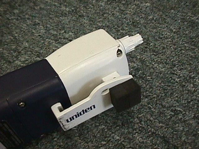
Attaching the spacers to the beltclip when using the optional Speaker/Microphone Spacers are included to be used with the optional Speaker/Microphone. Both spacers mustbe affixed to the beltclip of your ATLANTIS radio. Clean the surface area of the beltclip thoroughly. Remove the backing from the spacers and attach them to the upper part of the beltclip. Warning: Do not operate your ATLANTIS radio when using the optional Speaker/Microphone unless both spacers are properly affixed behind the beltclip. In order to reduce the likelihood of excessive radio frequency exposure, the spacers are provided for you to increase the distance between the radio antenna and the human body when operating the radio while attached to your belt. Additional steps should be taken to maintain a separation distance of at least 1 inch (2.5 cm) between the antenna and the human body. NOTE: Please see the addendum page included with this product for further details. ADDENDUM TO PAGE 8 OF THE ATLANTIS OWNER’S MANUAL addendum_page 8.qxd 08/15/2001 5:45 PM Page 1
Users Manual
RF Exposure Safety Statement RF Exposure Notice : Do not operate this VHF handheld marine radio without first reading and complying with the warnings stated on this addendum and within the O/M. Failure to do so may result in illegal and unsafe operation. SAFETY INFORMATION Your wireless handheld portable transceiver contains a low power transmitter. When the Push-to-Talk (PTT) button is pushed, the transceiver sends out radio frequency (RF) signals. In August 1996, the Federal Communications Commission adopted RF exposure guidelines with safety levels for hand-held wireless devices. This device is authorized to operate at a duty factory not to exceed 50% (this corresponds to 50% transmission time and 50% reception time). CAUTION: To maintain compliance with the FCC’s RF exposure guidelines, this transmitter and its antenna must maintain a separation distance of at least 1 inch (2.5 centimeters) from your body when transmitting. Speak in a normal voice, with the antenna pointed up and away from the face at the required separation distance. CAUTION: When attaching the optional speaker microphone accessory, you must attach the two spacers that are included in this box. First, clean the top area of the belt clip with rubbing alcohol to remove any build up of dirt or oil. Second, the two spacers must be attached to the top portion of the belt clip as illustrated in the owners’ manual. This will reduce the amount of RF exposure to work in compliance with FCC guidelines. Use only the supplied antenna. Unauthorized antennas, modifications, or attachments could damage the transmitter, and may violate FCC regulations. UNIDEN AMERICA CORPORATION 4700 Amon Carter Blvd. Ft. Worth, TX 76155 NOTE: You must follow the illustration above and install the spacers as shown when using the optional speaker microp ho ne.
Block Diagram
Test Report S/N: 80.210510298.AMW FCC Part 80 Dates of Tests: May 25-31, 2001 Type Acceptance © 2001 PCTEST Lab FCC ID: AMWOVP2001610888 1 2-Way Portable VHF Marine Radio Transceiver (GMDSS) MEASUREMENT REPORT 1.1 Scope Measurement and determination of electromagnetic emissions (EME) of radio frequency devices including intentional and/or unintentional radiators for compliance with the technical rules and regulations of the Federal Communications Commission. General Information Applicant Name: UNIDEN ENGINEERING SERVICES Address: 416 Maetan-3 Dong, Paldal-Ku Suwon City, Kyungki-Do, 441-742, KOREA Attention: Mr. Wallace Oh, Engineering Manager Samsung Electronics America (QA Lab) • FCC ID: AMWOVP2001610888 • Quantity: Quantity production is planned • Emission Designators: 16K0F3E • Tx Frequency Range: 156.025 ~ 157.425MHz • Rx Frequency Range: 156.050 ~ 163.275MHz • Max. Output Power: 5.0 W (HI) / 1.0 W (LOW) • FCC Classification(s): VHF Hand-held Transmitter - GMDSS (GHH) • Equipment (EUT) Type: 2-Way Portable VHF Marine Radio Transceiver (GMDSS) • Modulation(s): FM • Frequency Tolerance: ± 0.0005% (5.0 ppm) • FCC Rule Part(s): §§§ 80, 2.983, 2.987 • Dates of Tests: May 25-31, 2001 • Place of Tests: PCTEST Lab, Columbia, MD U.S.A. • Test Report S/N: 80.210510298.AMW Note: This device complies with the applicable general performance standards under § 80.1101(b), & the specific performance standards under § 80.1101(c)(2) of the FCC’s Rules and Regulations. Test Report S/N: 80.210510298.AMW FCC Part 80 Dates of Tests: May 25-31, 2001 Type Acceptance © 2001 PCTEST Lab FCC ID: AMWOVP2001610888 2 2-Way Portable VHF Marine Radio Transceiver (GMDSS) 2.1 INTRODUCTION These measurement tests were conducted at PCTEST Engineering Laboratory, Inc. facility in New Concept Business Park, Guilford Industrial Park, Columbia, Maryland. The site address is 6660-B Dobbin Road, Columbia, MD 21045. The test site is one of the highest points in the Columbia area with an elevation of 390 feet above mean sea level. The site coordinates are 39° 11'15" N latitude and 76° 49'38" W longitude. The facility is 1.5 miles North of the FCC laboratory, and the ambient signal and ambient signal strength are approximately equal to those of the FCC laboratory. There are no FM or TV transmitters within 15 miles of the site. The detailed description of the measurement facility was found to be in compliance with the requirements of § 2.948 according to ANSI C63.4 on October 19, 1992. Measurement Procedure The radiated and spurious measurements were made outdoors at a 3-meter test range (see Figure2). The equipment under testing was placed on a wooden turntable, 3-meters from the receive antenna. The receive antenna height and turntable rotations was adjusted for the highest reading on the receive spectrum analyzer. A half-wave dipole was substituted in place of the EUT. This dipole antenna was driven by a signal generator and the level of the signal generator was adjusted to obtain the same receive spectrum analyzer reading. This level was recorded. For readings above 1 GHZ, the above procedure would be repeated using horn antennas and the difference between the gain of the horn and an isotropic antenna are taken into consideration. Figure 1. Map of the Greater Baltimore and Metropolitan Washington, D.C. area. Figure 2. Diagram of 3-meter outdoor test range
External Photos
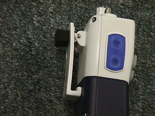
© 2001 PCTEST Lab UNIDEN FCC ID: AMWOVP2001610888 NVLAP Lab Code: 100431-0 150MHz Handheld VHF Radio © 2001 PCTEST Lab UNIDEN FCC ID: AMWOVP2001610888 NVLAP Lab Code: 100431-0 150MHz Handheld VHF Radio © 2001 PCTEST Lab UNIDEN FCC ID: AMWOVP2001610888 NVLAP Lab Code: 100431-0 150MHz Handheld VHF Radio © 2001 PCTEST Lab UNIDEN FCC ID: AMWOVP2001610888 NVLAP Lab Code: 100431-0 150MHz Handheld VHF Radio
ID Label/Location Info
© 2001 PCTEST Lab FCC ID SAMPLE LABEL & LOCATION LABELLING REQUIREMENTS PER §§ 2.925 & 15.19 The Label shown shall be permanently affixed at a conspicuous location on the device and be readily visible to the user at the time of purchase. (SEE NEXT PAGE)
Internal Photos
© 2001 PCTEST Lab UNIDEN FCC ID: AMWOVP2001610888 NVLAP Lab Code: 100431-0 150MHz Handheld VHF Radio © 2001 PCTEST Lab UNIDEN FCC ID: AMWOVP2001610888 NVLAP Lab Code: 100431-0 150MHz Handheld VHF Radio © 2001 PCTEST Lab UNIDEN FCC ID: AMWOVP2001610888 NVLAP Lab Code: 100431-0 150MHz Handheld VHF Radio
Internal Photos
© 2001 PCTEST Lab UNIDEN FCC ID: AMWOVP2001610888 NVLAP Lab Code: 100431-0 150MHz Handheld VHF Radio © 2001 PCTEST Lab UNIDEN FCC ID: AMWOVP2001610888 NVLAP Lab Code: 100431-0 150MHz Handheld VHF Radio © 2001 PCTEST Lab UNIDEN FCC ID: AMWOVP2001610888 NVLAP Lab Code: 100431-0 150MHz Handheld VHF Radio
Internal Photos
© 2001 PCTEST Lab UNIDEN FCC ID: AMWOVP2001610888 NVLAP Lab Code: 100431-0 150MHz Handheld VHF Radio © 2001 PCTEST Lab UNIDEN FCC ID: AMWOVP2001610888 NVLAP Lab Code: 100431-0 150MHz Handheld VHF Radio © 2001 PCTEST Lab UNIDEN FCC ID: AMWOVP2001610888 NVLAP Lab Code: 100431-0 150MHz Handheld VHF Radio
Operational Description
Test Report S/N: 80.210510298.AMW FCC Part 80 Dates of Tests: May 25-31, 2001 Type Acceptance © 2001 PCTEST Lab FCC ID: AMWOVP2001610888 1 2-Way Portable VHF Marine Radio Transceiver (GMDSS) MEASUREMENT REPORT 1.1 Scope Measurement and determination of electromagnetic emissions (EME) of radio frequency devices including intentional and/or unintentional radiators for compliance with the technical rules and regulations of the Federal Communications Commission. General Information Applicant Name: UNIDEN ENGINEERING SERVICES Address: 416 Maetan-3 Dong, Paldal-Ku Suwon City, Kyungki-Do, 441-742, KOREA Attention: Mr. Wallace Oh, Engineering Manager Samsung Electronics America (QA Lab) • FCC ID: AMWOVP2001610888 • Quantity: Quantity production is planned • Emission Designators: 16K0F3E • Tx Frequency Range: 156.025 ~ 157.425MHz • Rx Frequency Range: 156.050 ~ 163.275MHz • Max. Output Power: 5.0 W (HI) / 1.0 W (LOW) • FCC Classification(s): VHF Hand-held Transmitter - GMDSS (GHH) • Equipment (EUT) Type: 2-Way Portable VHF Marine Radio Transceiver (GMDSS) • Modulation(s): FM • Frequency Tolerance: ± 0.0005% (5.0 ppm) • FCC Rule Part(s): §§§ 80, 2.983, 2.987 • Dates of Tests: May 25-31, 2001 • Place of Tests: PCTEST Lab, Columbia, MD U.S.A. • Test Report S/N: 80.210510298.AMW Note: This device complies with the applicable general performance standards under § 80.1101(b), & the specific performance standards under § 80.1101(c)(2) of the FCC’s Rules and Regulations. Test Report S/N: 80.210510298.AMW FCC Part 80 Dates of Tests: May 25-31, 2001 Type Acceptance © 2001 PCTEST Lab FCC ID: AMWOVP2001610888 2 2-Way Portable VHF Marine Radio Transceiver (GMDSS) 2.1 INTRODUCTION These measurement tests were conducted at PCTEST Engineering Laboratory, Inc. facility in New Concept Business Park, Guilford Industrial Park, Columbia, Maryland. The site address is 6660-B Dobbin Road, Columbia, MD 21045. The test site is one of the highest points in the Columbia area with an elevation of 390 feet above mean sea level. The site coordinates are 39° 11'15" N latitude and 76° 49'38" W longitude. The facility is 1.5 miles North of the FCC laboratory, and the ambient signal and ambient signal strength are approximately equal to those of the FCC laboratory. There are no FM or TV transmitters within 15 miles of the site. The detailed description of the measurement facility was found to be in compliance with the requirements of § 2.948 according to ANSI C63.4 on October 19, 1992. Measurement Procedure The radiated and spurious measurements were made outdoors at a 3-meter test range (see Figure2). The equipment under testing was placed on a wooden turntable, 3-meters from the receive antenna. The receive antenna height and turntable rotations was adjusted for the highest reading on the receive spectrum analyzer. A half-wave dipole was substituted in place of the EUT. This dipole antenna was driven by a signal generator and the level of the signal generator was adjusted to obtain the same receive spectrum analyzer reading. This level was recorded. For readings above 1 GHZ, the above procedure would be repeated using horn antennas and the difference between the gain of the horn and an isotropic antenna are taken into consideration. Figure 1. Map of the Greater Baltimore and Metropolitan Washington, D.C. area. Figure 2. Diagram of 3-meter outdoor test range
RF Exposure Info
© 2001 PCTEST Engineering Lab., Inc. PCTEST Engineering Laboratory, Inc. 6660-B Dobbin Road • Columbia, MD 21045 • U.S.A. TEL (410) 290-6652 • FAX (410) 290-6654 http://www.pctestlab.com CERTIFICATE OF COMPLIANCE (SAR EVALUATION) UNIDEN ENGINEERING SERVICES Dates of Tests: May 21-22 & 31, 2001 216 John Street Test Report S/N: SAR.210510299.AMW P.O. Box 580 Test Site: PCTEST Lab, Columbia MD Lake City, SC 29560-0580 Attn: Mr. Jim Haynes, Vice President ~ Engineering & Regulatory Affairs FCC ID AMWOVP2001610888 APPLICANT UNIDEN ENGINEERING SERVICES EUT Type: Part 80 - VHF (Transceiver) Portable Marine Radio Tx Frequency: 156.025 ~ 157.425MHz Rx Frequency: 156.050 ~ 163.275MHz Max. Radiated Power: 5.0 Watts / 1.0 Watt Max. SAR Measurement: 0.906 mW/g (1g) 150MHz VHF MOUTH SAR 1.180 mW/g (1g) 150MHz VHF BODY SAR Trade Name/Model(s): UNIDEN /ATLANTIS & LTD925 FCC Classification: Licensed Non-Broadcast Transmitter Held to Face (TNF) Application Type: Certification Serial Number: n/a (pre production) FCC Rule Part(s): 2.1093; Part 80.1101 (c)(2) Modulation: FM This wireless portable device has been shown to be capable of compliance for localized specific absorption rate (SAR) for Controlled Environment/Occupational exposure limits specified in ANSI/IEEE Std. C95.1- 1992 and had been tested in accordance with the measurement procedures specified in ANSI/IEEE Std. C95.3-1992. (See Test Report). I attest to the accuracy of data. All measurements reported herein were performed by me or were made under my supervision and are correct to the best of my knowledge and belief. I assume full responsibility for the completeness of these measurements and vouch for the qualifications of all persons taking them. NVLAP accreditation does not constitute any product endorsement by NVLAP or any agency of the United States Government. PCTEST certifies that no party to this application has been denied the FCC benefits pursuant to Section 5301 of the Anti-Drug Abuse Act of 1988, 21 U.S.C. 862. 210510299.AMW Part 80 Certification SAR Measurement Report © 2001 PCTEST Engineering Lab., Inc. i Table of Contents 1.1 SCOPE 1 2.1 INTRODUCTION / SAR DEFINITION 2 3.1 SAR MEASUREMENT SET-UP 3 4.1 E-FIELD PROBE SYSTEM 4 5.1 E-FIELD PROBE CALIBRATION PROCESS 5 5.3 DATA EXTRAPOLATION 6 6.1 PHANTOM, HOLDER & EQUIVALENT TISSUES 7 7.1 SYSTEM SPECIFICATIONS 8 8.1 MEASUREMENT PROCESS 9 9.1 TEST POSITION OF THE RADIO 10 10.1 BODY-WORN CONFIGURATION 11 11.1 ANSI/IEEE C95.1 RF EXPOSURE LIMITS 12 12.1 MEASUREMENT UNCERTAINTIES 13 13.1 SAR TEST DATA SUMMARY 14-15 14.1 SAR TEST EQUIPMENT LIST 16 15.1 CONCLUSION 17 16.1 REFERENCES 18 APPENDIX A – SAR TEST PLOTS APPENDIX B – SAR TEST SETUP PHOTOGRAPHS APPENDIX C – DIPOLE VALIDATION DATA APPENDIX D – PROBE CALIBRATION DATA Test Report S/N: SAR.210510299.AMW SAR Measurement Report Test Dates: May 21-22, 2001 FCC Certification UNIDEN FCC ID: AMWOVP2001610888 © 2001 PCTEST Lab 150MHz Handheld VHF Radio 1 SAR MEASUREMENT REPORT 1.1 Scope Environmental evaluation measurements of specific absorption rate 1 (SAR) distributions in simulated human tissues exposed to radiofrequency (RF) radiation from wireless portable devices for compliance with the rules and regulations of the U.S. Federal Communications Commission (FCC). 2 Applicant Name: UNIDEN ENGINEERING SERVICES 216 John Street Address: P.O. Box 580 Lake City, SC 29560-0580 Attention: Mr. Jim Haynes, Vice President ~ Engineering & Regulatory Affairs • EUT Type: Part 80 - VHF (Transceiver) Portable Marine Radio • Trade Name: UNIDEN • Model(s): ATLANTIS & LTD925 • FCC IDENTIFIER: AMWOVP2001610888 • S/N: Pre-production • Tx Frequency: 156.025 ~ 157.425MHz • Rx Frequency: 156.050 ~ 163.275MHz • Application Type: Certification • FCC Classification: Licensed Non-Broadcast Transmitter Held to Face (TNF) • Modulation(s): FM • FCC Rule Part(s): § 2.1093; Part 80.1101 (c)(2) • Max. Radiated Power: 5.0 Watts / 1.0 Watt • Max. SAR Measurement: 0.906 mW/g (1g) 150MHz VHF MOUTH SAR 1.180 mW/g (1g) 150MHz VHF BODY SAR • Dates of Tests: May 21-22 & 31, 2001 • Place of Tests: PCTEST Engineering Lab. Columbia, MD, U.S.A. • Report Serial No.: SAR.210510299.AMW 1 Specific Absorption Rate (SAR) is a measure of the rate of energy absorption due to exposure to an RF transmitting source (wireless portable device). 2 IEEE/ANSI Std. C95.1-1992 limits are used to determine compliance with FCC ET Docket 93-62. Fig. 1 SAR Test Setup Test Report S/N: SAR.210510299.AMW SAR Measurement Report Test Dates: May 21-22, 2001 FCC Certification UNIDEN FCC ID: AMWOVP2001610888 © 2001 PCTEST Lab 150MHz Handheld VHF Radio 2 2.1 INTRODUCTION The FCC has adopted the guidelines for evaluating the environmental effects of radiofrequency radiation in ET Docket 93-62 on Aug. 6, 1996 to protect the public and workers from the potential hazards of RF emissions due to FCC-regulated portable devices.[1] The safety limits used for the environmental evaluation measurements are based on the criteria published by the American National Standards Institute (ANSI) for localized specific absorption rate (SAR) in IEEE/ANSI C95.1-1992 Standard for Safety Levels with Respect to Human Exposure to Radio Frequency Electromagnetic Fields, 3 kHz to 300 GHz. (c) 1992 by the Institute of Electrical and Electronics Engineers, Inc., New York, New York 10017.[2] The measurement procedure described in IEEE/ANSI C95.3-1992 Recommended Practice for the Measurement of Potentially Hazardous Electromagnetic Fields - RF and Microwave[3] is used for guidance in measuring SAR due to the RF radiation exposure from the Equipment Under Test (EUT). These criteria for SAR evaluation are similar to those recommended by the National Council on Radiation Protection and Measurements (NCRP) in Biological Effects and Exposure Criteria for Radiofrequency Electromagnetic Fields,” NCRP Report No. 86 (c) NCRP, 1986, Bethesda, MD 20814.[4] SAR is a measure of the rate of energy absorption due to exposure to an RF transmitting source. SAR val…
Text truncated - open the document above for the full version.
RF Exposure Info
Test Report S/N: SAR.210510299.AMW SAR Measurement Report Test Dates: May 21-22, 2001 FCC Certification UNIDEN FCC ID: AMWOVP2001610888 © 2001 PCTEST Lab 150MHz Handheld VHF Radio 14 13.1 SAR TEST DATA SUMMARY Ambient TEMPERATURE (°C) 20.9 Relative HUMIDITY (%) 58.2 Atmospheric PRESSURE (kPa) 99.3 Mixture Type: 150MHz Brain Dielectric Constant: 60.2 Conductivity: 0.48 S/m 13.2 Measurement Results (Mouth SAR) Frequency Modulation Power* Separation Distance Antenna Position SAR** MHz Ch. (Watts) (cm) (W/kg) 156.050 01 FM 4.96 2.5 cm Fixed 0.906 156.800 16 FM 5.01 2.5 cm Fixed 0.719 157.425 88 FM 4.99 2.5 cm Fixed 0.626 ANSI / IEEE C95.1 1992 - SAFETY LIMIT Spatial Peak (Muscle) Uncontrolled Exposure/General Population Mouth/Face 1.6 W/kg (mW/g) averaged over 1 gram NOTES: 1. All modes of operation were investigated and the worst-case are reported. 2. Battery condition is fully charged for all readings. 3. Battery ⌧ Standard Extended 4. *Power Measured Conducted EIRP ⌧ ERP 5. SAR Measurement System ⌧ SPEAG IDX 6. SAR Configuration ⌧ Mouth Body Hand Figure 15. MOUTH SAR Test Setup Test Report S/N: SAR.210510299.AMW SAR Measurement Report Test Dates: May 21-22, 2001 FCC Certification UNIDEN FCC ID: AMWOVP2001610888 © 2001 PCTEST Lab 150MHz Handheld VHF Radio 15 13.1 SAR TEST DATA SUMMARY Ambient TEMPERATURE (°C) 22.4 Relative HUMIDITY (%) 59.7 Atmospheric PRESSURE (kPa) 99.1 Mixture Type: 150 MHz Muscle Dielectric Constant: 62.7 Conductivity: 0.75 S/m 13.3 Measurement Results (Body SAR) Frequency Modulation Power* Separation Distance** Antenna Position SAR MHz Ch. (Watts) (cm) (W/kg) 156.050 01 FM 4.96 2.5 cm Fixed 1.050 156.800 16 FM 5.01 2.5 cm Fixed 1.150 157.425 88 FM 4.99 2.5 cm Fixed 1.180 ANSI / IEEE C95.1 1992 - SAFETY LIMIT Spatial Peak (Muscle) Uncontrolled Exposure/General Population Body 1.6 W/kg (mW/g) averaged over 1 gram NOTES: 1. All modes of operation were investigated and the worst-case are reported. 2. Battery condition is fully charged for all readings. 3. Battery ⌧ Standard Extended 4. *Power Measured Conducted EIRP ⌧ ERP 5. SAR Measurement System ⌧ SPEAG IDX 6. **SAR Configuration Mouth ⌧ Body Hand [Spacing distance measured = 2.5cm. The permanently attached carrying beltclip provides 1.3cm of this spacing. The additional 1.2cm is provided by the spacer contained in the optional speaker/microphone kit.] Figure 16. BODY SAR Test Setup Test Report S/N: SAR.210510299.AMW SAR Measurement Report Test Dates: May 21-22, 2001 FCC Certification UNIDEN FCC ID: AMWOVP2001610888 © 2001 PCTEST Lab 150MHz Handheld VHF Radio 16 14.1 SAR TEST EQUIPMENT 14.2 Type / Model Calib. Date S/N: Stäubli Robot RX60L Feb. 01 599131-01 Stäubli Robot Controller Feb. 01 PCT592 Stäubli Teach Pendant (Joystick) Feb. 01 3323-00161 Micron Computer Feb. 01 PCT577 450 MHz Pentium III, Windows NT SPEAG EDC3 Feb. 01 321 SPEAG DAE3 Feb. 01 330 SPEAG E-Field Probe ET3DV6 Feb. 01 1560 SPEAG Dummy Probe Feb. 01 PCT583 SPEAG Generic Twin Phantom Feb. 01 PCT587 SPEAG Light Alignment Sensor Feb. 01 205 SPEAG Validation Dipole D835V2 Feb. 01 PCT613 SPEAG Validation Dipole D1900V2 Feb. 01 PCT593 Brain Equivalent Matter (150MHz) May 01 PCTBEM17 Muscle Equivalent Matter (150MHz May 01 PCTBEM18 Brain Equivalent Matter (835MHz) May 01 PCTBEM13 Muscle Equivalent Matter (835MHz) May 01 PCTBEM15 Robot Table PCT586 Phone Holder PCT588 A/B Power Indicator PCT589 Remote Power Switch PCT590 Phantom Cover PCT591 HP Spectrum Analyzer Dec. 00 PCT200 IFI TEM Cell Model: CC110EXX Jan. 01 A427-0697 (DC - 2000 MHz) Microwave Amp. Model: 5S1G4 Jan. 01 22332 (800MHz - 4.2GHz, 5 Watts) NOTE: The E-field probe was calibrated by SPEAG. The SAR calibration of the E-field probe is performed by temperature measurement procedure. A TEM cell is used for the free space calibration of the probe. The tissue simulating material is calibrated by PCTEST using the dielectric probe system and network analyzer to determine the conductivity and permittivity (dielectric constant) of the desired equivalent material. The following list of equipment was used to calibrate the equivalent materials: Power Meter Gigatronics 8651A Signal Generator HP-8648D (9kHz ~ 4GHz) Power Amp Amplifier Research 5S1G4 (5 Watts, 800MHz ~ 4.2GHz) Network Analyzer HP-8753E (30kHz ~ 3GHz) Dielectric Probe Kit HP85070B Test Report S/N: SAR.210510299.AMW SAR Measurement Report Test Dates: May 21-22, 2001 FCC Certification UNIDEN FCC ID: AMWOVP2001610888 © 2001 PCTEST Lab 150MHz Handheld VHF Radio 17 15.1 CONCLUSION The SAR measurement indicates that the EUT complies with the RF radiation exposure limits of the FCC. These measurements are taken to simulate the RF effects exposure under worst-case conditions. Precise laboratory measures were taken to assure repeatability of the tests. Please note that the absorption and distribution of electromagnetic energy in the body are very complex phenomena that depend on the mass, shape, and size of the body, the orientation of the body with respect to the field vectors, and the electrical properties of both the body and the environment. Other variables that may play a substantial role in possible biological effects are those that characterize the environment (e.g. ambient temperature, air velocity, relative humidity, and body insulation) and those that characterize the individual (e.g. age, gender, activity level, debilitation, or disease). Because innumerable factors may interact to determine the specific biological outcome of an exposure to electromagnetic fields, any protection guide shall consider maximal amplification of biological effects as a result of field-body interactions, environmental conditions, and physiological variables.[3] Test Report S/N: SAR.210510299.AMW SAR Measurement Report Test Dates: May 21-22, 2001 FCC Certification UNIDEN FCC ID: AMWOVP2001610888 © 2001 PCTEST Lab 150MHz Handheld VHF Radio 18 16.1 REFERENCES: [1] Federal Communications Commission, ET Docket 93-62, Guidelines for Evaluating th…
Text truncated - open the document above for the full version.
RF Exposure Info
© 2001 PCTEST Lab UNIDEN FCC ID: AMWOVP2001610888 NVLAP Lab Code: 100431-0 150MHz Handheld VHF Radio © 2001 PCTEST Lab UNIDEN FCC ID: AMWOVP2001610888 NVLAP Lab Code: 100431-0 150MHz Handheld VHF Radio © 2001 PCTEST Lab UNIDEN FCC ID: AMWOVP2001610888 NVLAP Lab Code: 100431-0 150MHz Handheld VHF Radio © 2001 PCTEST Lab UNIDEN FCC ID: AMWOVP2001610888 NVLAP Lab Code: 100431-0 150MHz Handheld VHF Radio Test Report S/N: SAR.210510299.AMW SAR Measurement Report Test Dates: May 21-22, 2001 FCC Certification UNIDEN FCC ID: AMWOVP2001610888 © 2001 PCTEST Lab 150MHz Handheld VHF Radio APPENDIX C — DIPOLE VALIDATION DATA 835MHz Brain Dipole Validation Generic Twin Phantom; Flat Section; Probe: ET3DV6 - SN1560 -- Probe Cal Date 20/02/01 Med. Parameters 835 MHz Brain: σ = 0.86 mho/m ε r = 42.5 ρ = 1.00 g…
Text truncated - open the document above for the full version.
Contact Information
Applicant
Paul Roby
Test Firm
PCTEST Engineering Laboratory, Inc.Randy Ortanez
Technical Specifications
| # | Rule Parts | Frequency Range | Power Output | Emission | Tolerance |
|---|---|---|---|---|---|
| 2 | 8 | 156.025 MHz - 157.425 MHz | 1 W | 16K0F3E | 0.0005 % |
Other Applications from Uniden America Corporation
AMWUA2405
Apr 15, 2026RADAR DETECTOR
Equipment Class
JBP - Part 15 Class B Computing Device PeripheralAMWUA2406
Apr 15, 2026RADAR DETECTOR
Equipment Class
JBP - Part 15 Class B Computing Device PeripheralAMWUA2402
Jul 23, 2024RADAR DETECTOR
Equipment Class
CRD - Part 15 Radar Detector
AMWUA2404
Feb 17, 2024Wi-Fi Bluetooth Combo Module
Equipment Class
DTS - Digital Transmission System
AMWUA2301
Feb 15, 2023RADAR DETECTOR
Equipment Class
CRD - Part 15 Radar Detector