AMWUB305CTrunk Tracker Scanner
Uniden America Corporation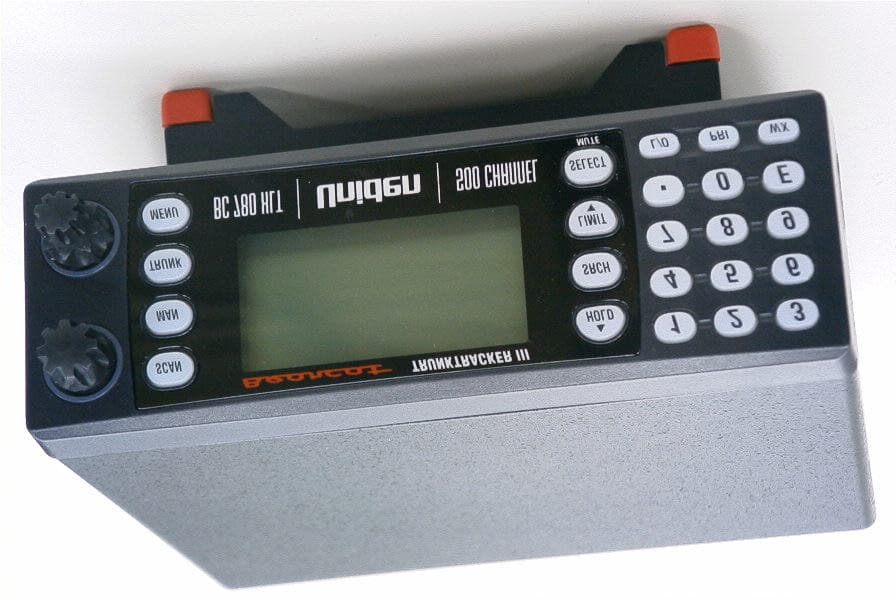
Click to zoom
Application Details
- Equipment Class
- CSR - Scanning Receiver
- Date of Grant
- Jan 13, 2002
- Application Purpose
- Original Equipment
- Date of Application
- Nov 28, 2001
- Equipment Note
- Trunk Tracker Scanner
- Frequency Range
- 1240.00000000 - 1300.00000000
- Company
- Uniden America Corporation
- Country
- United States
Documents & Files
Document Text
Text extracted from the exhibit documents filed with the FCC. Open a document above to read the original.
Users Manual
500-Channel Trunk Tracking Scanner Visit our Website at www.bc780xlt.com BC780XLT TRUNK TRACKER III bc780xlt foldouts.qxd 10/08/2000 4:50 PM Page 1 BandFrequency RangeModeStep No.(MHz)(kHz) 22470.0000–472.9875NFM12.5 473.0000–475.9875NFM12.5 476.0000–478.9875NFM12.5 479.0000–481.9875NFM12.5 482.0000–484.9875NFM12.5 485.0000–487.9875NFM12.5 488.0000–490.9875NFM12.5 491.0000–493.9875NFM12.5 494.0000–496.9875NFM12.5 497.0000–499.9875NFM12.5 500.0000–502.9875NFM12.5 503.0000–505.9875NFM12.5 506.0000–508.9875NFM12.5 509.0000–511.9875NFM12.5 (470.0000)–512.0000NFM12.5 23806.0000–823.9875NFM12.5 849.0125–850.9875NFM12.5 851.0000–868.9875NFM12.5 894.0125–895.9875NFM12.5 896.0000–901.0000NFM12.5 901.0125–934.9875NFM12.5 935.0000–940.0000NFM12.5 940.0125–956.0000NFM12.5 241240.0000–1300.0000NFM12.5 BandFrequency RangeModeStep No.(MHz)(kHz) 125.0000–26.9600AM5 226.9650–27.4050AM5 327.4100–27.9950AM5 428.0000–29.6900FM10 529.7000–49.9900FM10 650.0000–53.9900FM10 754.0000–71.9500WFM50 872.0000–75.9950FM5 976.0000–87.9500WFM50 1088.0000–107.9000WFM100 11108.0000–136.9750AM25 12137.0000–143.9950FM5 13144.0000–147.9950FM5 14 148.0000–161.9950FM5 162.0000–173.9875FM12.5 15174.0000–215.9500WFM50 16216.0000–224.9950FM5 17225.0000–399.9500AM50 18400.0000–405.9875NFM12.5 19406.0000–419.9875NFM12.5 20420.0000–424.9875NFM12.5 425.0000–429.9875NFM12.5 430.0000–449.9875NFM12.5 21450.0000–454.9875NFM12.5 455.0000–459.9875NFM12.5 460.0000–464.9875NFM12.5 465.0000–469.9875NFM12.5 Introduction The BC780XLT is a state-of-the-art radio with TrunkTracking™ and automatic scanning capabilities. It can store frequencies such as police, fire/emergency, marine, railroad, air, amateur, and other communications into 10 banks of 50 channels each. With the new SmartScanner™ feature, you can also automatically program your scanner by downloading directly from our Uniden/Bearcat national frequency database via a PC or external modem. Use your new scanner to monitor: • Police and Fire Departments (including rescue and paramedics) • VHF High Band, UHF, 800/900MHz Trunked Public Safety Systems • Trunking for Motorola, EDACS and LTR Systems • NOAA Weather Broadcasts • Business/Industrial Radio • Utilities • Marine and Amateur (ham radio) Bands • Air Band • And much more... The chart below identifies the scanner band numbers, the frequency range, the modulation mode and the default step size settings. bc780xlt foldouts.qxd 10/08/2000 4:50 PM Page 2 Front View and Display 1. VFO/SELECT Control 2. VOLUME/SQUELCH Control 3. Scan Key ( SCAN) 4. Manual Key ( MAN) 5. Display 6. Search Key ( SRCH) 7. Hold/Up Key ( HOLD/s) 8. Numeric Keypad (each banks channel numbers) 9. Menu Key ( MENU) 10. Trunk Key ( TRUNK) 11. Limit/Down Key ( LIMIT/t) 12. Select/Mute Key ( SELECT/MUTE) 13. Decimal/Reverse Key ( /RVRS) 14. Lockout Key ( L/O) 15. Priority Key ( PRI) 16. Weather Key ( WX) 17. Enter/Remote Key (E/REM) 18. Trunk Mode Indicator 19. Trunk Type Indicators 20. Frequency Display 21. Priority Channel Indicator 22. Channel Number Display 23. Bank/Trunk Scan List Indicator 24. Scanner/Channel Mode Indicators 25. Receiving Mode Indicators 26. Frequency/Channel Indicators 27. CTCSS/DCS Indicators 28. ID/Code/Frequency Display 29. Trunk Repeater Activity Indicators 30. Enter Lock Indicator 31. Signal Meter 32. Character Display 1 18 19 20 32 2122232425 262728 30 31 345678 9 1011121314151617 2 29 bc780xlt foldouts.qxd 10/08/2000 4:50 PM Page 3 Rear View 33. Antenna Connector 34. Tape Recorder Output Jack Uniden ® and Bearcat ® are registered trademarks of Uniden America Corporation. TrunkTrack and SmartScanner are proprietary trademarks of Uniden America Corporation. 35. External Speaker Jack 36. DC Power Jack 37. Remote Control Terminal 3334353637 bc780xlt foldouts.qxd 10/08/2000 4:50 PM Page 4 This shortcut card is designed to assist you in getting through the menu screens using the direct entry mode for commonly used features. Please read the manual thoroughly before using this card. Be sure to back out of the menu screen after each shortcut by repeatedly pressing MENU. bc780xlt foldouts.qxd 10/11/2000 10:37 AM Page 11 If you need any assistance with this product, please call our Customer Service Hotline at 1-800-297-1023. A Uniden representative will be happy to help you with any matters regarding the operation of this unit, available accessories, or any other related matters. Hours: M-F 7:00 a.m. to 7:00 p.m., Central time. Also please check out our website at www.uniden.com bc780xlt foldouts.qxd 10/11/2000 10:37 AM Page 6 i Contents Introduction . . . . . . . . . . . . . . . . . . . . . . . . . . . . . . . . . . . . . . . . . . . . . . . . . . . . . . . . .inside front cover Important Notice . . . . . . . . . . . . . . . . . . . . . . . . . . . . . . . . . . . . . . . . . . . . . . . . . . . . . . . . . . . . . . . . .1 Terminology . . . . . . . . . . . . . . . . . . . . . . . . . . . . . . . . . . . . . . . . . . . . . . . . . . . . . . . . . . . . . . . . . . . . .2 What is Scanning? . . . . . . . . . . . . . . . . . . . . . . . . . . . . . . . . . . . . . . . . . . . . . . . . . . . . . . . . . . . . . .2 What is Searching? . . . . . . . . . . . . . . . . . . . . . . . . . . . . . . . . . . . . . . . . . . . . . . . . . . . . . . . . . . . . .2 What is Trunk Tracking? . . . . . . . . . . . . . . . . . . . . . . . . . . . . . . . . . . . . . . . . . . . . . . . . . . . . . . . . . .2 Feature Highlights . . . . . . . . . . . . . . . . . . . . . . . . . . . . . . . . . . . . . . . . . . . . . . . . . . . . . . . . . . . . . . . .4 Where to Obtain More Information . . . . . . . . . . . . . . . . . . . . . . . . . . . . . . . . . . . . . . . . . . . . . . . . . . . .5 Information on the Internet . . . . . . . . . . . . . . . . . . . . . . . . . . . . . . . . . . . . . . . . . . . . . . . . . . . . . . . .5 Included with Your Scanner . . . . . . . . . . . . . . . . . . . . . . . . . . . . . . . . . . . . . . . . . . . . . . . . . . . . . . . . .6 Set…
Text truncated - open the document above for the full version.
Users Manual
7 Setup Connecting an Antenna You must install an antenna before you can operate the scanner. You have been provided a standard telescopic antenna that works well with this scanner, but you may want to purchases another type to increase the range. To connect the telescopic antenna, simply connect it to the BNC type ANT. connector on the rear of the scanner. You can purchase a variety of scanner antennas for both mobile and base station available at a local electronics store. Choose the one that best meets your needs. When deciding on a mobile or base station antenna and its location, consider these points. • The antenna should be as high as possible on a vehicle or a house. • The antenna and its cable should be as far as possible from sources of electrical noise (ignition systems, gauges, and so on). • The antenna should be vertical for the best performance. Mounting an Antenna Once you choose an antenna, follow the mounting instructions supplied with the antenna. Then route the antenna cable to the scanner. The antenna connector on your scanner makes it easy to use the scanner with a variety of antennas, such as an external mobile antenna or an outdoor base station antenna. Always use 50 ohm coaxial cable, such as RG-58 or RG-8, to connect an outdoor antenna. For lengths over 50 feet, use RG-8 low-loss dielectric coaxial cable. If your antenna’s cable does not have a BNC connector, you will also need a BNC adapter (available at a local electronics store). Follow the Installation instructions supplied with the antenna, route the antenna cable to the scanner, then connect it to the ANT.jack. Warning: Use extreme caution when you install or remove an outdoor antenna. If the antenna starts to fall, let it go! It could contact overhead power lines. If the antenna touches a power line, contact with the antenna, mast, cable, or guy wires can cause electrocution and death. Call the power company to remove the antenna. DO NOT attempt to do it yourself. Optional Antenna If you have chosen an optional mobile antenna, connect the antenna plug into the ANT connector on the rear of the scanner. (For more information on antenna installation, please refer to the instruction guide that came with your antenna.) BC780XLT1.qxd 10/08/2000 5:02 PM Page 7 8 Typical Mounting Methods The BC780XLT can be conveniently mounted on a table, bulkhead, overhead, or any other desired location (refer to figure below for typical mounting methods). Caution: Make sure there are no hidden electrical wires or other items behind the desired location before proceeding. Check that free access for mounting and cabling is available. Mounting the Scanner in Your Vehicle Before you mount the scanner, make sure you have all the necessary materials. Then confirm that the scanner fits your vehicle’s mounting area. This unit requires a mounting area of 2-3/8 inch high by 6-15/16 inch wide by 6 -9/16 inch deep (61 x 176.5 x 167 mm). Caution: Be sure to avoid obstructions behind the mounting surface. Follow these steps to mount the scanner in your vehicle. 1. Choose a mounting location, then use the supplied mounting bracket as a template to mark the positions for the mounting screw holes. 2. In the marked positions, drill holes slightly smaller than the supplied screws. 3. Attach the mounting bracket to the mounting location using the supplied screws and lock washers. 4. Attach the scanner to the mounting bracket using the supplied mounting knobs. 5. Connect the antenna’s cable to theANT. connector on the back of the scanner. Note: If the antenna cable’s connector does not fit in the ANT. connector, you might also need a Motorola-to-BNC antenna plug adapter (available at a local electronics store). • Table top mount• Bulkhead mount• Overhead mount BC780XLT1.qxd 10/08/2000 5:02 PM Page 8 9 Applying Power for Vehicle Installation You can power your scanner using either the supplied DC power cord or your vehicle’s cigarette lighter socket using DC cigarette lighter power cord. Caution: You must use a power source that supplies 13.8 V DC and delivers at least 700 mA. Your standard 12V car battery should be sufficient. The cord connector’s center tip must be set to positive and its plug must fit the scanner’s DC 13.8 V jack. The supplied DC power cord meets these specifications. Using a power cord that does not meet these specifications could damage the scanner or the adapter. • Always connect the adapter or DC power cord to the scanner before you connect it to the power source. When you finish, disconnect the adapter or DC power cord from the power source before you disconnect it from the scanner. • For added safety and to protect your scanner, disconnect the cable from your vehicle battery’s negative (-) terminal before you begin. Follow these steps to connect the supplied DC power cord. 1. Connect the power cord’s black wire to a chassis ground, such as a metal screw attached to a metal part of the vehicle’s frame. Be sure that the screw is not insulated from the frame by a plastic part. 2. Connect the power cord’s red wire (with in-line fuse) to a source of voltage that turns on and off with the ignition switch, such as a spare accessory terminal in your vehicle’s fuse box. 3. Insert the power cord’s barrel plug into the DC 13.8 V jack on the back of the scanner. 4. Reconnect the cable to the vehicle battery’s negative (-) terminal. To power the scanner from a vehicle’s 12 V power source (such as a cigarette-lighter socket), use the supplied cigarette-lighter adapter cord. To connect the supplied DC cigarette-lighter power cord, insert its barrel plug into the DC 13.8 Vjack on the back of the scanner, then plug the power cord into your vehicle’s cigarette lighter socket. Note: If you use a cigarette-lighter power cord and your vehicle’s engine is running, you might hear electrical noise from the engine while scanning. This is normal. BC780XLT1.qxd 10/08/2000 5:02 PM Page 9 10 Desktop Installation You can place this scanner on a desk, she…
Text truncated - open the document above for the full version.
Users Manual
20 Before the BC780XLT can begin conventional scanning, you must program a frequency into at least one channel. Repeat this procedure for each channel you want to program. Storing Frequencies into Channels 1. Select frequencies from your dealer, from various sources on the internet, or from one of the guides listed on page 5. Here is a list of sample frequencies you should try: 156.800 Marine Calling channel 155.340 Ambulance operations 155.280 Ambulance operations 155.160 Ambulance operations 462.950 Ambulance operations 462.5625 Family Radio Services (channel one) 2. Press MAN. 3. Select a channel. a. Enter the channel number. b. Then press MAN. 4. Enter the frequency. a. Enter the frequency number. b. Then press E. Note: • To clear a mistake while entering the frequency, press (decimal key) repeatedly until the display is cleared. • If you enter a channel or frequency which is out of the scanner’s range, a distinctive beep will sound and ERRORappears in the display. • You can use sor twhen selecting a channel. Press and hold sor tfor 1 second to move up/down more quickly. Programming BC780XLT1.qxd 10/08/2000 5:02 PM Page 20 21 Duplicate Frequency Alert If you enter a frequency which has been stored in another channel, you will hear a beep and the other channel displays WARNING. Press to clear and start again. ––– OR ––– Press Eagain to store the frequency in both channels. Storing Text Tags You can customize your scanner by storing text tags for easy identification of banks, channel transmissions, trunking talkgroup IDs, etc. The text tags can be set at the menu mode. (Refer to Understanding Menu System on page 13.) Assigning a Bank Tag to a Bank 1. Press MENU. 2. Press E to select SYSTEM DATA. 3. Press s or t to select BANK TAGand then press E. 4. Select the bank number to be tagged using sor t and then press E. 5. The cursor appears on the display. Rotate VFOto change letters, and then press sor tto shift right or left. Both capital and lower case letters are available, as well as numbers and punctuation marks. 6. After entering the desired text, press E or SELECT. + Remember!You can also use the VFOcontrol for scrolling. To clear a mistake while entering the frequency, press (decimal key) repeatedly until the display is cleared. Assigning a Text Tag to a Channel 1. Press MENU. 2. Press s or t to select C H DATAand then press E. 3. Select the channel number to be tagged using sor tand pressing E. You can also enter the channel number in using the keypad and then press E. 4. Press s or tto select ALPHA TAGand then pressing E. Note: • If you have not stored a frequency in the channel, UNREGISTEREDwill appear in the display. 5. The cursor appears on the display. Rotate VFOto change letters, and press sor tto shift right or left. Both capital and lower case letters are available, as well as numbers and punctuation marks. 6. After entering the desired text, press E,SELECTor VFO. BC780XLT1.qxd 10/08/2000 5:02 PM Page 21 22 Beep Alert The scanner can alert you with three rapid beeps at the beginning of a transmission on an assigned frequency. Assigning the beep alert to a channel This alert can be set on/off to every channel (or to every ID memory for Trunking mode). 1. Press MENU. 2. Press s or t to select C H DATAand then press E. 3. Select the channel number to be tagged using sor tand then press E. (You can also enter the channel number in using the keypad or VFOcontrol and then press E.) 4. Press s or tto select BEEP ALERTand then press E. 5. Press s or tto select ON orOFFand then pressing E. Note: If NOT REGISTERappears, make sure a frequency is stored in the channel. Programming Tips • Do not program a weather frequency into one of the channels, since weather channels transmit continuously. Use the Weather Search feature to select the weather information band. • Group similar services into a bank. For example, program police frequencies in channels 1 through 10 and fire/emergency into channels 51 through 60, and so on. • Put the frequency that you listen to the most or the most important frequency into a Priority channel. • To quickly program a series of channels, start with the lowest number channel. For example, when you are programming five new frequencies into Channels 4 through 8, start with Channel 4. After you finish programming a channel, press MANor HOLD/s to go to the next higher channel. • Write down your programmed channels and frequencies and put in a convenient place in case of accidental reprogramming. • If you want to download frequencies using the SmartScan feature, go to page 59 in this manual. • Frequencies are rounded off according to the step of each channel. • When you are overwriting a tagged channel with a new frequency, the previous alpha tag will be deleted. You must re-enter the alpha tag. • When programming frequencies, a 2 second delay is set automatically but can be changed in the Channel Data menu. Deleting a Stored Frequency To delete a stored frequency: a. Select a channel. b. Press 0. c. Then press E. Note: Channels with no frequencies are automatically locked out. SERVICE SEARCH PUBLIC SAFETY BC780XLT1.qxd 10/08/2000 5:02 PM Page 22 23 1. After programming frequencies, simply press SCANto begin scanning. 2. The bank indicators selected for scanning appear in the display, and the bank being currently monitored flashes. You can deselect banks from active scanning by pressing their number on your keypad. The indicator for each deselected bank turns off, and the banks channels are not scanned. Note: One Bank must always be active. You cannot deactivate all ten banks at the same time. If you try to turn off all the banks, the first bank is automatically selected. To restore a bank to active scanning, press the banks number on your keypad. The banks indicator will display again. 3. During normal scanning the scanner skips unprogrammed or locked out channels. 4. When a transmission is received, the scanner stops on that channel. When the transmission ends…
Text truncated - open the document above for the full version.
Users Manual
33 The Service Search feature allows you to toggle through the following ten preprogrammed services. The frequencies selected for these services are the most commonly used around the U.S. • 1: PUBLIC SAFETY• 6: RAILROAD • 2: NEWS• 7: AIR • 3: TV BROADCAST• 8: CB RADIO • 4: HAM RADIO• 9: FRS • 5: MARINE• 0: SPECIAL(frequencies) 1. Press SRCHfor 2 seconds. the display indicates as illustrated. 2. After a 3 second delay, searching begins for the first preprogrammed service – Public Safety (initial setting). 3. If you want to skip a frequency, press SRCHto start searching immediately. 4. To change the searched service, use s, tor VFOafter pressing SRCHfor 2 seconds. Note: • You can not change such settings as delay, during a service search. • The channel number corresponding to certain services will appear when a frequency within the search is active. • You can enter one of the Service Search frequencies into Channel Memory by pressing Ewhen holding on one of the frequencies. • Special Frequencies are low-power, itinerant, FRS, "splinters" and other frequencies which are commonly used at special events and other locations and may or may not be licensed. 5. To exit from the service search mode, press MANor SCAN. During the search of one of the preprogrammed services, the lower display line will indicate the service that you are searching. To stop the search, press HOLD/s.HOLDappears in the display. Press HOLD/sor LIMIT/tto move up or down one programmed frequency, or press SRCHto resume scanning. Service Search Skip You can set the scanner to skip the frequencies unwanted during service search. 100 skipped frequencies are programmable. 1. To skip over a frequency, press L/Owhen stopping at the frequency you want to skip. 2. To cancel a skip during search, press HOLD/s, tune in the desired frequency using s, tor VFO, then press L/O. To restore all skipped frequencies, press L/O for 2 seconds. Service Search BC780XLT1.qxd 10/08/2000 5:02 PM Page 33 34 Weather Channel Search To hear preprogrammed NOAA weather channels: 1. Press WX. Note: • It’s possible to receive more than one weather broadcast in your area. If the broadcast sounds weak or distant, press SRCHto look for a closer station. • Press HOLD/sif you want to stop searching (WX hold mode). NWR-SAME Alert In addition to the conventional weather broadcasts, your BC780XLT is compatible with NWR-SAME weather alert. When the scanner receives NOAA’s Specific Area Message Encoding (SAME) coded weather emergency signal, it sounds the alert tone with specified message. You must program your FIPS code to identify the Specific Area where you are located. 1. While receiving a weather channel or at the WX hold mode, press WXto activate this feature. The ALT icon displays.The audio is muted but the scanner is still actively waiting to detect the coded SAME emergency warning signals. 2. When the unit receives a warning signal, it shows a message with the alert tone defined. (For NWR- SAME Event Code, see the table in the Appendix.) 3. To deactivate, just press WXor it is automatically canceled when the channel is changed. Testing the Alert Siren To test and recognize the difference between the types of alert sirens, perform the following steps: 1. During WX hold mode, press and hold the PRIkey until you hear the Statement Alert siren. ALTappears on the display and the Statement, watch, warning sirens sound alternately. Note: The samples of the each alert siren only last for a few seconds. You may need to listen to each siren several times to be sure you recognize the different sirens and tones. The sirens continue to sound rotating through the samples until you silence the test. 2. To stop the test, press any key. Make sure you can hear the siren in all areas that you would need to. If not, optional accessories can be purchased to ensure that you are alerted for emergency broadcasts. See your dealer or local electronics store for accessories. DO NOT USE THE EARPHONE TO LISTEN TO THE TEST. DAMAGE TO YOUR HEARING COULD OCCUR. BC780XLT1.qxd 10/11/2000 10:39 AM Page 34 35 Programming FIPS Code The 6-digit Federal Information Processing System (FIPS) codes established by the National Weather Service (NWS) must be programmed in your scanner. These codes specify an emergency and the specific geographic area (such as county) affected by the emergency. 1. At the WX hold mode, press and hold WXfor 2 seconds. 2. Select the desired memory number (F1-F15) using sor t. 3. Enter FIPS code using the keypad. 4. Press E. 5. To exit from this programming mode, press WX. ––– OR ––– 1. Press twhen F1 is displayed or swhen F15 is displayed. 2. Press E. The scanner is now set for ALL FIPS mode. 3. To cancel this ALL FIPS mode, enter individual FIPS code again. Note: • To cancel the entry, press . • To obtain the FIPS code for your area, contact the NWS toll free at 1-888-697-7263.(1-888-NWR-SAME) or visit their website http://www.nws.noaa.gov/nwr/indexnw.htm BC780XLT1.qxd 10/08/2000 5:02 PM Page 35 36 Trunked Systems Your BC780XLT is designed to track three major types of trunked radio systems. These systems are described here. vMOTOROLA - Including Type I, Type II, Hybrid, SMARTNET, and Privacy Plus. Motorola systems are widely used by public safety and business users. Most are on the 800 MHz band, and recent systems are appearing on other bands. vEDACS - Including "Wideband" 9600 baud, and "Narrowband" 4800 baud systems. "Wideband" systems are mostly on the 800 MHz band, and are used by public safety, utilities, and business users. Some systems are used on the VHF and UHF bands. "Narrowband" systems are used in the 935-940 MHz band, many by utilities. (See page 49) vLTR - These systems are mostly for business users, and found on the UHF, 800 and 900 MHz bands. (See page 52) For details on the operation and programming for all of these systems, see pages 36-58. When tracking these types of systems, remember these important points: • Your scanner defaults to monitor Motorola…
Text truncated - open the document above for the full version.
Users Manual
49 EDACS ® Reception EDACS ® Tracking TrunkTracker III now allows tracking of EDACS ® trunked systems. Until now these widely used systems have been almost impossible to monitor with a conventional scanner. With your TrunkTracker III listening to EDACS(s) is remarkably easy, and perhaps even easier than conventional scanning. EDACS systems use 'Transmission Trunking', which means that each transmission is assigned a new frequency. As the conversation moves through the system's frequencies, your TrunkTracker II automatically follows it. This chart shows a 30 second sample of EDACS transmissions. Eight different talkgroups are using the system as their transmissions switch between the thirteen system frequencies. Notice how the dotted line shows talkgroup 02-023 moving from channel to channel. Your BC780XLT can clearly and automatically follow this talkgroup, or any other, as you select. EDACS systems are organized in a logical way that keeps related talkgroups together. Your scanner is designed to take maximum advantage of this organization to make your scanning easy. It lets you zero in on just the part of the system you want to hear, whether it is an individual channel or an entire department or city. Programming EDACS System Frequencies When you program EDACS frequencies, it is critical that you store each one in the CORRECT LOCATION. By the nature of EDACS systems this is necessary for tracking. This often is not the frequency order, so you must be sure you have the right sequence. Sources for this information includewww.trunktracker.comand www.bc780xlt.com. BC780XLT1.qxd 10/08/2000 5:02 PM Page 49 50 An EDACS ® Trunked system This chart shows how talkgroups are organized within an EDACS system at the AGENCY level. The individual talkgroups cannot be shown at this scale because there are over 2000. However the chart can show the 16 Agencies in this example. The system is logical and easy to understand. EDACS systems are typically arranged in an outline structure. The system users are given blocks of talkgroups. Sizes vary but most large cities and other agencies have blocks of 128 channels. Smaller cities have only 64 or 32 channels. In this example, the County Sheriff is agency 01. The city of Sullivan is Agency 03. Adams Hill and Matthew Junction share Agency 08. Your scanner shows EDACS talkgroups in AFS (Agency-Fleet-Subfleet) format. This helps you see, at a glance, who you are monitoring. And with the partial-entry feature you can easily include nearby, related channels in the same Fleet or Agency. You can just as easily exclude entire unwanted Fleets and Agencies. When in Search mode, with the system frequencies programmed, and your scanner locked to the control channel, you can select a desired city by keying in the AGENCY part of the AFS talkgroup. For example, you can select the entire city of Sullivan with 4 key presses zero, three, , SRCH. When you hear an interesting talkgroup, capture it to your scan list by pressing Eduring the transmission. Or HOLD on it by pressing the HOLDkey. If you want to monitor the Sullivan Police Dispatch channel (which is talk group 03-062), press zero, three, , zero, six, two, HOLD. Your scanner can also work in DECIMAL format. This talkgroup in decimal format is 434. But decimal format does not give you any information about the system hierarchy. For example Sullivan, in decimal, uses channels from 384 to 511. This is not as easy to remember as Agency 03. But decimal is useful if you need to work from decimal talkgroup lists. BC780XLT1.qxd 10/08/2000 5:02 PM Page 50 51 Special EDACS ® Features AFS Partial Entry Feature AFS is Uniden's method of encoding EDACS talkgroups. AFS stands for 'Agency-Fleet-Subfleet'. AFS talkgroups are used in all EDACS reception -- in ID SEARCH, ID LOCKOUT and ID SCAN scanlists. The powerful AFS Partial Entry feature designed into the BC780XLT lets you use either a complete talkgroup code, or just the most significant part. This feature lets you expand or narrow searching and scanning to one of 4 levels. By entering only the desired part of an AFS talkgroup, you can select 2048 talkgroups, 128 talkgroups, 8 talkgroups, or a single talkgroup. For example, you could program every talkgroup in a police department with just 4 key presses. You can use the AFS Partial Entry feature anywhere that you need to specify EDACS talkgroup. Your BC780XLT can also enter or display EDACS talkgroups in decimal format (0-2047). Press MENU - TRUNK DATA, and for banks selected as EDACS banks, select Item 8, EDACS ID FORM and change it to Decimal. You can use this feature to translate decimal talkgroups lists to the much more powerful AFS format. Examples of how you might use AFS are shown above in the description of an EDACS trunked system, and elsewhere in this manual. It is very easy to use. Be sure to become familiar with AFS Partial Entry, and your scanning will become far more flexible and efficient. Emergency Call Alert Your BC780 alerts you when an EDACS Emergency transmission occurs. EDACS systems often provide users with an 'Emergency' button on their radios. Users in trouble can alert the dispatcher and other units and get priority access to the radio system. When a user activates Emergency mode your scanner will flash EMERGENCY during the entire transmission. At the beginning of each transmission it will sound a distinctive emergency alert tone three times. Patch Tracking The BC780 can follow EDACS patched talkgroups. EDACS systems sometimes bring several talkgroups together in a 'Patch'. A patch might be used by a police agency at night to provide a single channel with a single dispatcher for a wide area. A patch is created when a single, temporary talkgroup substitutes for the original talkgroups. While the patch is running, which may be for hours or days, the original talkgroups cease to be used. If you were monitoring one of these talkgroups, you might think there was no traffic, but in fact the talkgroup was operating …
Text truncated - open the document above for the full version.
Contact Information
Applicant
Paul Roby
Test Firm
Uniden CorporationKeizo Fujiwara
81-3-5543-2875
Technical Specifications
| # | Rule Parts | Frequency Range | Power Output |
|---|---|---|---|
| 6 | 15B | 1.24 GHz - 1.30 GHz | - |
Other Applications from Uniden America Corporation
AMWUA2405
Apr 15, 2026RADAR DETECTOR
Equipment Class
JBP - Part 15 Class B Computing Device PeripheralAMWUA2406
Apr 15, 2026RADAR DETECTOR
Equipment Class
JBP - Part 15 Class B Computing Device PeripheralAMWUA2402
Jul 23, 2024RADAR DETECTOR
Equipment Class
CRD - Part 15 Radar Detector
AMWUA2404
Feb 17, 2024Wi-Fi Bluetooth Combo Module
Equipment Class
DTS - Digital Transmission System
AMWUA2301
Feb 15, 2023RADAR DETECTOR
Equipment Class
CRD - Part 15 Radar Detector