AMWUB330Portable Scanner
Uniden America Corporation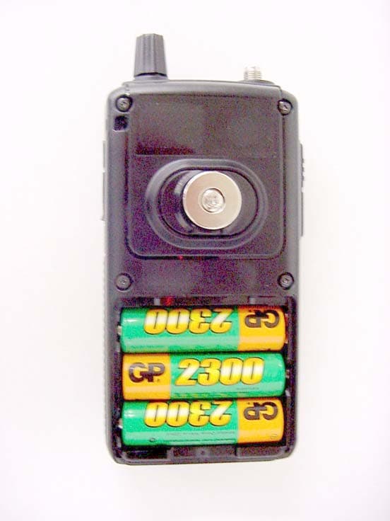
Click to zoom
Application Details
- Equipment Class
- CSR - Scanning Receiver
- Date of Grant
- Jun 15, 2005
- Application Purpose
- Original Equipment
- Date of Application
- Jun 15, 2005
- Equipment Note
- Portable Scanner
- Frequency Range
- 894.01250000 - 956.00000000
- Company
- Uniden America Corporation
- Country
- United States
Documents & Files
Document Text
Text extracted from the exhibit documents filed with the FCC. Open a document above to read the original.
Users Manual
BR330T OWNER’S MANUAL OWNER’S MANUAL 2 Precautions Precautions Before you use this scanner, please read and observe the following. IMPORTANT! This scanning radio has been manufactured so that it will not tune to the radio frequencies assigned by the FCC for cellular telephone usage. The Electronic Communications Privacy Act of 1986, as amended, makes it a federal crime to intentionally intercept cellular or cordless telephone transmissions or to market this radio when altered to receive them. The installation, possession, or use of this scanning radio in a motor vehicle may be prohibited, regulated, or require a permit in certain states, cities, and/or local jurisdictions. Your local law enforcement officials should be able to provide you with information regarding the laws in your community. Changes or modifications to this product not expressly approved by Uniden, or operation of this product in any way other than as detailed by this Operating Guide, could void your authority to operate this product. EARPHONE WARNING! Be sure to use only a monaural earphone with this scanner. You can also use an optional 32 Ω stereo headset. Use of an incorrect earphone or stereo headset might be potentially hazardous to your hearing. The output of the phone jack is monaural, but you will hear it in both headphones of a stereo headset. Set the volume to a comfortable audio level coming from the speaker before plugging in the monaural earphone or a stereo headset of the proper impedance (32 Ω). Otherwise, you might experience some discomfort or possible hearing damage if the volume suddenly becomes too loud because of the volume control or squelch control setting. This might be particularly true of the type of earphone that is placed in the ear canal. Precautions 3 Precautions WARNING! Uniden does not represent this unit to be waterproof. To reduce the risk of fire or electrical shock, do not expose this unit to rain or moisture. Motorola ® , PL ® , PRIVACY PLUS ® , Private Line ® , SMARTNET ® ,and SMARTZONE ® are registered trademarks of Motorola, Inc. LTR ® is a registered trademark of E.F. Johnson Co. EDACS ® is a registered trademark of M/A-COM Private Radio Systems Inc. Uniden ® and Bearcat ® are registered trademarks of Uniden America Corporation. TrunkTracker ™ , Trunk Tracking ™ , and Close Call ™ are proprietary trademarks of Uniden America Corporation. Other trademarks used throughout this manual are the property of their respective holders. Important: If you use the supplied AC adapter to power the scanner but have not installed batteries in the scanner, never turn the scanner off by disconnecting the AC adapter or unplugging it from the AC outlet. This might corrupt the scanner’s memory. Always use to turn the scanner off before disconnecting AC power. 4 Contents Contents The FCC Wants You to Know ..................................................................... 8 Scanning Legally ........................................................................................ 8 Introduction ............................................................................................... 10 Feature Highlights ..................................................................................... 11 About This Manual .................................................................................... 16 Using the Multifunction Scroll Control .................................................... 16 Entering Text ......................................................................................... 16 How the Scanner’s Controls Are Represented in This Manual .............. 17 Understanding Scanning .......................................................................... 19 Understanding the Scanner’s Memory ..................................................... 19 What is Scanning? .................................................................................... 19 What is Searching? ................................................................................... 20 What is CTCSS/DCS? .............................................................................. 20 Conventional Scanning ............................................................................. 22 Simplex Operation ................................................................................. 23 Repeater Operation ............................................................................... 23 What is Trunk Tracking? ........................................................................... 23 Trunked Scanning ..................................................................................... 24 Types of Trunking Systems ...................................................................... 25 Motorola Trunking .................................................................................. 25 EDACS Trunking ................................................................................... 26 LTR Trunking ......................................................................................... 28 I-Call (Motorola/EDACS) ........................................................................... 28 Where To Get More Information ............................................................... 29 Information On The Internet ................................................................... 29 Included With Your Scanner ..................................................................... 31 Setting Up Your Scanner .......................................................................... 32 Using Internal Batteries ............................................................................ 32 Using Rechargeable Batteries .................................................................. 33 Removing the Display Sticker ................................................................... 34 Using AC Power ....................................................................................... 34 Connecting the Antenna ..…
Text truncated - open the document above for the full version.
Attestation Statements
GENERAL INFORMATION General Information in accordance with the Federal Communications Commission Rules and Regulations, Volume II, Part 2. (1) Applicant: Uniden America Corporation 181 N. Country Club Road, P.O. Box 580 Lake City, South Carolina 29560 Mr. James R. Haynes, Vice President (2) FCC Identifier: FCC ID: AMWUB330 MODEL NO.: (3) Instruction Manual: Refer to User Manual (4) Circuit Description: Refer to Operational Description (5) Circuit & Block Diagrams: Refer to Schematics Block diagrams (6) Measurement Data: Refer to Test Report Standard Test Conditions: The following conditions and procedures were followed during testing of the equipment. Room Temperature: 23 - 27 Degrees Celsius Room Humidity: 40 - 60 % Note 1: This equipment is intended to use with; 3 AA battery Note 2: Prior to testing, the unit is tuned-up according to the manufacturer's alignment procedure. All presented data will represent the "worst case" parameter being measured. (7) Photographs & Equipment Identification: Refer to ID Label/Location Info & External Photos (8) Peripheral or Accessory Device: Not used (9) Transition provisions in section 15.37 Rules: This equipment complies with the new Part 15 of FCC rules and is not affected by section 15.37. (10) Decoding the Emergency Broadcast System Attention Signal: Not Applicable (11) Direct Sequence Spread Spectrum Transmitter: Not Applicable (12) Compliance to Cellular Band Exclusion: Pursuant to the requirements contained in Part 15.121 of the Commission's Rules, this scanning receiver does not have the capability of tuning the frequencies assigned to the Domestic Public Cellular Radio Telecommunications Service. In this circuitry, this device is not readily alterable to restore the cellular band coverage because the inventory of frequencies contained within this band is not available in the microprocessor. Also, the microprocessor is fixed soldered and not easily removable. In addition, the critical circuitry is "hardened" with a black epoxy that covers the area of the circuitry that might be modified to circumvent the design efforts referenced above. Therefore, since the clipping of leads; or the installation of a simple component such as a diode, resistor, or a jumper wire; or the reprogramming of any semiconductor device contained within this unit cannot be accomplished using a special access code or a personal computer; This is to certify that the conditions mandated in part 15.121 have been met.
External Photos
UNIDEN AMERICA CORP. FCC ID: AMWUB330 EXTERNAL PHOTOS
ID Label/Location Info
ID Label/Location Info Equipment Identification Label The FCC Label complies with the section 2.925(d) of the FCC Rules and will be permanently affixed to the equipment. 1) FCC STATEMENT: Size: 42 mm (W) by 18 mm (H) 2) FCC LABEL: Size: 36 mm (W) by 22 mm (H)
Test Report
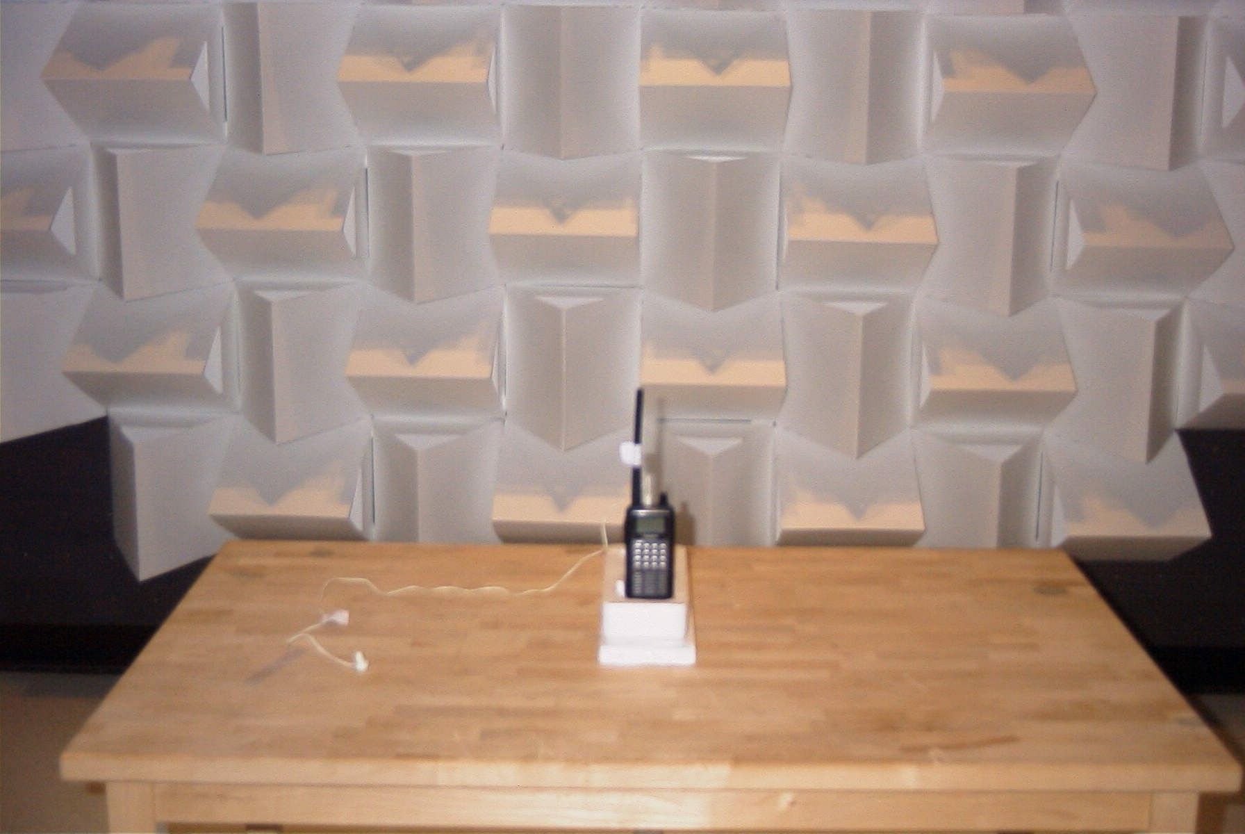
APPLICANT: UNIDEN AMERICA CORPORATION FCC ID: AMWUB330 REPORT #: U\Uniden AMW\1129AUT5\1129AUT5TestReport.doc TABLE OF CONTENTS TABLE OF CONTENTS LIST APPLICANT: UNIDEN AMERICA CORPORATION FCC ID: AMWUB330 TEST REPORT CONTAINING: PAGE 1......EQUIPMENT LIST PAGE 2......TEST PROCEDURE PAGE 3-5....RADIATED EMISSIONS TEST DATA PAGE 6......38 dB Rejection Ratio PAGE 7......TEST SETUP PHOTO EXHIBITS CONTAINING: BLOCK DIAGRAM SCHEMATICS INSTRUCTION MANUAL SAMPLE OF FCC ID LABEL AND SKETCH OF LOCATION RADIATED TEST SETUP PHOTOGRAPH EXTERNAL PHOTOS INTERNAL PHOTOS CIRCUIT DESCRIPTION APPLICANT: UNIDEN AMERICA CORPORATION FCC ID: AMWUB330 REPORT #: U\Uniden AMW\1129AUT5\1129AUT5TestReport.doc Page 1 of 7 APPLICANT: UNIDEN AMERICA CORPORATION FCC ID: AMWUB330 TEST EQUIPMENT LIST Device Manufacturer Model Serial Number Cal/Char Date Due Date 3/10-Meter OATS TEI N/A N/A Listed 3/27/04 3/26/07 3-Meter OATS TEI N/A N/A Listed 1/13/03 1/12/06 Biconnical Antenna Eaton 94455-1 1057 CAL 3/18/03 3/18/05 Biconnical Antenna Eaton 94455-1 1096 CAL 10/1/01 10/1/03 Biconnical Antenna Electro- Metrics BIA-25 1171 CAL 4/29/05 4/29/07 Blue Tower Quasi-Peak Adapter HP 85650A 2811A01279 CAL 4/13/05 4/13/07 Blue Tower RF Preselector HP 85685A 2620A00294 CAL 4/27/04 4/27/06 Blue Tower Spectrum Analyzer HP 8568B 2928A04729 2848A18049 CAL 4/13/05 4/13/07 LISN Electro- Metrics ANS-25/2 2604 CAL 8/27/04 8/27/06 LISN Electro- Metrics EM-7820 2682 CAL 4/28/05 4/28/07 Log- Periodic Antenna Eaton 96005 1243 CAL 5/8/03 5/8/05 APPLICANT: UNIDEN AMERICA CORPORATION FCC ID: AMWUB330 REPORT #: U\Uniden AMW\1129AUT5\1129AUT5TestReport.doc Page 2 of 7 TEST PROCEDURE GENERAL: This report shall NOT be reproduced except in full without the written approval of TIMCO ENGINEERING, INC. RADIATION INTERFERENCE: The test procedure used was ANSI STANDARD C63.4-2003 using a HEWLETT PACKARD spectrum analyzer with a preselector. The bandwidth of the spectrum analyzer was 100 kHz with an appropriate sweep speed. The analyzer was calibrated in dB above a microvolt at the output of the antenna. The resolution bandwidth was 100KHz and the video bandwidth was 300KHz. The ambient temperature of the UUT was 80oC with a humidity of 76%. FORMULA OF CONVERSION FACTORS: The Field Strength at 3m was established by adding the meter reading of the spectrum analyzer (which is set to read in units of dBuV) to the antenna correction factor supplied by the antenna manufacturer. The antenna correction factors are stated in terms of dB. The gain of the Preselector was accounted for in the Spectrum Analyzer Meter Reading. Example: Freq (MHz) METER READING + ACF = FS 33 20 dBuV + 10.36 dB = 30.36 dBuV/m @ 3m ANSI STANDARD C63.4-2003 10.1.7 MEASUREMENT PROCEDURES: The unit under test was placed on a table 80 cm high and with dimensions of 1m by 1.5m. The table used for radiated measurements is capable of continuous rotation. When an emission was found, the table was rotated to produce the maximum signal strength. At this point, the antenna was raised and lowered from 1m to 4m. The antenna was placed in both the horizontal and vertical planes. APPLICANT: UNIDEN AMERICA CORPORATION FCC ID: AMWUB330 REPORT #: U\Uniden AMW\1129AUT5\1129AUT5TestReport.doc Page 3 of 7 APPLICANT: UNIDEN AMERICA CORPORATION FCC ID: AMWUB330 NAME OF TEST: RADIATION INTERFERENCE RULES PART NUMBER: 15.109 REQUIREMENTS: 30 to 80 MHz: 40.0 dBuV/M @ 3 METERS 88 to 216 MHz: 43.5 dBuV/M 216 to 960 MHz: 46.0 dBuV/M ABOVE 960 MHz: 54.0 dBuV/M TEST RESULTS: A search was made of the spectrum from 30 to 1000 MHz and the measurements indicate that the unit DOES meet the FCC requirements. TEST DATA: Tuned Frequency MHz Emission Frequency MHz Meter Reading dBuV Ant. Polarity Coax Loss dB Correction Factor dB Field Strength dBuV/m Margin dB 0.3 265.95 13.6 V 1.03 12.76 27.39 18.61 0.3 265.95 17.4 H 1.03 13.24 31.67 14.33 0.6 266.17 13.1 V 1.03 12.76 26.89 19.11 0.6 266.17 17.6 H 1.03 13.25 31.88 14.12 1.2 266.81 13.8 V 1.03 12.77 27.60 18.40 1.2 266.81 18.3 H 1.03 13.27 32.60 13.40 1.2 266.85 14.1 V 1.03 12.77 27.90 18.10 1.2 266.85 18.6 H 1.03 13.27 32.90 13.10 21.0 286.66 12.8 V 1.07 13.63 27.50 18.50 21.0 286.66 17.2 H 1.07 14.10 32.37 13.63 25.0 290.65 13.2 V 1.08 13.81 28.09 17.91 25.0 290.65 18.2 H 1.08 14.11 33.39 12.61 40.8 306.44 13.3 V 1.11 15.38 29.79 16.21 40.8 306.44 18.2 H 1.11 15.59 34.90 11.10 54.0 319.55 14.0 V 1.12 15.05 30.17 15.83 54.0 319.55 21.0 H 1.12 15.25 37.37 8.63 54.1 319.65 14.3 V 1.12 15.04 30.46 15.54 54.1 319.65 20.7 H 1.12 15.24 37.06 8.94 72.5 338.15 14.3 V 1.14 14.52 29.96 16.04 72.5 338.15 20.5 H 1.14 15.12 36.76 9.24 107.9 373.55 14.9 V 1.17 14.80 30.87 15.13 107.9 373.55 16.4 H 1.17 15.27 32.84 13.16 118.8 384.45 12.9 H 1.18 15.58 29.66 16.34 118.8 384.45 15.0 V 1.18 15.11 31.29 14.71 APPLICANT: UNIDEN AMERICA CORPORATION FCC ID: AMWUB330 REPORT #: U\Uniden AMW\1129AUT5\1129AUT5TestReport.doc Page 4 of 7 APPLICANT: UNIDEN AMERICA CORPORATION FCC ID: AMWUB330 NAME OF TEST: RADIATION INTERFERENCE CONTINUED Tuned Frequency MHz Emission Frequency MHz Meter Reading dBuV Ant. Polarity Coax Loss dB Correction Factor dB Field Strength dBuV/m Margin dB 127.2 392.75 11.8 H 1.19 15.88 28.87 17.13 127.2 392.75 15.3 V 1.19 15.64 32.13 13.87 135.5 401.15 12.3 H 1.20 16.13 29.63 16.37 135.5 401.15 15.5 V 1.20 16.02 32.72 13.28 138.2 518.94 7.6 H 1.36 19.19 28.15 17.85 138.2 518.94 8.8 V 1.36 18.36 28.52 17.48 162.0 542.76 9.5 H 1.43 18.73 29.66 16.34 162.0 542.76 9.7 V 1.43 18.23 29.36 16.64 173.2 554.08 9.6 H 1.46 18.92 29.98 16.02 173.2 554.08 10.0 V 1.46 18.38 29.84 16.16 197.8 578.55 10.7 V 1.54 18.96 31.20 14.80 197.8 578.55 12.3 H 1.54 19.39 33.23 12.77 225.1 605.85 9.6 V 1.61 18.60 29.81 16.19 225.1 605.85 11.1 H 1.61 19.36 32.07 13.93 310.1 690.85 10.8 V 1.69 20.73 33.22 12.78 310.1 690.85 12.3 H 1.69 21.40 35.39 10.61 330.1 595.65 10.7 V 1.59 18.77 31.06 14.94 330.1 595.65 11.7 H 1.59 19.26 32.55 13.45 406.9 672.45 10.2 V 1.67 20.70 32.57 13.43 406.9 672.45 10.9 H 1.67 21.00 33.…
Text truncated - open the document above for the full version.
Contact Information
Applicant
Paul Roby
Test Firm
Timco Engineering, Inc.S Sanders
Technical Specifications
| # | Rule Parts | Frequency Range | Power Output |
|---|---|---|---|
| 6 | 15B | 894.0125 MHz - 956 MHz | - |
Other Applications from Uniden America Corporation
AMWUA2405
Apr 15, 2026RADAR DETECTOR
Equipment Class
JBP - Part 15 Class B Computing Device PeripheralAMWUA2406
Apr 15, 2026RADAR DETECTOR
Equipment Class
JBP - Part 15 Class B Computing Device PeripheralAMWUA2402
Jul 23, 2024RADAR DETECTOR
Equipment Class
CRD - Part 15 Radar Detector
AMWUA2404
Feb 17, 2024Wi-Fi Bluetooth Combo Module
Equipment Class
DTS - Digital Transmission System
AMWUA2301
Feb 15, 2023RADAR DETECTOR
Equipment Class
CRD - Part 15 Radar Detector