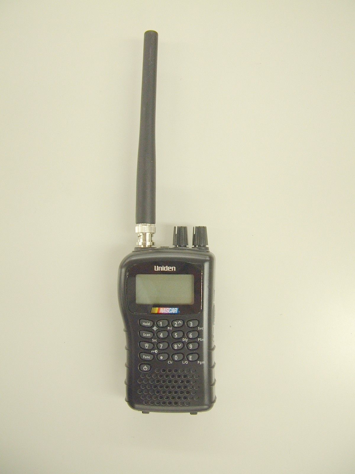
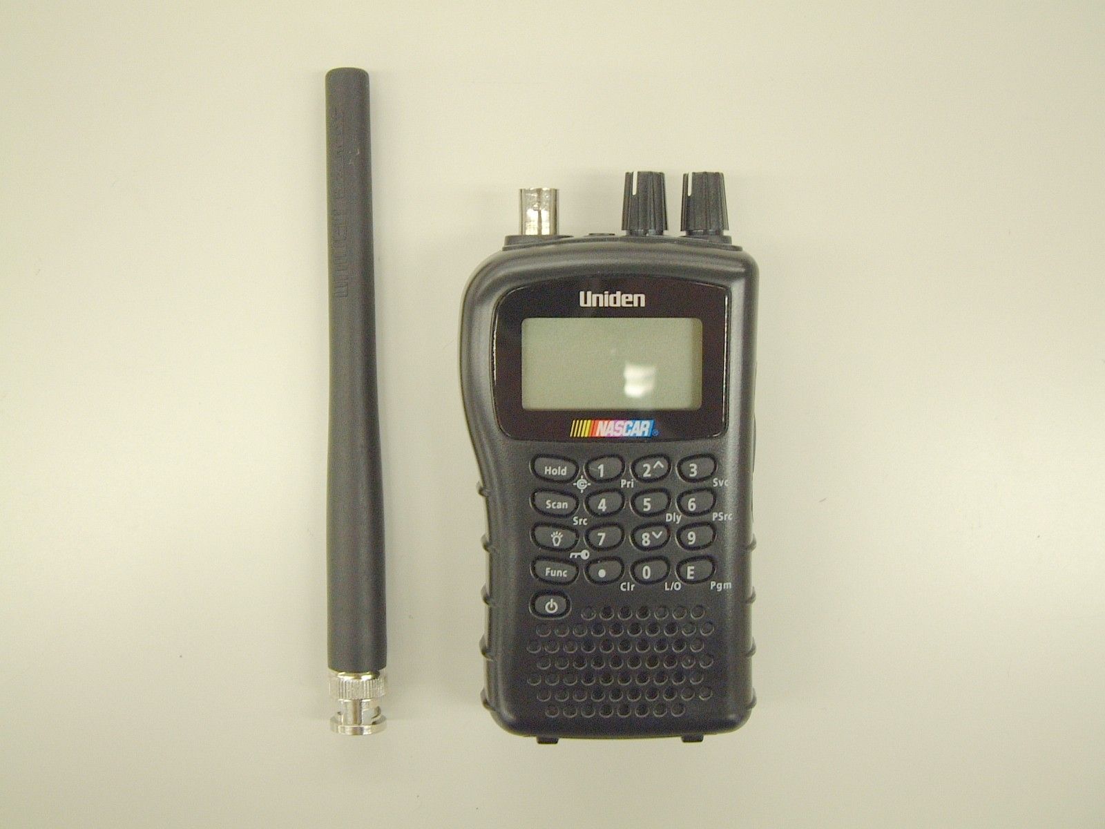
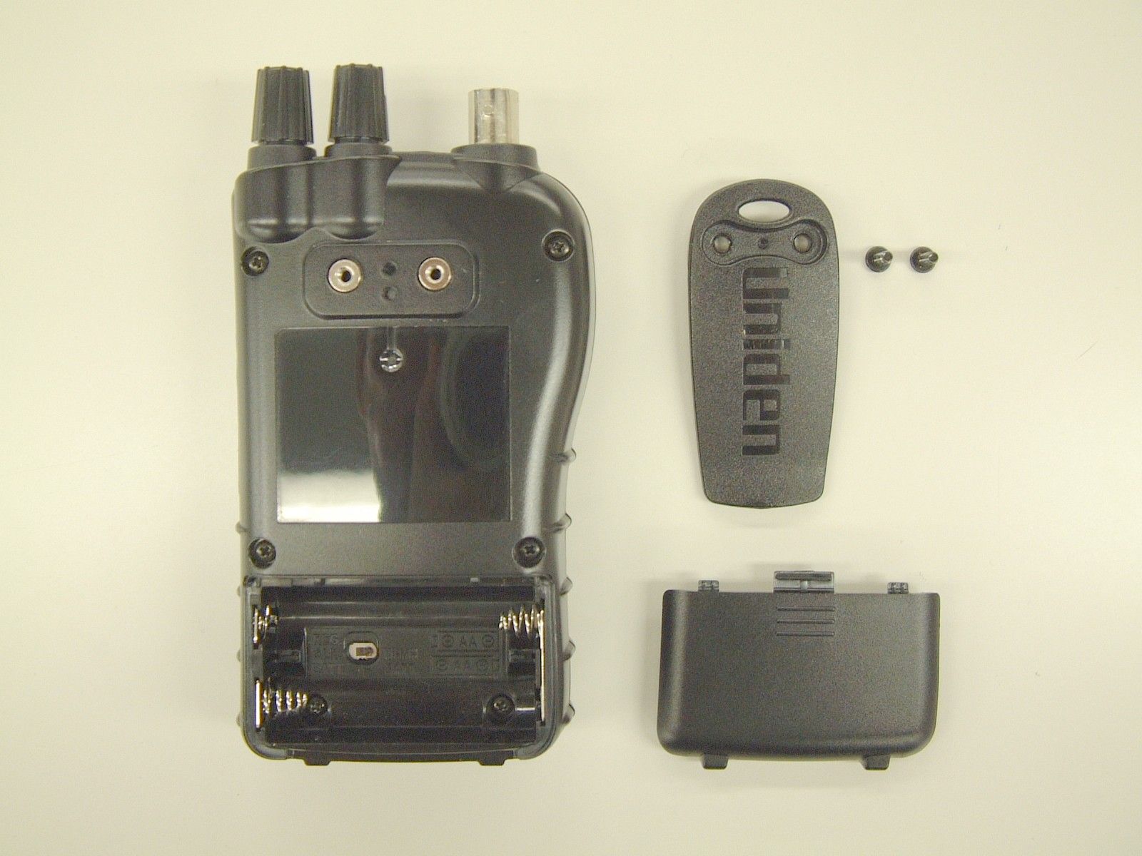
AMWUB348HANDHELD SCANNER
Uniden America Corporation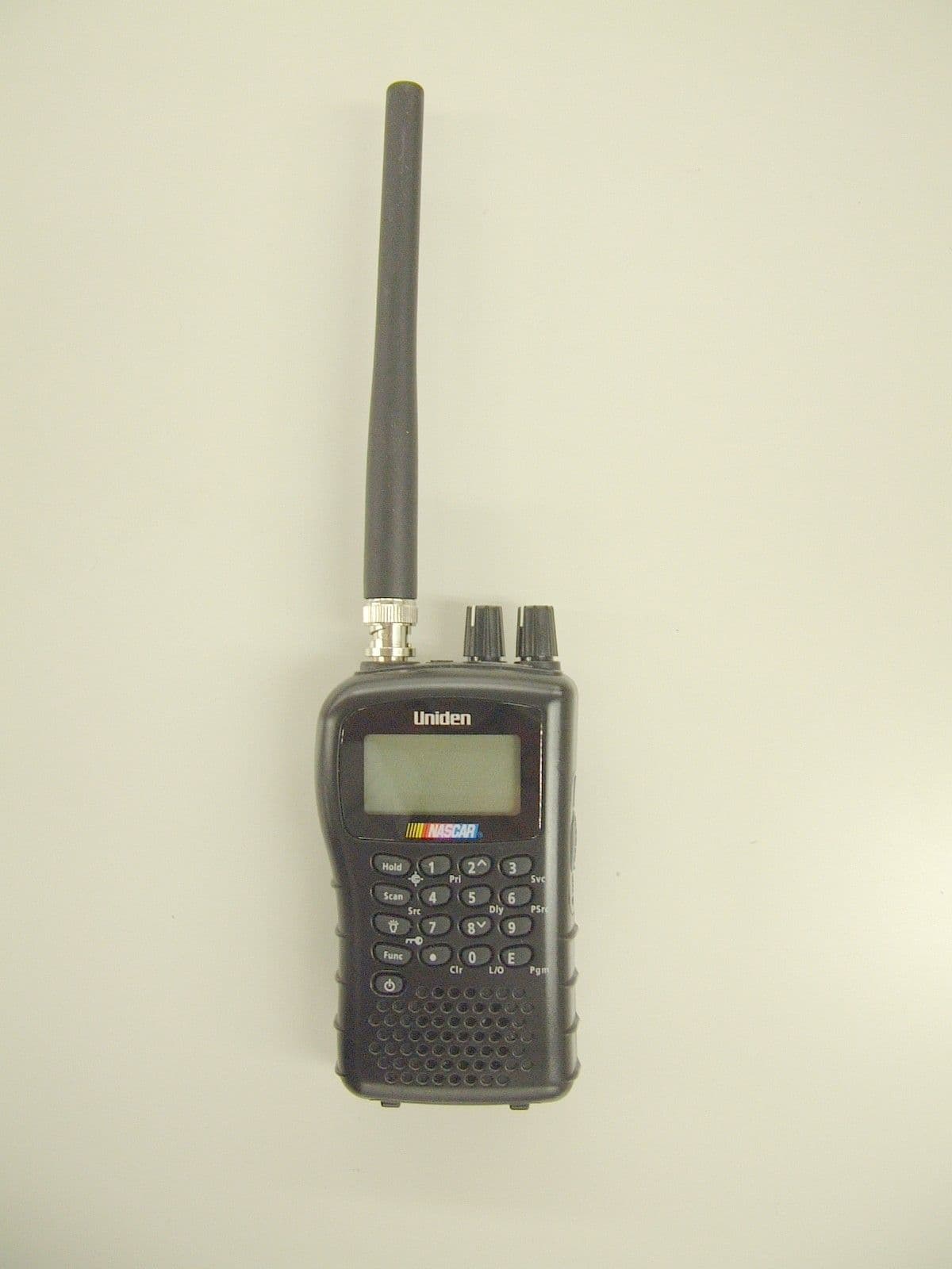
Click to zoom
Application Details
- Equipment Class
- CSR - Scanning Receiver
- Date of Grant
- Sep 24, 2006
- Application Purpose
- Original Equipment
- Date of Application
- Sep 21, 2006
- Equipment Note
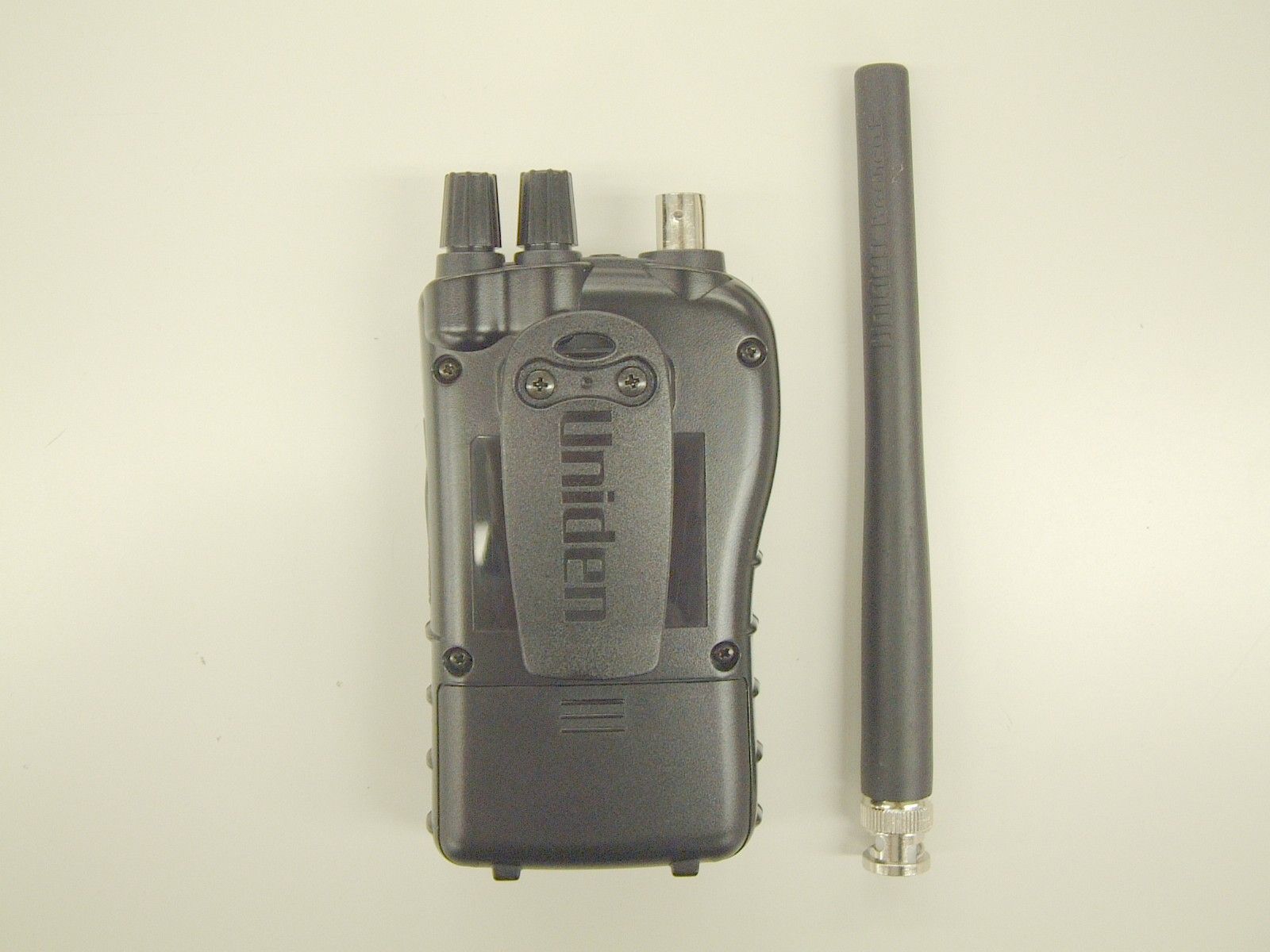
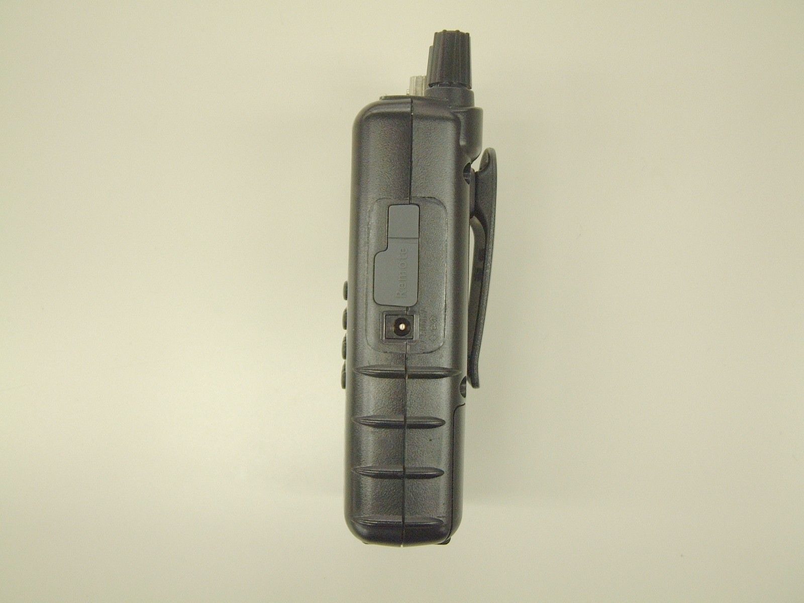
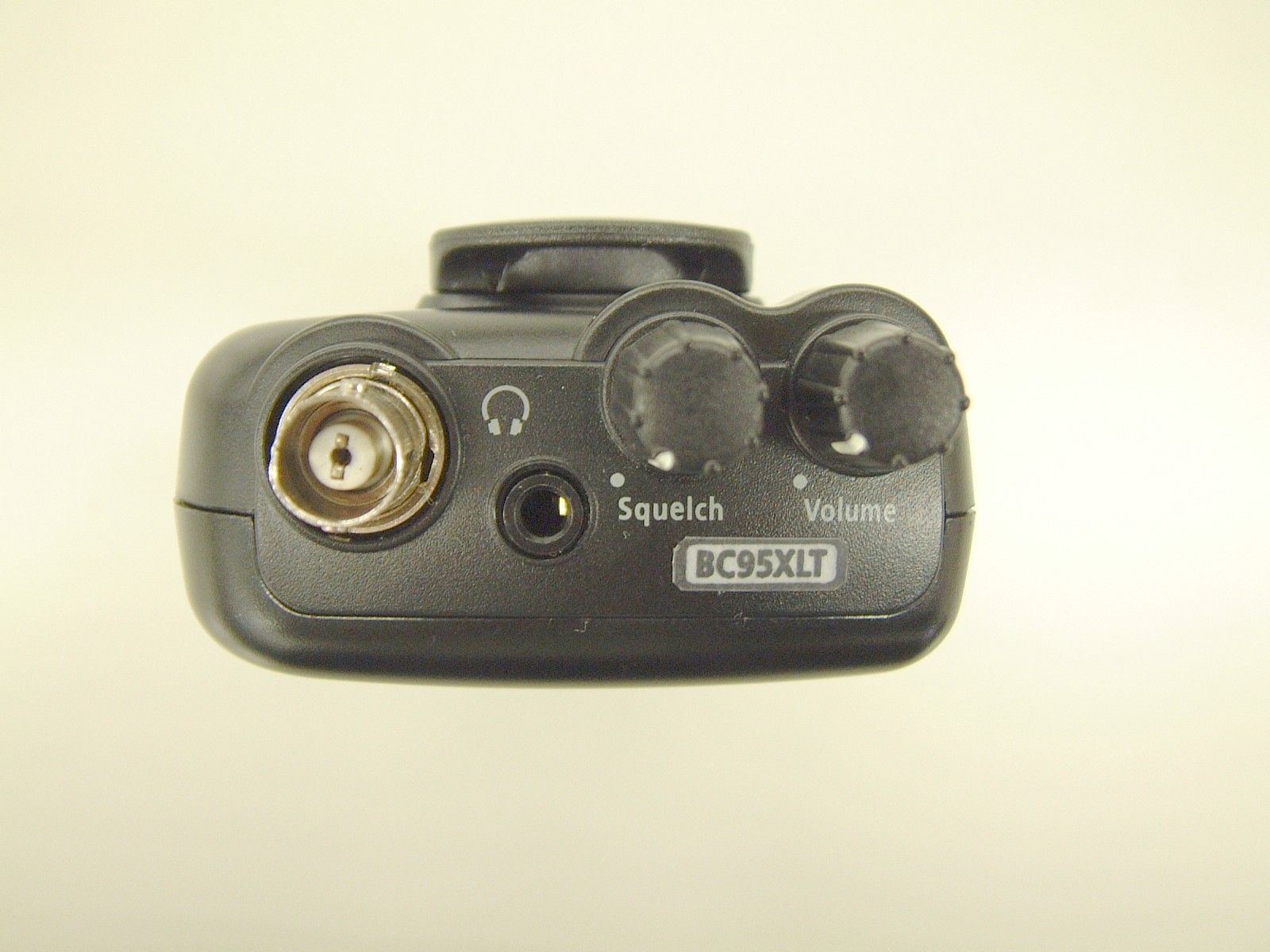
- HANDHELD SCANNER
- Frequency Range
- 894.01250000 - 956.00000000
- Company
- Uniden America Corporation
- Country
- United States
Documents & Files
Document Text
Text extracted from the exhibit documents filed with the FCC. Open a document above to read the original.
Attestation Statements
GENERAL INFORMATION General Information in accordance with the Federal Communications Commission Rules and Regulations, Volume II, Part 2. (1) Applicant: Uniden America Corporation 181 N. Country Club Road, P.O. Box 580 Lake City, South Carolina 29560 Mr. James R. Haynes, Vice President (2) FCC Identifier: FCC ID: AMWUB348 MODEL NO.: (3) Instruction Manual: Refer to User Manual (4) Circuit Description: Refer to Operational Description (5) Circuit & Block Diagrams: Refer to Schematics Block diagrams (6) Measurement Data: Refer to Test Report Standard Test Conditions: The following conditions and procedures were followed during testing of the equipment. Room Temperature: 23 - 27 Degrees Celsius Room Humidity: 40 - 60 % Note 1: This equipment is intended to use with; 2 AA Alkaline Batteries (3V DC), or 2 AA Rechargeable Ni-MH Batteries (2.4V DC), or AC Adapter (6 VDC 500mA) Note 2: Prior to testing, the unit is tuned-up according to the manufacturer's alignment procedure. All presented data will represent the "worst case" parameter being measured. (7) Photographs & Equipment Identification: Refer to ID Label/Location Info & External Photos (8) Peripheral or Accessory Device: Not used (9) Transition provisions in section 15.37 Rules: This equipment complies with the new Part 15 of FCC rules and is not affected by section 15.37. (10) Decoding the Emergency Broadcast System Attention Signal: Not Applicable (11) Direct Sequence Spread Spectrum Transmitter: Not Applicable (12) Compliance to Cellular Band Exclusion: Pursuant to the requirements contained in Part 15.121 of the Commission's Rules, this scanning receiver does not have the capability of tuning the frequencies assigned to the Domestic Public Cellular Radio Telecommunications Service. In this circuitry, this device is not readily alterable to restore the cellular band coverage because the inventory of frequencies contained within this band is not available in the microprocessor. Also, the microprocessor is fixed soldered and not easily removable. In addition, the critical circuitry is "hardened" with a black epoxy that covers the area of the circuitry that might be modified to circumvent the design efforts referenced above. Therefore, since the clipping of leads; or the installation of a simple component such as a diode, resistor, or a jumper wire; or the reprogramming of any semiconductor device contained within this unit cannot be accomplished using a special access code or a personal computer; This is to certify that the conditions mandated in part 15.121 have been met.
ID Label/Location Info
ID Label/Location Info Equipment Identification Label The FCC Label complies with the section 2.925(d) of the FCC Rules and will be permanently affixed to the equipment. Size: 41 mm (W) by 35 mm (H)
Test Report
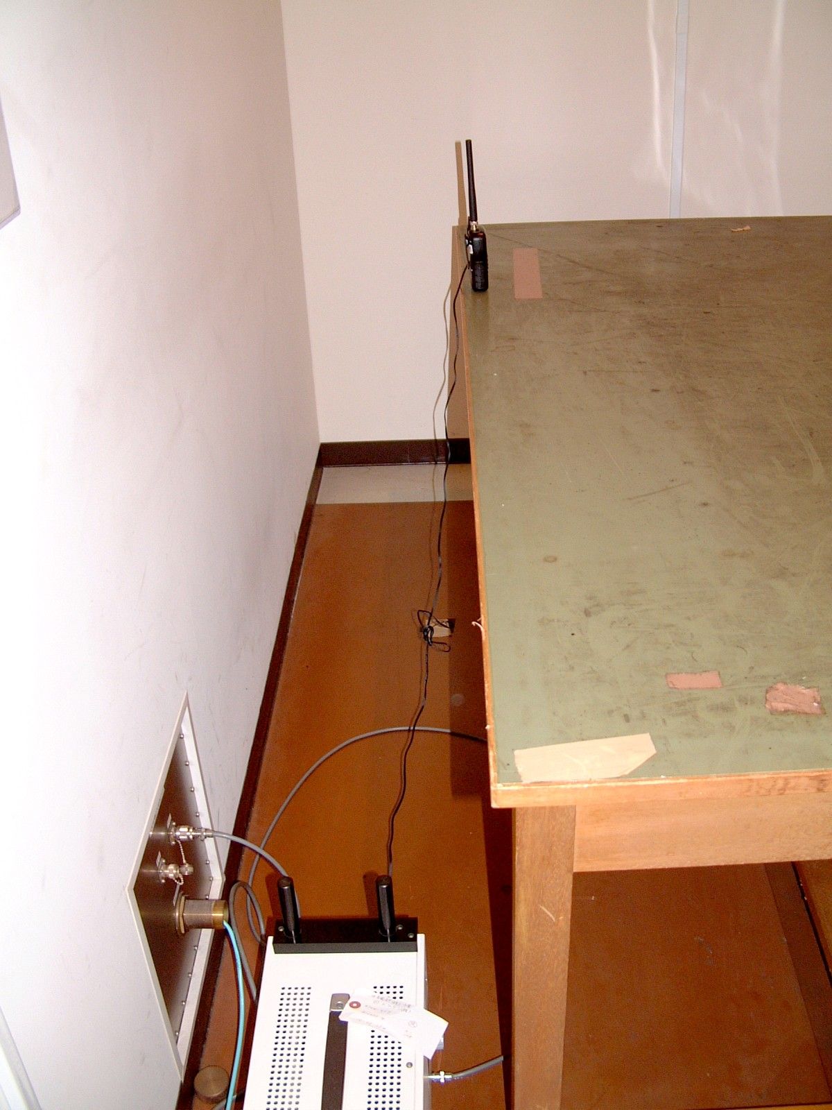
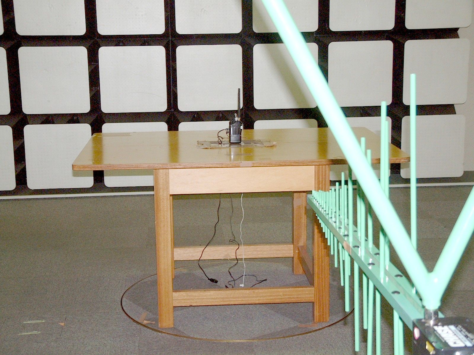
Test Report TEST PROCEDURES AND TEST SITE DESCRIPTION 200CH COMPACT SCANNER MEASUREMENT ITEMS 5-1 Field Strength of Spurious Radiated Emission 5-2 Power Line Conducted Emissions 5-3 Cellular image rejection NOTE: Measurements in Scan Mode vs. Non-Scan Mode -------------------------------------------------- The measurement data reported in the original file represented a non-scan mode for both of power line conducted emission and spurious radiated emission because no emission level exceeded that of the levels in the scan mode. In scan mode, the receiver only stays at a particular frequency for as short as 20 ms in certain channels as the scanning interval may change depending on the number of the memorized channels. This means that true emission levels may change along with the number of the memorized channels in the scanning mode due to changes in the duty cycle of the emission level. Therefore, we measured the device where each memorized channel was scanned for 3 different points of frequencies in each receiver coverage range as shown in the original file and we confirm that no emission level exceeds the level reported from the ones measured in the non-scan mode. 5-1 Field Strength of Spurious Radiated Emission Test procedure: The measurements were performed in accordance with the ANSI C63.4- 2003. Field Strength measurements of radiated spurious emissions were made at the open test site of a 3 meter range maintained by Uniden Corporation in Japan. Complete description and measurement data of this test site have been placed on file with the Commission. The radio frequency spectrum was scanned in the range of 30 MHz to the 10th harmonic in accordance with the section 15.33(a) of the FCC Rules. The frequency below 1 GHz, the measurement was carried out by using CISPR quasi-peak detector, AGILENT E7400A the Spectrum Analyzer in accordance with the sections 15.33(a) and 15.35(a). The frequency above 1 GHz, using the AGILENT E7400A Spectrum Analyzer in accordance with the section 15.35(b) carried out the measurement. A bilog antenna CBL6112A was used to cover the range from 30 MHz to 1000 MHz. Narrowband tuned dipole antennas were used over the entire 30 to 1000 MHz range for precision measurements of field strength. Above 1000 MHz, a horn antenna EMCO 3115 was used. For each spurious or harmonic frequency, the antenna was raised and lowered to obtain a maximum reading on the Spectrum Analyzer with antenna horizontally polarized. Then the turntable, on which the equipment under test was placed, was rotated a minimum of 360 degrees to further increase the reading on the Spectrum Analyzer. For testing small and/or handheld product, the measurement was performed in 3 orthogonal planes (X, Y, Z). This procedure was repeated with the antenna vertically polarized. The equipment under test was connected with all of placed in its normal operating position on a turntable approximately 0.8 meter in height. During the measurement, full-featured accessory cables were connected with the equipment under test. In order to convert the measured emission levels into field strength in dBuV/m, the actual field strength (Ef) is determined by algebraically adding the measured emission level (Em) and the antenna correction factor (ACF) including the cable loss at the appropriate frequency. Ef [dBuV/m] = Em [dBuV/m] + ACF [dB] Ef [dBuV/m] = Em [dBuV/m] + ACF [dB] FCC Limits: Frequency Field Strength at 3 meter 30 - 88 MHz 40 dBuV/m (100 uV/m) 88 - 216 MHz 43.5 dBuV/m (150 uV/m) 216 - 960 MHz 46 dBuV/m (200 uV/m) Above 960 MHz 54 dBuV/m (500 uV/m) Test Results: Refer to the attached test reports. All emissions not reported were more than 20 dB below the limits. 5-2 Power Line Conducted Emissions Test Procedure: The measurements were performed in accordance with the ANSI C63.4- 1992. During the measurements, a standard voltage source is fed into the unit under test through a power line impedance stabilization network. FCC Limit: The radio frequency voltage that is conducted back into the AC power line on any frequencies within the band from 150kHz to 30MHz shall not exceed the following limitation. REQUIREMENTS: FREQUENCY(MHz) LEVEL (dBuV) 0.150-0.50 66 to 56 QP 56 to 46 Ave 0.50-5.0 56 QP 46 Ave 5.0-30.0 60 QP 50 Ave Test Results: Refer to the attached test reports. All emissions not reported were more than 20 dB below the limits. 5-3 Cellular image rejection See test result. Test set-up: SSGEUTSINAD METER Dummy load 8 ohm ANTSP JACK
Contact Information
Applicant
Paul Roby
Test Firm
Uniden CorporationKeizo Fujiwara
Technical Specifications
| # | Rule Parts | Frequency Range | Power Output |
|---|---|---|---|
| 7 | 15B | 894.0125 MHz - 956 MHz | - |
Other Applications from Uniden America Corporation
AMWUA2405
Apr 15, 2026RADAR DETECTOR
Equipment Class
JBP - Part 15 Class B Computing Device PeripheralAMWUA2406
Apr 15, 2026RADAR DETECTOR
Equipment Class
JBP - Part 15 Class B Computing Device PeripheralAMWUA2402
Jul 23, 2024RADAR DETECTOR
Equipment Class
CRD - Part 15 Radar Detector
AMWUA2404
Feb 17, 2024Wi-Fi Bluetooth Combo Module
Equipment Class
DTS - Digital Transmission System
AMWUA2301
Feb 15, 2023RADAR DETECTOR
Equipment Class
CRD - Part 15 Radar Detector