AMWUB351MOBILE TYPE SCANNING RECEIVER
Uniden America Corporation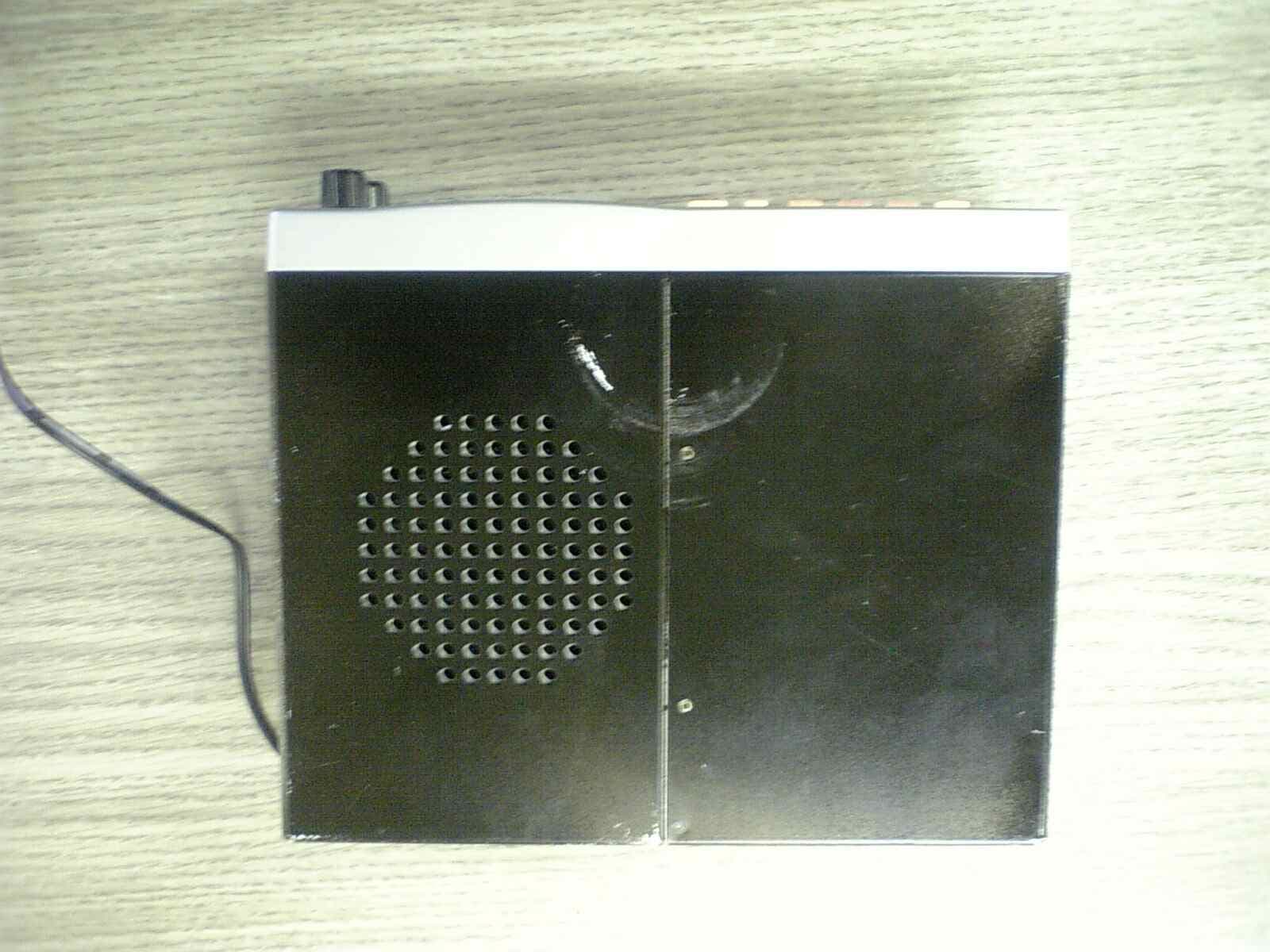
Click to zoom
Application Details
- Equipment Class
- CSR - Scanning Receiver
- Date of Grant
- Dec 27, 2007
- Application Purpose
- Original Equipment
- Date of Application
- Dec 27, 2007
- Equipment Note
- MOBILE TYPE SCANNING RECEIVER
- Frequency Range
- 894.01250000 - 956.00000000
- Company
- Uniden America Corporation
- Country
- United States
Documents & Files
Document Text
Text extracted from the exhibit documents filed with the FCC. Open a document above to read the original.
Users Manual
20-160 PRO-160 1,000 ch Trunking Desktop/Mobile Scanner Thank you for purchasing your PRO-160 1,000 Channel Trunking Desktop/Mobile Scanner from RadioShack. Your scanner is one of a new generation of scanners designed to track Motorola® Type I, Type II, hybrid analog, and many other systems. what’s included Scanner AC adapter DC cable with fuse Antenna DIN sleeve Removal keys (2) Mounting bracket Knobs (2) Lock washers (2) Screws (2) Rubber feet (4) User’s guide Preprogrammed frequency sheet Quick Start step 1: installing your scanner You can mount your scanner as a base station or in your vehicle. If you are unsure how to install our scanner in your vehicle, consult your automobile manufacturer, dealer, or a qualified installer. base station Attach the four protective rubber feet to the mounting bracket when you use the scanner as a base station on a flat surface such as a desk, shelf, or table. Because the speaker is on the bottom of the scanner, you can use the mounting bracket to elevate your scanner off the surface for better sound. vehicle mounting To mount your scanner under or over the dashboard, use the mounting bracket. Before installing, confirm that your scanner fits in the desired mounting area and you have all the necessary materials to complete the task. IMPORTANT: AVOID AIRBAG DEPLOYMENT ZONES. This can prevent the airbag from performing properly and result in injury. 1. Use the supplied mounting bracket as a template to mark positions for the two mounting screws. 2. At the marked positions, drill holes slightly smaller than the screws. When drilling holes, be sure to avoid obstructions and wires behind the mounting surface. 3. Attach the mounting bracket to the surface using the supplied screws. 4. Slide the scanner into the bracket, aligning the scanner’s holes with the holes in the bracket, and then screw the mounting knobs into the scanner. Your scanner requires a 2 x 7-1/8 x 5-5/16 inch (50 x 180 x 135mm) mounting area. Allow an additional 2-3/8 inch (60 mm) space behind the scanner for connectors and wires. 1. Remove the four rear screws that secure the outer metal case and pull off the case with care. 2. Insert the DIN sleeve into the opening in your dashboard, lip facing out. 3 . Push out the top and bottom tabs to hold the sleeve firmly in place. 4. Slowly slide the scanner into the sleeve until it locks in place. Note: • When mounting in your dashboard, you will need to connect an external antenna and an external speaker. • To remove your scanner from the DIN sleeve, insert the two removal keys straight into the scanner’s front panel and pull the scanner out. step 2: power your scanner You can power your scanner from a wall outlet, through your vehicle’s ignition, or from your vehicle’s cigarette lighter or power port. You must use a Class 2 power source that supplies 12V DC and delivers at least 500mA. Its center tip must be set to positive and its plug must fit the scanner’s DC 12V jack. Using an adapter that does not meet these specifications could damage the scanner or the adapter. wall outlet To prevent electric shock, do not use the AC adapter’s polarized plug with an extension cord, receptacle, or other outlet unless you can fully insert the blades. 1. Connect the tip of the supplied AC adapter to the DC 12V jack. 2. Plug the AC adapter into your wall outlet. DC 12V Power source connection. vehicle cigarette lighter or power port To power your scanner from your vehicle’s 12V power source, use a 12V DC cigarette-lighter adapter (not supplied, available at RadioShack). Note: If you use a cigarette-lighter adapter, you might hear some electrical interference from your engine while scanning. This is normal. vehicle ignition (negative ground only) Note: If you are not experienced in connecting accessories to the vehicle fuse box, use a certified installer. 1. Disconnect the cable from the negative (-) terminal of your vehicle’s battery. 2. Ground the black wire of the supplied DC power cord to your vehicle’s chassis. The grounding screw must make complete contact with the metal frame of your vehicle. 3. Connect the red wire of the supplied DC power cord to a voltage source that turns on and off with the ignition switch, such as a spare accessory terminal in your vehicle’s fuse box. 4 . Insert the adapter’s barrel plug into the scanner’s DC 12V jack. 5. Reconnect the cable to the negative (-) terminal of your vehicle’s battery. step 3: connect your scanner antenna Expand the antenna according to the frequencies you want to monitor: Frequency ..................................... Antenna Length 25-174 MHz .....................Extend fully (4 segments) 320-512 MHz ................... Extend half (2 segments) 806-1300 MHz ................Collapse fully (1 segment) The scanner’s ANT jack supports a variety of antennae (available at RadioShack). Note: • An external antenna is optional if you use your scanner as a base station. If you mount your scanner in your vehicle, you will need to connect an external antenna. • The antenna should be as high as possible and vertical for best performance. • Keep the antenna and cable as far as possible from sources of electrical noise, such as appliances or other radios. Always use 50-ohm coaxial cable, such as RG-58 or RG-8, to connect an outdoor antenna. For lengths over 50 feet, use RG-8 low-loss dielectric coaxial cable. You also may need a BNC adapter (not supplied). external speaker To use an external speaker (available at your local RadioShack store), plug the speaker’s 1/8 inch (3.5 mm) plug into the scanner’s EXT SP jack. Note: Connecting an external speaker mutes the scanner’s internal speaker. ANT Match the antenna connector arrow to the ANT jack’s upper projection. CAUTION: Use extreme caution when installing or removing an outdoor antenna. If the antenna starts to fall, let it go! If the antenna touches a power line, touching the antenna, mast, cable, or guy wires can cause electrocution and death. Call the power com…
Text truncated - open the document above for the full version.
Attestation Statements
GENERAL INFORMATION General Information in accordance with the Federal Communications Commission Rules and Regulations, Volume II, Part 2. (1) Applicant: Uniden America Corporation 181 N. Country Club Road, P.O. Box 580 Lake City, South Carolina 29560 Mr. James R. Haynes, Vice President (2) FCC Identifier: FCC ID: AMWUB351 MODEL NO.: 20-160 (3) Instruction Manual: Refer to User Manual (4) Circuit Description: Refer to Operational Description (5) Circuit & Block Diagrams: Refer to Schematics Block diagrams (6) Measurement Data: Refer to Test Report Standard Test Conditions: The following conditions and procedures were followed during testing of the equipment. Room Temperature: 23 - 27 Degrees Celsius Room Humidity: 40 - 60 % Note 1: This equipment is intended to use with; 12Vdc –or- AC Adapter 12V DC Note 2: Prior to testing, the unit is tuned-up according to the manufacturer's alignment procedure. All presented data will represent the "worst case" parameter being measured. (7) Photographs & Equipment Identification: Refer to ID Label/Location Info & External Photos (8) Peripheral or Accessory Device: Not used (9) Transition provisions in section 15.37 Rules: This equipment complies with the new Part 15 of FCC rules and is not affected by section 15.37. (10) Decoding the Emergency Broadcast System Attention Signal: Not Applicable (11) Direct Sequence Spread Spectrum Transmitter: Not Applicable (12) Compliance to Cellular Band Exclusion: Pursuant to the requirements contained in Part 15.121 of the Commission's Rules, this scanning receiver does not have the capability of tuning the frequencies assigned to the Domestic Public Cellular Radio Telecommunications Service. In this circuitry, this device is not readily alterable to restore the cellular band coverage because the inventory of frequencies contained within this band is not available in the microprocessor. Also, the microprocessor is fixed soldered and not easily removable. In addition, the critical circuitry is "hardened" with a black epoxy that covers the area of the circuitry that might be modified to circumvent the design efforts referenced above. Therefore, since the clipping of leads; or the installation of a simple component such as a diode, resistor, or a jumper wire; or the reprogramming of any semiconductor device contained within this unit cannot be accomplished using a special access code or a personal computer; This is to certify that the conditions mandated in part 15.121 have been met.
Cover Letter(s)
REMINDER ABOUT CONFIDENTIALITY December 21, 2007 To: Federal Communications Commission Equipment Authorization Branch Laboratory Division Office of Engineering and Technology 7435 Oakland Mills Road Columbia, Maryland 21046 Subject: Data for FCC Certification Applicant: Uniden America Corporation 181 N. Country Club Road, P.O. Box 580 Lake City, South Carolina 29560 James R. Haynes, Vice President, Engineering and Regulatory Affairs TYPE OF EQUIPMENT: Scanning Receiver FCC IDENTIFIER: AMWUB351 Dear Sir or Madam: Some of the material included in this application contains trade secrets and proprietary information not customarily released to the public. Because public disclosure of the material might be harmful if information used in this application were used to modify the unit to illegally scan or tune Cellular Radio Service channels, this letter is to remind all persons involved that scanning receivers are automatically protected under 47CFR Section 0.457(d)(1)(ii) that the following be should withheld: Circuit Description Schematic Diagrams Block Diagrams Please contact the undersigned if you have any questions or need any further information. Regards, James R. Haynes Vice President, Engineering and Regulatory Affairs
ID Label/Location Info
ID Label/Location Info Equipment Identification Label The FCC Label complies with the section 2.925(d) of the FCC Rules and will be permanently affixed to the equipment. Size: 120 mm (W) by 12 mm (H) CAT.NO. 20-160 SCANNING RECEIVER PRO-160 FCC ID: AMWUB351
Test Report
Test Report TEST PROCEDURES AND TEST SITE DESCRIPTION MEASUREMENT ITEMS 5-1 Field Strength of Spurious Radiated Emission 5-2 Power Line Conducted Emissions 5-3 Cellular image rejection NOTE: Measurements in Scan Mode vs. Non-Scan Mode -------------------------------------------------- The measurement data reported in the original file represented a non-scan mode for both of power line conducted emission and spurious radiated emission because no emission level exceeded that of the levels in the scan mode. In scan mode, the receiver only stays at a particular frequency for as short as 20 ms in certain channels as the scanning interval may change depending on the number of the memorized channels. This means that true emission levels may change along with the number of the memorized channels in the scanning mode due to changes in the duty cycle of the emission level. Therefore, we measured the device where each memorized channel was scanned for 3 different points of frequencies in each receiver coverage range as shown in the original file and we confirm that no emission level exceeds the level reported from the ones measured in the non-scan mode. 5-1 Field Strength of Spurious Radiated Emission Test procedure: The measurements were performed in accordance with the ANSI C63.4- 2003. Field Strength measurements of radiated spurious emissions were made at the open test site of a 3 meter range maintained by Uniden Corporation in Japan. Complete description and measurement data of this test site have been placed on file with the Commission. The radio frequency spectrum was scanned in the range of 30 MHz to the 10th harmonic in accordance with the section 15.33(a) of the FCC Rules. The frequency below 1 GHz, the measurement was carried out by using CISPR quasi-peak detector, AGILENT E7400A the Spectrum Analyzer in accordance with the sections 15.33(a) and 15.35(a). The frequency above 1 GHz, using the AGILENT E7400A Spectrum Analyzer in accordance with the section 15.35(b) carried out the measurement. A bilog antenna CBL6112A was used to cover the range from 30 MHz to 1000 MHz. Narrowband tuned dipole antennas were used over the entire 30 to 1000 MHz range for precision measurements of field strength. Above 1000 MHz, a horn antenna EMCO 3115 was used. For each spurious or harmonic frequency, the antenna was raised and lowered to obtain a maximum reading on the Spectrum Analyzer with antenna horizontally polarized. Then the turntable, on which the equipment under test was placed, was rotated a minimum of 360 degrees to further increase the reading on the Spectrum Analyzer. For testing small and/or handheld product, the measurement was performed in 3 orthogonal planes (X, Y, Z). This procedure was repeated with the antenna vertically polarized. The equipment under test was connected with all of placed in its normal operating position on a turntable approximately 0.8 meter in height. During the measurement, full-featured accessory cables were connected with the equipment under test. In order to convert the measured emission levels into field strength in dBuV/m, the actual field strength (Ef) is determined by algebraically adding the measured emission level (Em) and the antenna correction factor (ACF) including the cable loss at the appropriate frequency. Ef [dBuV/m] = Em [dBuV/m] + ACF [dB] Ef [dBuV/m] = Em [dBuV/m] + ACF [dB] FCC Limits: Frequency Field Strength at 3 meter 30 - 88 MHz 40 dBuV/m (100 uV/m) 88 - 216 MHz 43.5 dBuV/m (150 uV/m) 216 - 960 MHz 46 dBuV/m (200 uV/m) Above 960 MHz 54 dBuV/m (500 uV/m) Test Results: Refer to the attached test reports. All emissions not reported were more than 20 dB below the limits. 5-2 Power Line Conducted Emissions Test Procedure: The measurements were performed in accordance with the ANSI C63.4- 2003. During the measurements, a standard voltage source is fed into the unit under test through a power line impedance stabilization network. FCC Limit: The radio frequency voltage that is conducted back into the AC power line on any frequencies within the band from 150kHz to 30MHz shall not exceed the following limitation. REQUIREMENTS: FREQUENCY(MHz) LEVEL (dBuV) 0.150-0.50 66 to 56 QP 56 to 46 Ave 0.50-5.0 56 QP 46 Ave 5.0-30.0 60 QP 50 Ave Test Results: Refer to the attached test reports. All emissions not reported were more than 20 dB below the limits. 5-3 Cellular image rejection See test result. Test set-up: SSGEUTSINAD METER Dummy load 8 ohm ANTSP JACK
Contact Information
Applicant
Paul Roby
Test Firm
Uniden CorporationKeizo Fujiwara
Technical Specifications
| # | Rule Parts | Frequency Range | Power Output |
|---|---|---|---|
| 5 | 15B | 894.0125 MHz - 956 MHz | - |
Other Applications from Uniden America Corporation
AMWUA2405
Apr 15, 2026RADAR DETECTOR
Equipment Class
JBP - Part 15 Class B Computing Device PeripheralAMWUA2406
Apr 15, 2026RADAR DETECTOR
Equipment Class
JBP - Part 15 Class B Computing Device PeripheralAMWUA2402
Jul 23, 2024RADAR DETECTOR
Equipment Class
CRD - Part 15 Radar Detector
AMWUA2404
Feb 17, 2024Wi-Fi Bluetooth Combo Module
Equipment Class
DTS - Digital Transmission System
AMWUA2301
Feb 15, 2023RADAR DETECTOR
Equipment Class
CRD - Part 15 Radar Detector