AMWUC354EWCIC T system w/ Weather Sensor Indicator
Uniden America Corporation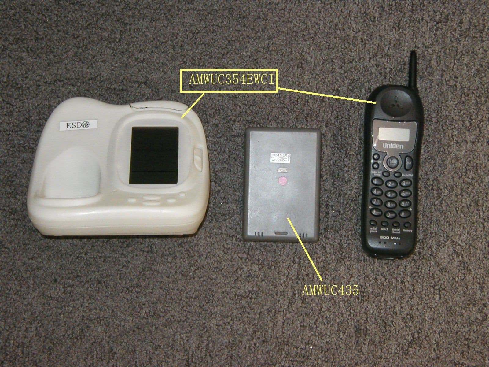
Click to zoom
Application Details
- Equipment Class
- DXX - Part 15 Low Power Communication Device Transmitter
- Date of Grant
- Jun 10, 2004
- Application Purpose
- Original Equipment
- Date of Application
- Jun 10, 2004
- Equipment Note
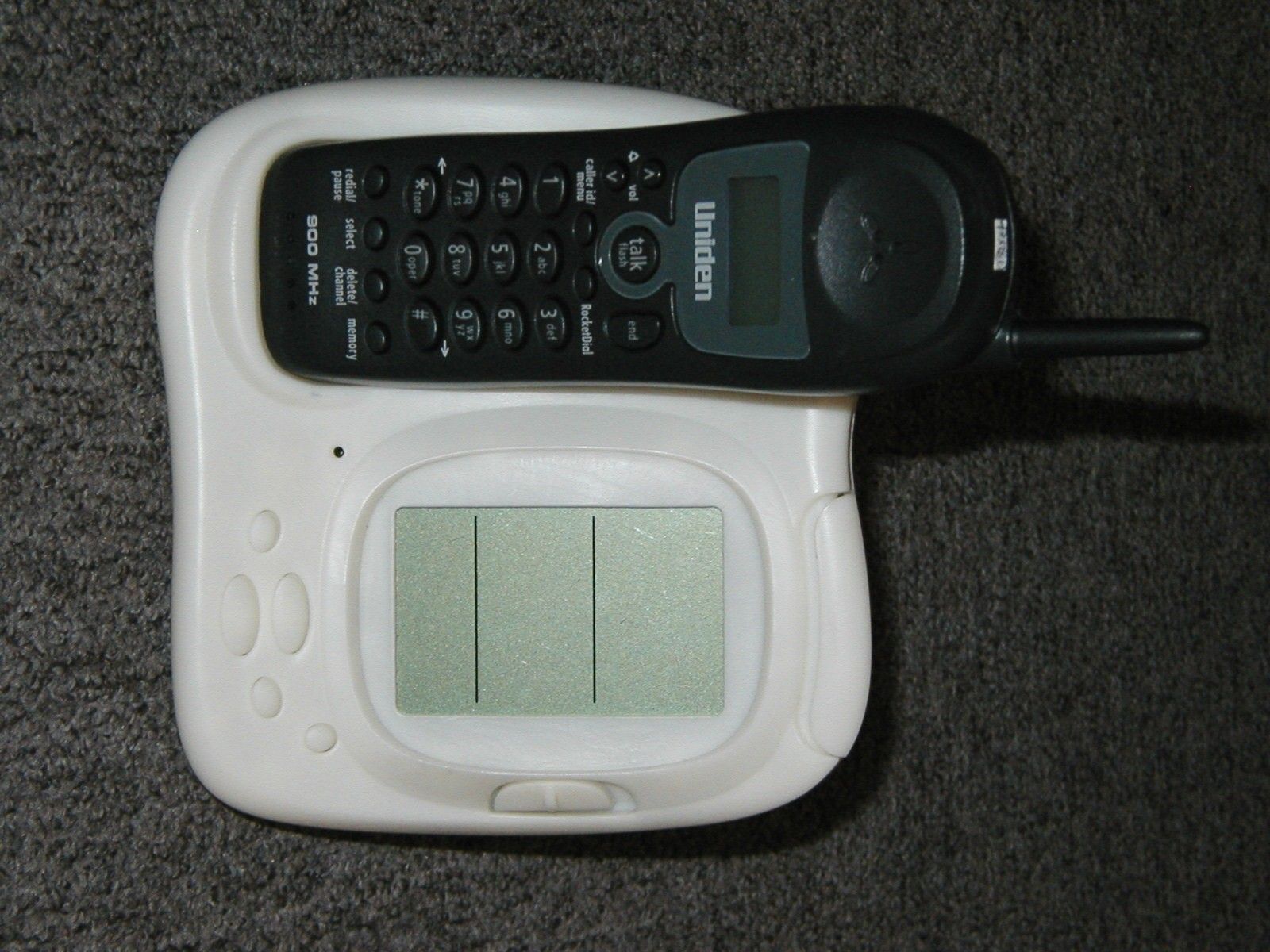
- C T system w/ Weather Sensor Indicator
- Frequency Range
- 925.61067700 - 927.69874500
- Company
- Uniden America Corporation
- Country
- United States
Documents & Files
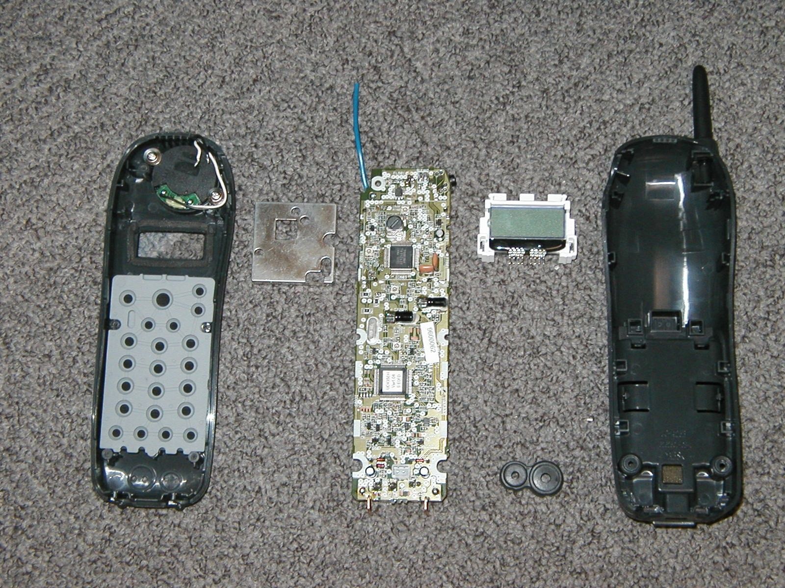
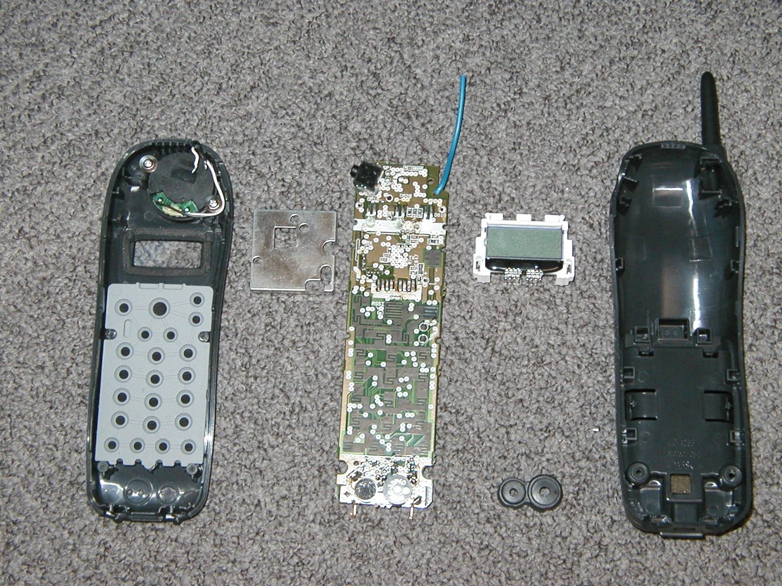
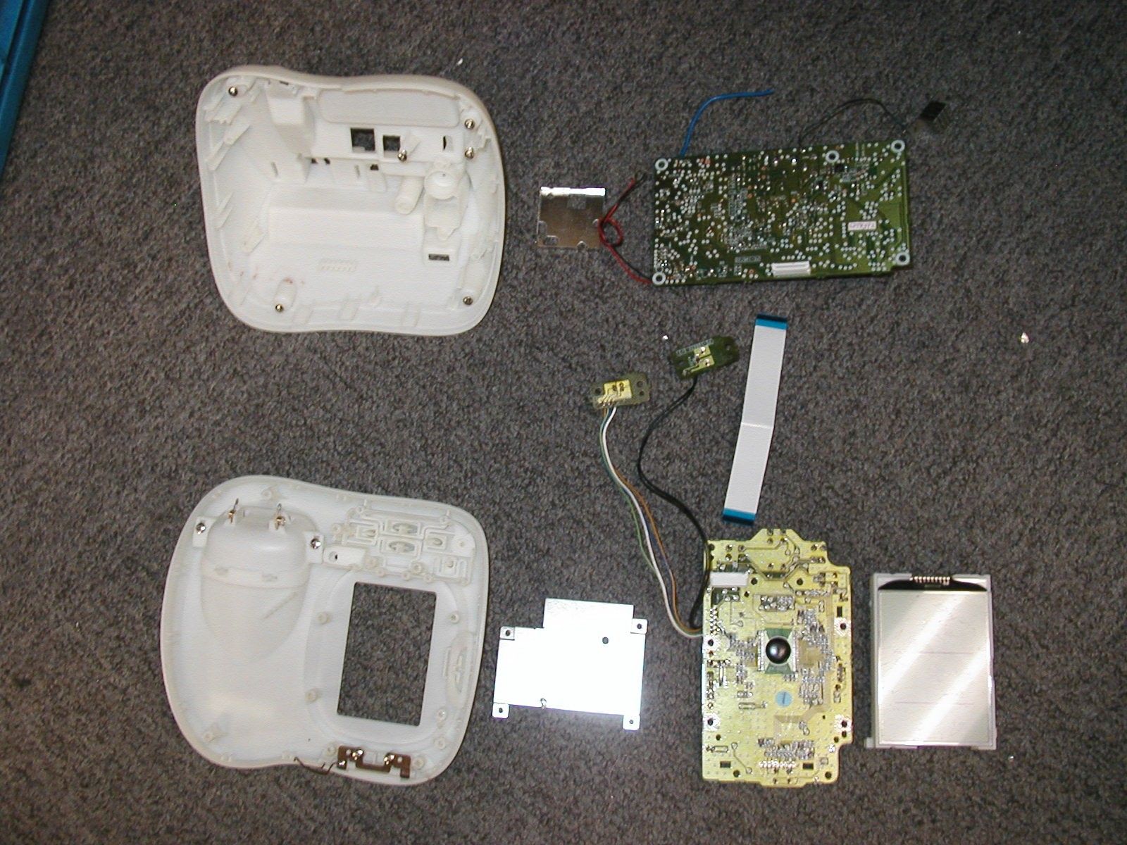
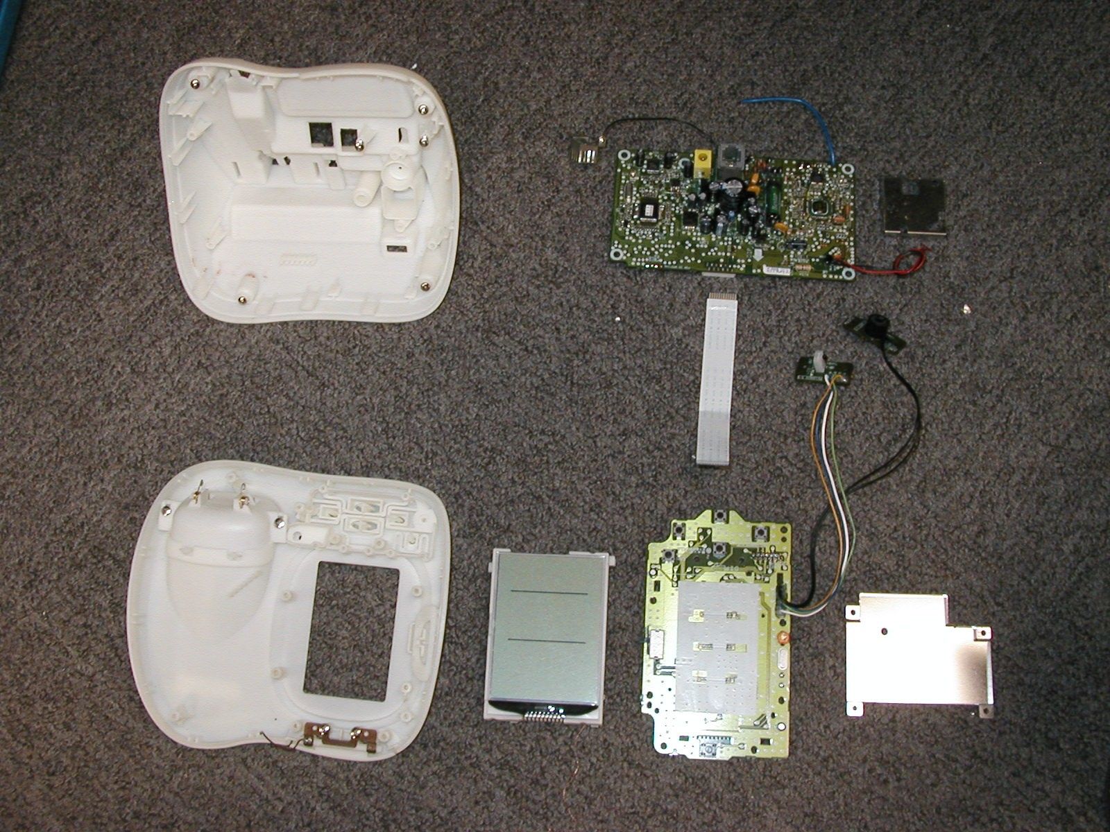
Document Text
Text extracted from the exhibit documents filed with the FCC. Open a document above to read the original.
Users Manual
EWCI 936 [1] www.uniden.com Contents Welcome/Features 2 Controls and Functions 3 Terms Used in this Manual 5 Getting Started Installing the Phone and Outdoor Sensor 6 A. Choose the Best Location (Base and Handset) 6 B. Install the Rechargeable Battery Pack into the Handset 8C. Connect the Base, Set up the Outdoor sensor and Charge the Handset 9 D. Wall Mounting the Outdoor sensor 11 E. Mount the Base Unit on a Wall 12 Weather Menu Options 14 Set the Alarm Clock 17 Basic Phone Setup 19 Programming Memory Locations/Caller ID/Speed Dialing 23Storing Names and Numbers in Speed Dial Memory 23 Storing Caller ID Messages in Speed Memory Locations 26 Caller ID and CIDCW (Caller ID on Call Waiting) 27 When the Telephone Rings 27 Viewing the Caller ID Message List 28 Deleting Information from the Caller ID List 29 Using Your EWC1936 Using the Weather Station 30 Reading the Weather Display at the Base 30 Reading the Weather Data from the Handset 35 Making Calls from Speed Dial Memory 35 Using Your Phone 36 Making and Receiving Calls 36 Making Calls from Speed Dial Memory 37 Making a Call from the Caller ID List 38 Adjusting the Earpiece Volume 38 Using a Headset 39 Headset installation 39 Making calls with the headset 39 Receiving calls with the headset 40 Installing the Beltclip 40 Tone Dialing Switch-over 41 Traveling Out-of-Range 41 Selecting a Different Channel 41 Finding a Lost Handset 42 Using Call Waiting 42 Voice Mail Waiting Indicator 43 Additional Information Changing the Digital Security Code 44 Note on Power Sources 45 General Information 48 Troubleshooting 49 Liquid Damage 52 Precautions & Warranty 53 I.C. Notice 55 TERMINAL EQUIPMENT 55 RADIO EQUIPMENT 55 Index 56Memory List 57 CH04_Contents.fm Page 1 Wednesday, June 2, 2004 6:04 PM WELCOME/FEATURES [ 2 ] www.uniden.com As an Energy Star £ Partner, Uniden has determined that this product or product models meets the Energy Star £ guidelines for energy efficiency. Energy Star £ is a U.S. registered mark. WelcomeFeatures • 900MHz Extended Range Technology• Weather Forecast Display at both Handset & Base • Weather Forecast Display (Barometric Variation, Moon Phase, Tide Level, Tem-perature, Indoor and Outdoor Humidity) • Time & Calendar Display•Alarm with Snooze Feature• Backlight and LCD Contrast Control• 3 Line Backlit Display• Caller ID and Caller ID on Call Waiting • 10 Number Memory Dialing• Last Number Redial• Voice Mail Waiting Indicator• English, French or Spanish Support• Pulse/Tone Dialing•Find Handset Locator• Earpiece Volume Control•Ringer Volume Control• Hearing Aid Compatible• 17 Channel Autoscan Be sure to visit our web site: www.uniden.comUniden® is registered trademark of Uniden America Corporation.AutoTalk, AutoStandby, UltraClear Plus, Random Code, and AutoSecure are trademarks of Uniden America Corporation. Congratulations on your purchase of the Uniden cordless telephone. This phone is designed and engineered to exacting standards for reliability, long life, and outstanding performance.Note:Illustrations in this manual are used for explanation purposes. Some illustrations in this manual may differ from the actual unit. The color of your cordless phone may vary. WELCOME/FEATURES UP033BH_EXI7246C.book Page 2 Wednesday, June 2, 2004 1:30 PM [3] CONTROLS & FUNCTIONS www.uniden.com Controls and Functions 56879 1011 1 342 1213151416171819 CONTROLS & FUNCTIONS 1. Handset antenna2. Jack for optional headset3. Beltclip hole4. Handset battery compartment5. Handset earpiece6. LCD display7. / /vol/ (earpiece volume, ringer volume and scroll) key (pages 19, 22 and 38) 8. call id/menu key (pages 19 and 28)9. * /tone/ m key (left cursor) key (pages 24 and 41) 10. redial/pause key (pages 25 and 37)11. select key (page 19)12. talk/flash key (pages 35 and 42)13. end key (pages 36 and 38)14. key (page 35) 15. #/ o (right cursor) key (page 24) 16. mem key (page 23)17. delete/channel key (pages 24, 29 and 41)18. Handset microphone and ringer speaker19. Handset charging contacts Handset CH06_Controls.fm Page 3 Wednesday, June 2, 2004 6:05 PM CONTROLS & FUNCTIONS [ 4 ] www.uniden.com 31 32 33 2021 26 27 29 30 22232425 28 CONTROLS & FUNCTIONS 20. Base charging contacts21. charge/in use and VMWI (Voice Mail Waiting Indicator) LED 22. Snooze button (page 18)23. LCD display24. alarm switch (page 17)25. find handset key (pages 42 and 44)26. select key (page 14)27. or key (page 14, page 17) 28. enter key (page 14)29. DC IN 9V jack30. Telephone line jack (Inside the outside unit compartment) 31. Channel switch (page 10)32. Check Battery button33. battery check LED BaseOutside unit UP033BH_EXI7246C.book Page 4 Wednesday, June 2, 2004 1:30 PM [5] TERMS USED IN THIS MANUAL www.uniden.com Terms Used in this Manual • Standby Mode - The handset may be sitting in or off the base, but is NOT in use. The talk/flash key has not been pressed and there is no dial tone. • Talk Mode - The handset is off the base and the talk/flash key has been pressed, enabling a dial tone. • CID - Caller ID • CIDCW - Caller ID on Call Waiting • Outdoor sensor - The outdoor sensor senses the temperature and humidity and sends the received data to the base. TERMS USED IN THIS MANUAL UP033BH_EXI7246C.book Page 5 Wednesday, June 2, 2004 1:30 PM GETTING STARTED [6] www.uniden.comInstalling the Phone and Outdoor Sensor Do the following steps:A. Choose the Best Location (Base and Handset)B. Install the Rechargeable Battery Pack into the HandsetC. Connect the Base, Set up the Outdoor sensor and Charge the HandsetD. Wall Mounting the Outdoor sensorE. Mount the Base Unit on a WallA. Choose the Best Location (Base and Handset)When choosing a location for your new phone, here are some important guidelines you should consider: Avo id h eat sources, suc h as ra di ators, air ducts, and sunlight Avoid television sets and other electronic equipment Choose a central location Avo id no i se sources suc h as a w i n d ow b y a street with heavy traffic Avoid microwave ovensAvoid excessive moistu…
Text truncated - open the document above for the full version.
Cover Letter(s)
REQUEST FOR CONFIDENTIALITY June 10, 2004 To: Federal Communications Commission Equipment Authorization Branch Laboratory Division Office of Engineering and Technology 7435 Oakland Mills Road Columbia, Maryland 21046 Subject: Data for FCC Certification Applicant: Uniden America Corporation 181 N. Country Club Road, P.O. Box 580 Lake City, South Carolina 29560 James R. Haynes, Vice President, Engineering and Regulatory Affairs TYPE OF EQUIPMENT: Cordless Telephone System with Weather Sensor Indicator FCC IDENTIFIER: AMWUC354EWCI Dear Sir or Madam: Some of the material included in this application contains trade secrets and proprietary information not customarily released to the public. Because public disclosure of the material might be harmful to the applicant and provide unjustified benefits to its competitors, it is requested that the following be withheld from public disclosure: Circuit Description Schematic Diagrams Block Diagrams Trade secrets and proprietary information can be held confidential. Therefore, we wish to invoke the act under the provisions of 47CFR, Sections 0.457(d) and 0.459. Please contact the undersigned if you have any questions or need any further information. Regards, James R. Haynes Vice President, Engineering and Regulatory Affairs
ID Label/Location Info
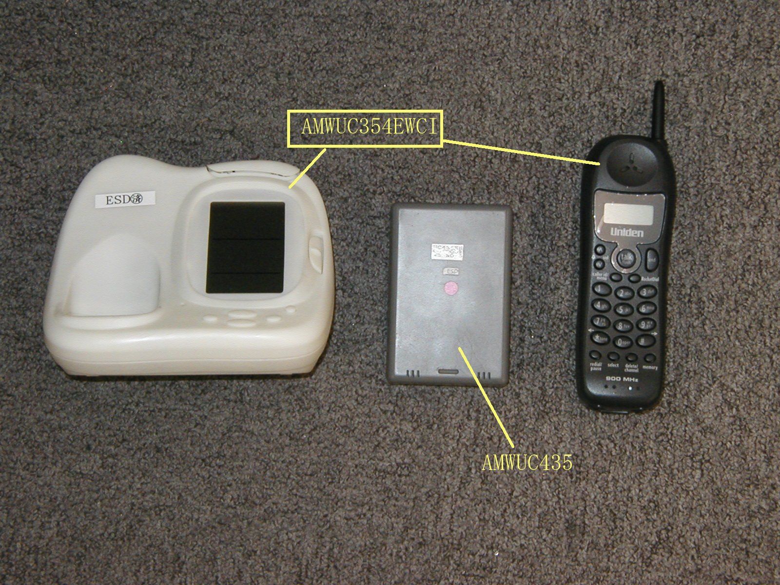
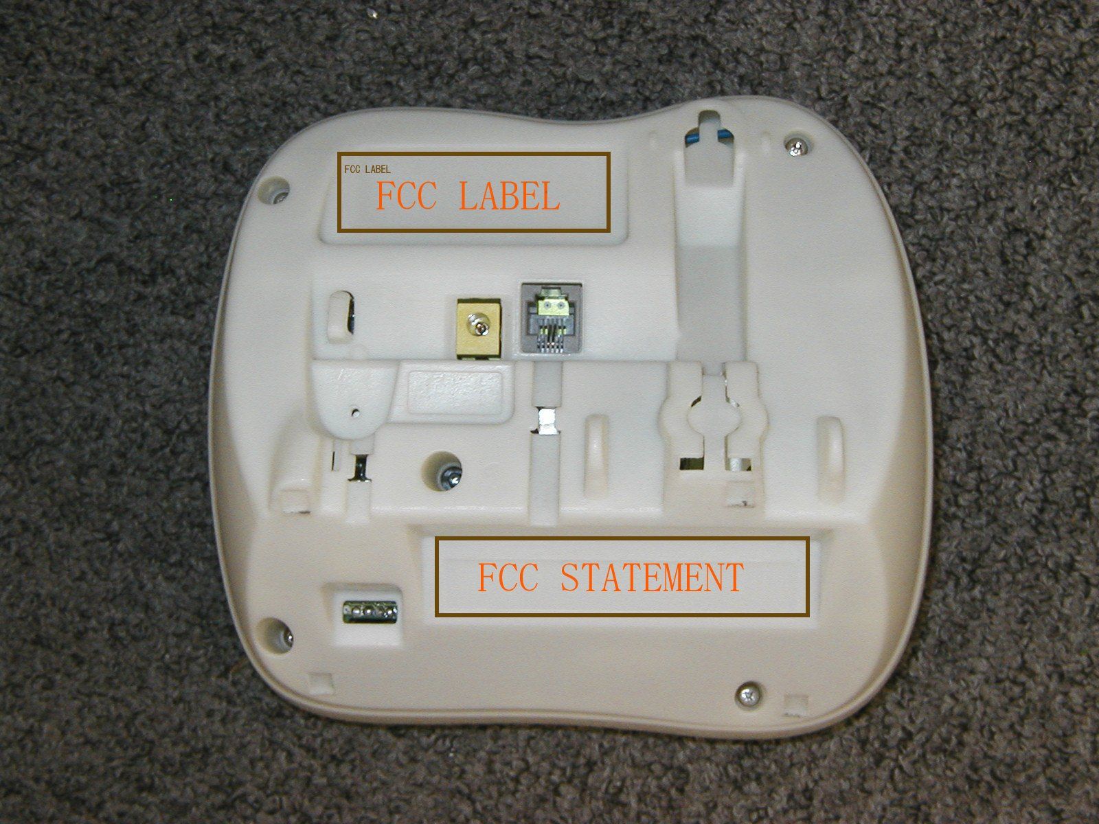
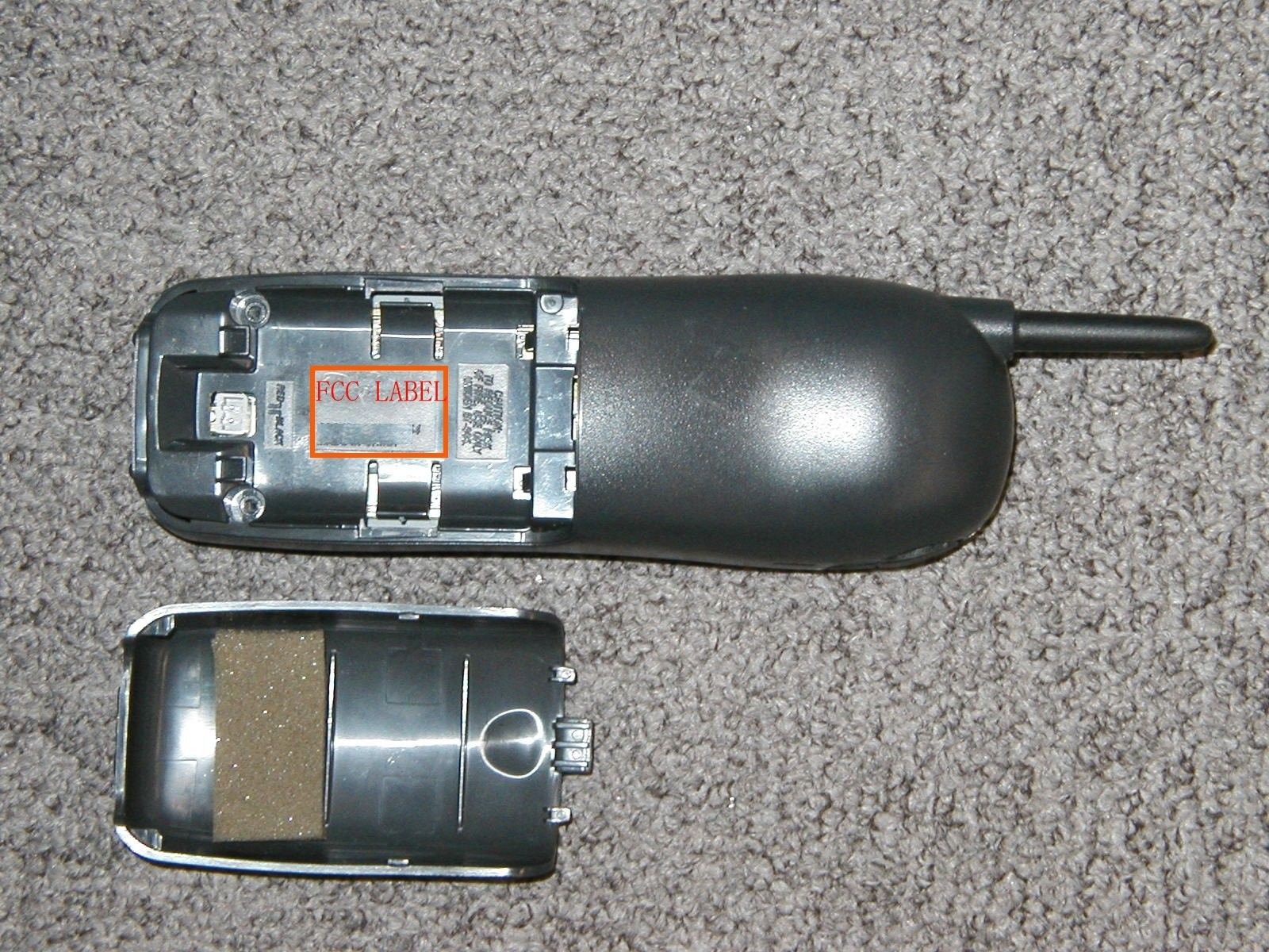
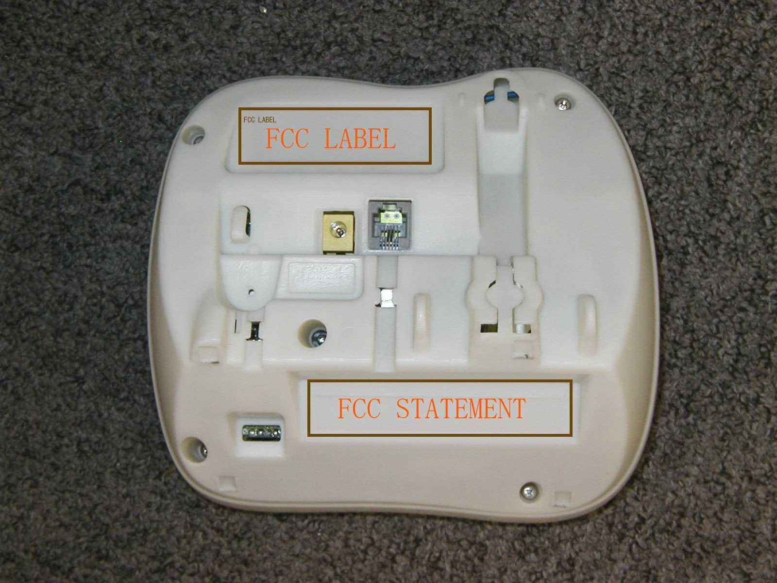
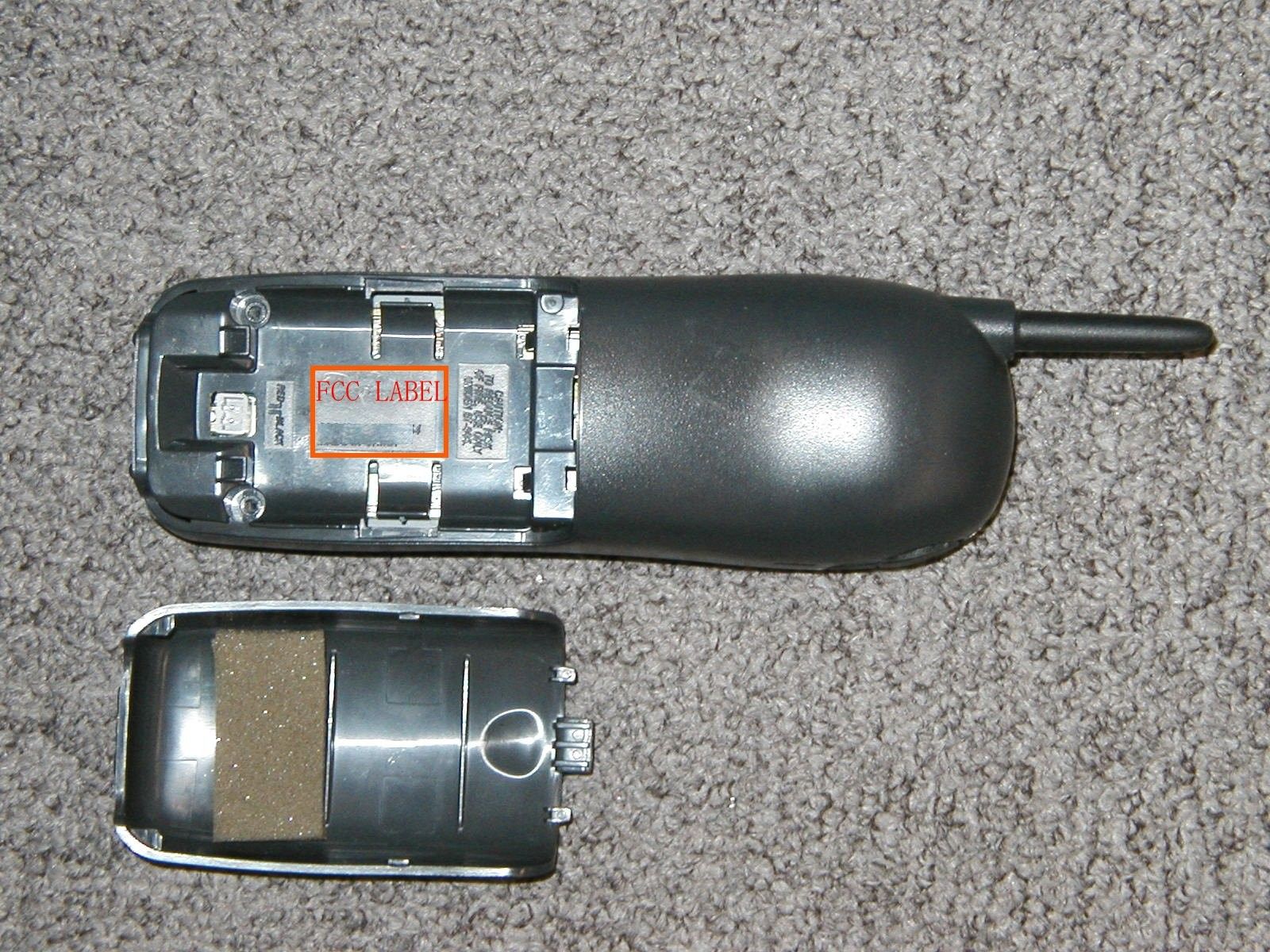
Equipment Identification Label Equipment Label: The following labels are permanently affixed to the Base Unit: 1) BASE UNIT: 52 mm (W) X 28 mm (H) 2) BASE UNIT (FCC STATEMENT): 52 mm (W) X 12 mm (H) 3) HANDSET: 30 mm (W) X 20 mm (H)
Operational Description
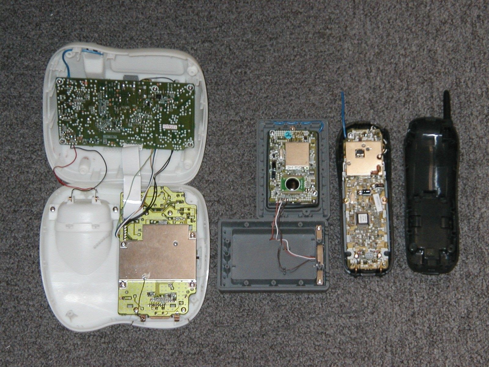
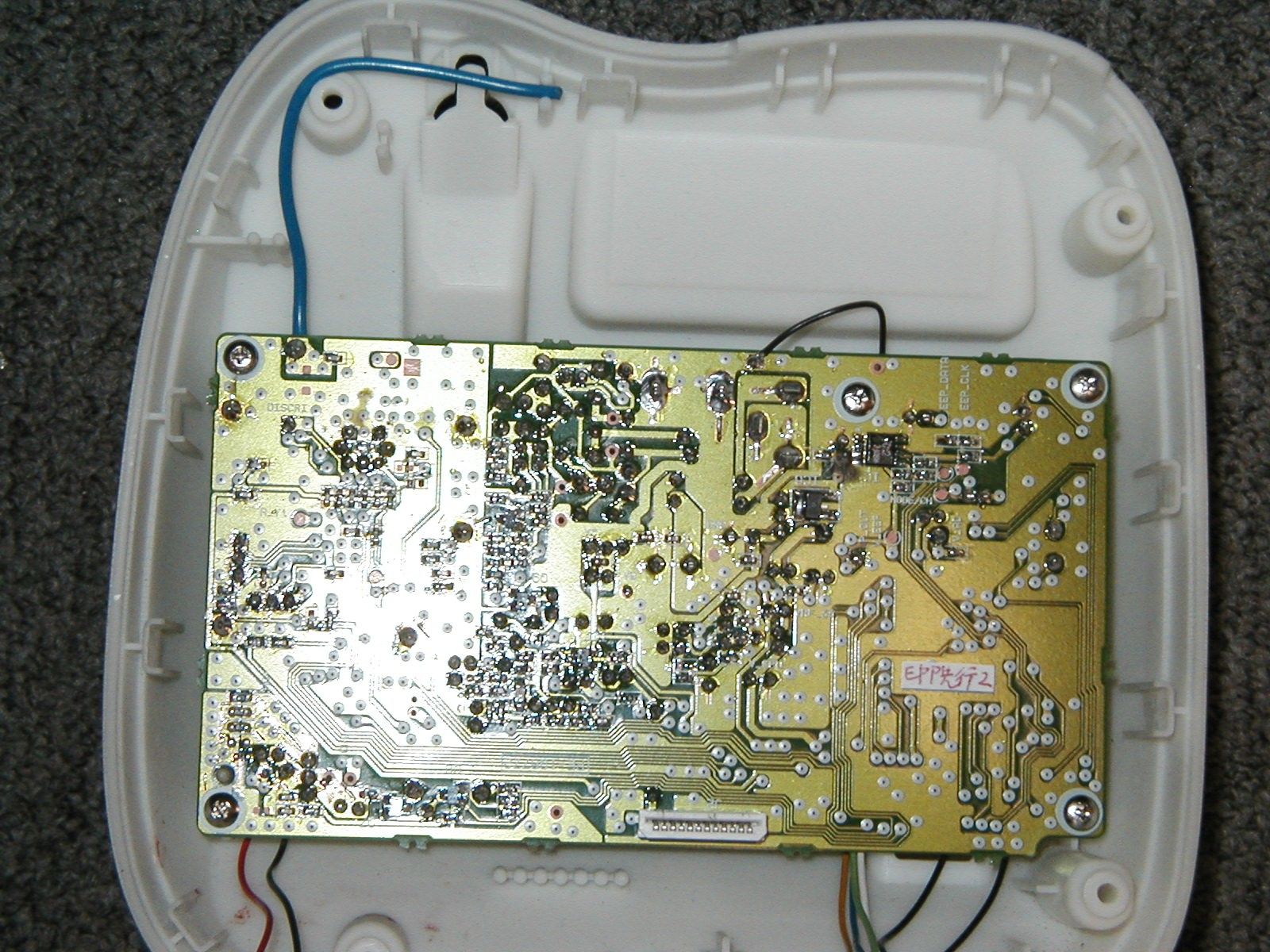
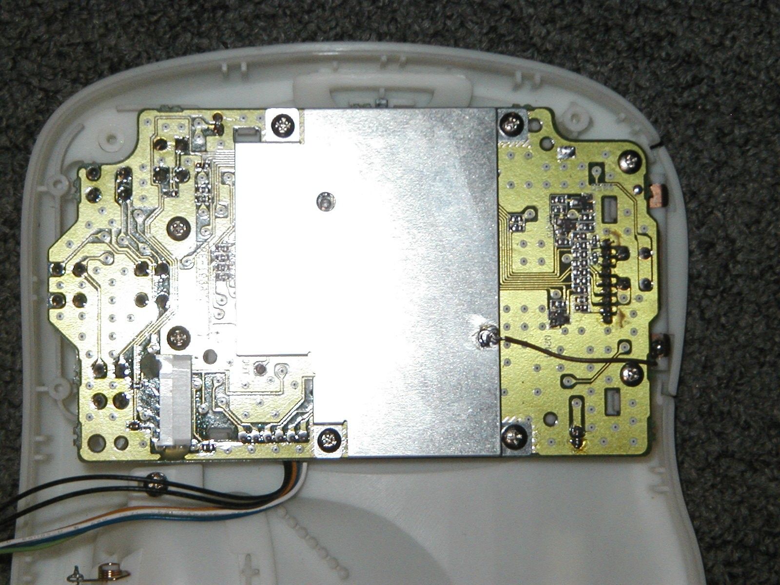
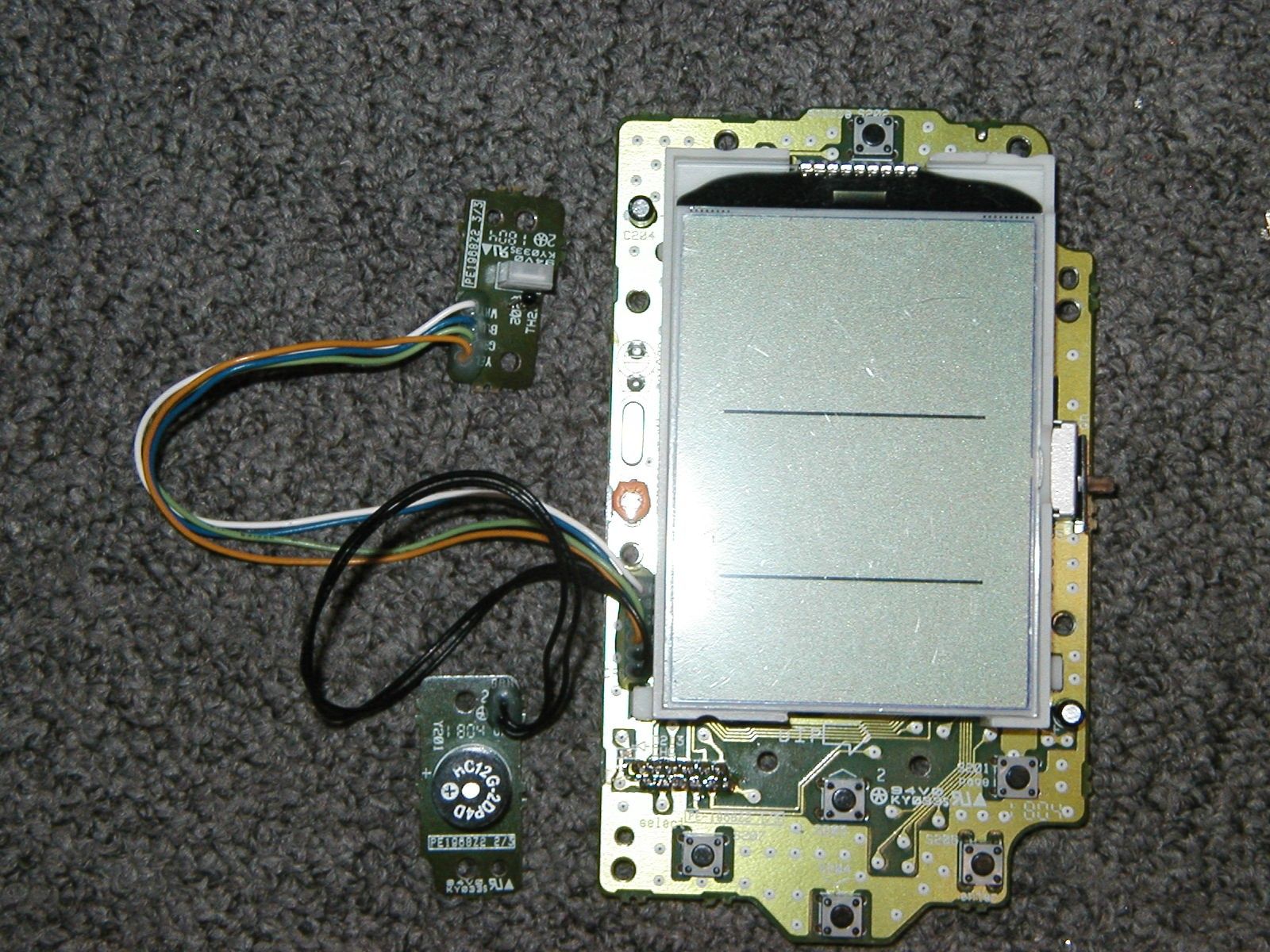
CIRCUIT DESCRIPTION AND DIGITAL SECURITY CODE INFORMATION Equipment Description FCC ID# AMWUC354EWCI ===================== This 900MHz cordless telephone is a telephone terminal device that is designed for voice operation in a similar fashion as an ordinary residential or business telephone without the inconvenience or restraint of a handset cord. This cordless telephone system consists of a base unit and a handset. The base unit is connected to a standard telephone modular jack (USOC Type RJ-11C) and is supplied power from a standard electrical outlet by the use of an AC Adapter. The base unit also has the capability of displaying temperature and humidity information when operating with the associated weather sensor transmitter (FCC ID# AMWUC435). The handset is powered from an internal battery pack that is recharged from the base unit when it is placed into the charging cradle. This device operates by means of a full duplex radio frequency system in 902 - 928 MHz band. The radio frequency system operates in accordance with Part 15 of the FCC Rules. Additionally, this device has been specifically designed to comply with the requirements set forth in Part 68 of the FCC Rules. Circuit Description and Operating Frequency =========================================== Overview This device is a Cordless Telephone System that operates within the 900MHz ISM band. This device consists of a base unit and a handset. The base unit connects to the telephone network, and has transmitter(TX) and receiver(RX) circuits that communicate with the handset. The handset also has a transmitter and receiver in addition to a dialing circuit, earphone, and microphone. Both the handset and the base units incorporate Phased-Locked-Loop (PLL) technology with a Voltage Controlled Oscillator (VCO). Internal circuitry enables communications on an empty channel. Pressing the CH key on the handset will move communications to another open channel while maintaining the telephone line. This feature is used to avoid interference caused by ambient radio noise. 1. Handset 1) Local Oscillator Frequencies and Intermediate Frequencies TX VCO Frequency: 451.122102 MHz - 452.166135 MHz RX 1st Local Freq.: 936.150449 MHz - 938.238517 MHz RX VCO Frequency: 468.075224 MHz - 469.119258 MHz Intermediate Frequency: 10.539771 MHz 2) Communication Link to Base unit RX Circuit: An incoming radio frequency (RF) signal from the base unit is received through the antenna. COMBO IC (IC603)contains among other things,the RX VCO and a doubler circuit. The resultant frequency is known as the RX local oscillator frequency. The local oscillator signal is applied to Mixer (IC603) that produces the intermediate frequency (IF) of 10.539771MHz. The demodulated audio frequency (AF) signal is amplified by IC603, which contains an internal audio amplifier that drives the speaker. TX Circuit: TX reference signal is generated within the PLL circuit, the TX VCO (IC603), and doubler circuit (IC603). Meanwhile, voice signal from the microphone (MC601) modulates the TX reference signal at IC603. This modulated RF signal is the TX RF frequency that is listed in frequency chart. The TX RF signal is then amplified by RF AMP (IC603) and fed into the antenna through a band pass filter (FL601). 3) Dialing Signal When cordless telephone is in Talk Mode, the transmitting circuit and dialing circuit are activated to make outgoing telephone calls. In this condition, when the number keys are depressed, the CPU (IC601) generates corresponding dial pulse codes. 4) Receiving Weather Data from Base When the WX key is depressed, handset is connected to base unit for getting weather data from base unit. The handset then indicates weather data on the handset’s Liquid Crystal Display (LCD)(DP601). 2. Base Unit 1) Local Oscillator Frequencies and Intermediate Frequencies TX VCO Frequency: 462.805339 MHz - 463.849373 MHz RX 1st Local Freq.: 891.704432 MHz - 893.792500 MHz RX VCO Frequency: 445.852216 MHz - 446.896250 MHz Intermediate Frequency: 10.539771 MHz 2) Communication Link to Handset RX Circuit: An incoming RF signal from the handset is received through the antenna. COMBO IC (MY511), which contain the RX VCO and the doubler circuit, along with the resonance inductors (L1, L2) produce the RX local oscillator frequency. The local oscillator frequency is applied to Mixer (MY511) that produces the RX IF of 10.539771MHz. The demodulated signal of MY511 contains a security code, and the code is fed to the CPU (IC3). TX Circuit: TX reference frequency is generated by the PLL circuit and the TX VCO (MY511), resonance inductor (L12, L13) and doubler circuit (MY511). Meanwhile, the voice signal from the telephone network modulates the TX reference frequency at MY511. This modulated signal is the TX RF frequencies as listed in frequency chart. The TX RF signal is then amplified by RF AMP (MY511) and fed into the antenna through a band pass filter (FL1). 3) Dialing Signal Dial pulse code sent from the handset is demodulated by MY511 as mentioned before, and is fed into the CPU (IC3) to control the Hook Relay, RL1. 4) Power Supply Circuit The power supply circuits are composed of IC6, IC7, IC10, and IC11. These are voltage regulator integrated circuits (IC) to stabilize the input voltage from the AC Adapter to attain a stable operation. 5) Receiving weather data from the associated sensor (FCC ID# AMWUC435) During the absence of a telephone communication link between the base unit and handset, the base unit has the ability of showing temperature, humidity and pressure change information. For receiving outdoor temperature and humidity information that is generated by the associated sensor (FCC ID# AMWUC435), the base unit will be able to receive either one of CH1, CH10 and CH20 on the 900MHz ISM band frequency table. When WX key on the base unit is pressed, the base unit will transmit weather data to handset. Digital Security Code Information ================================= a) For Base and…
Text truncated - open the document above for the full version.
Test Report
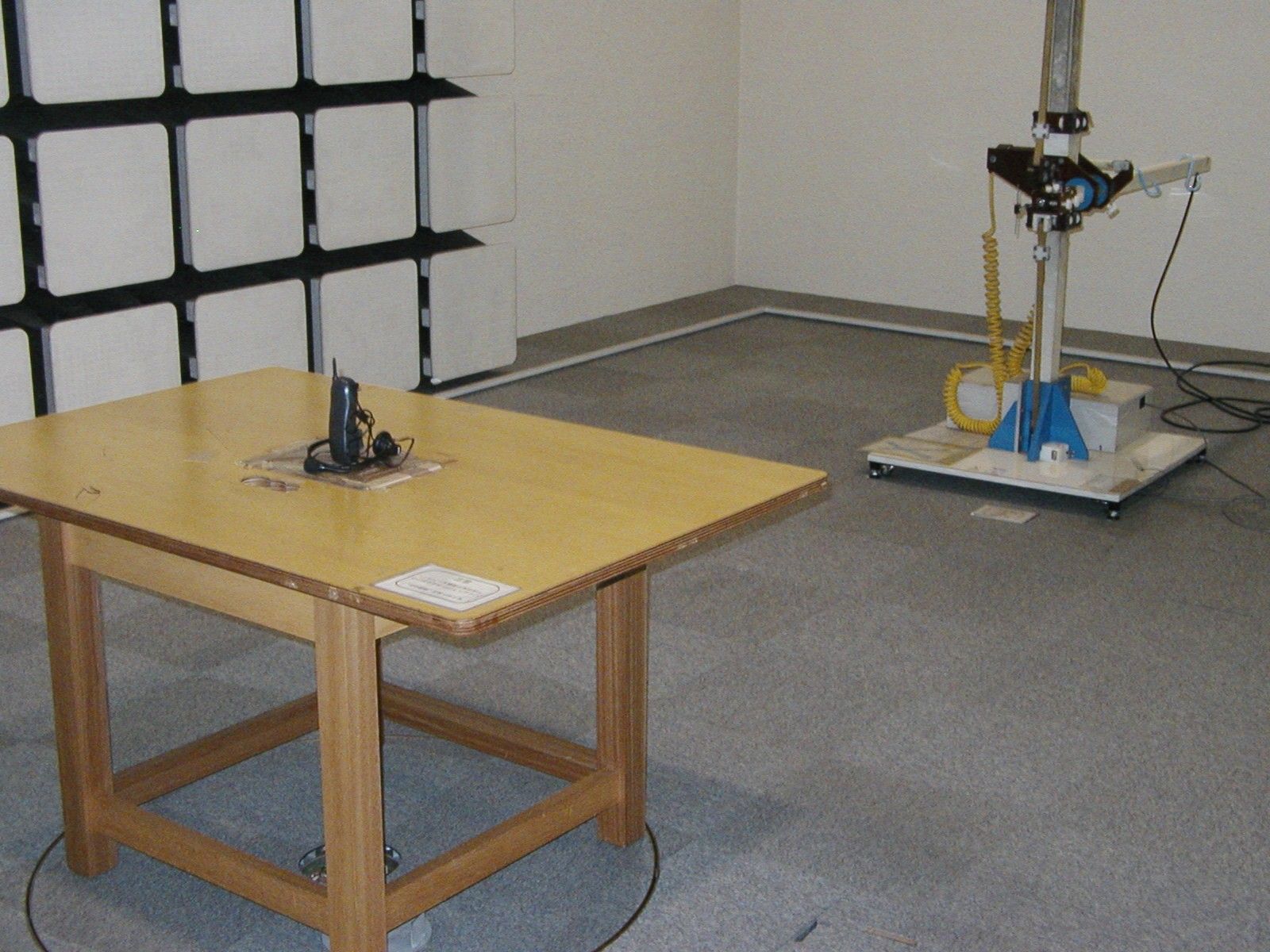
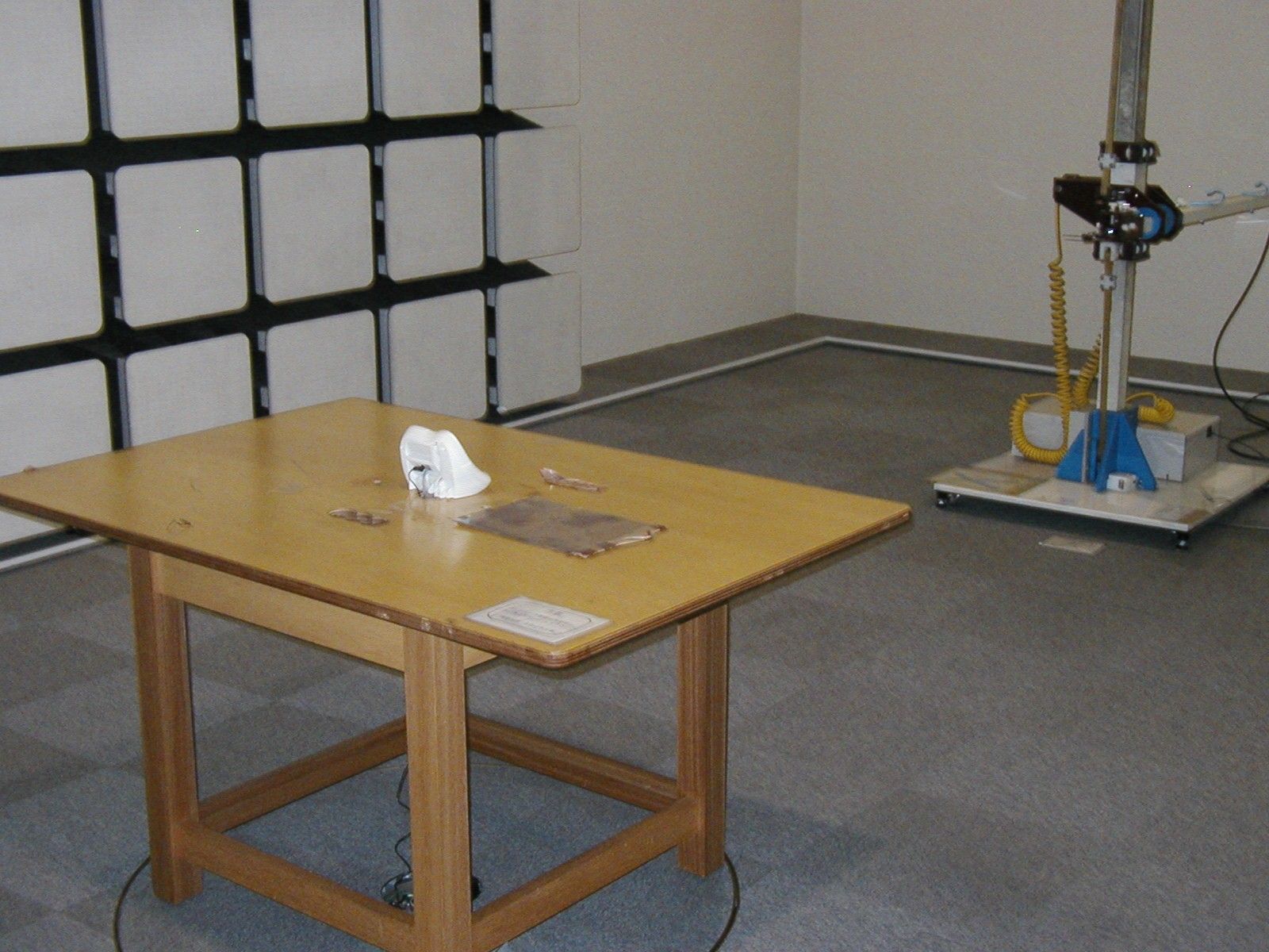
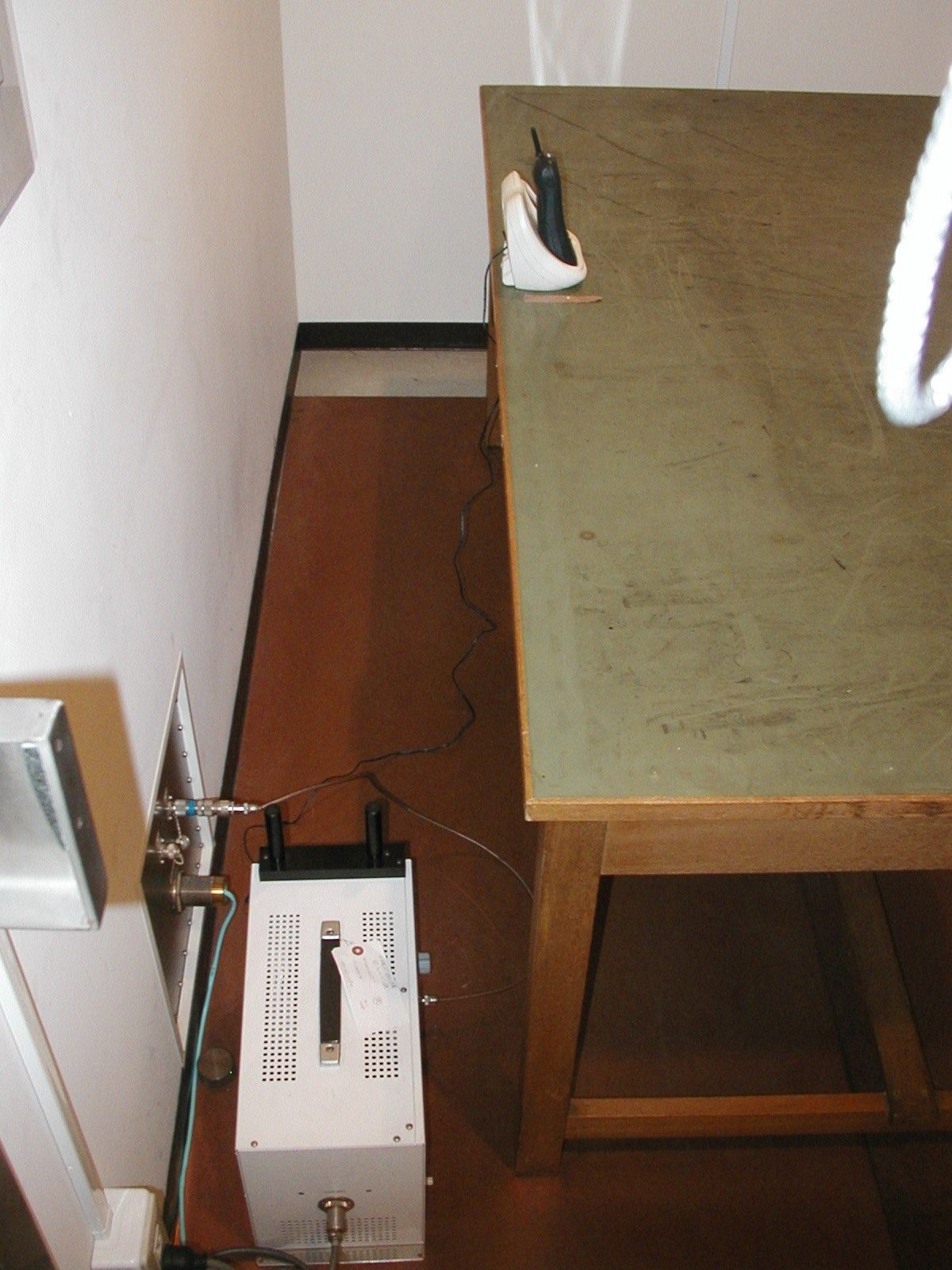
Test Report TEST PROCEDURES AND TEST SITE DESCRIPTION DATE: May 31, 2004 Tested by: Uniden Corporation (Japan) MEASUREMENT ITEMS Section No. 5-1 Field Strength of Radiated Emissions 15.249(a)(b) 15.205 / 15.209 5-2 Power Line Conducted Emissions 15.207 SUPPLEMENT DATA - BAND EDGE EMISSIONS 5-1 Field Strength of Radiated Emissions 15.249(a)(b) 15.205 / 15.209 The measurements were performed in accordance with the ANSI C63.4- 1992. Field Strength measurements of radiated spurious emissions were made at the open test site of a 3 meter range maintained by Uniden Corporation in Japan. Complete description and measurement data of this test site have been placed on file with the Commission. The radio frequency spectrum was scanned in the range of 30 MHz to 10 GHz in accordance with the section 15.33(a) of the FCC Rules. The frequency below 1 GHz, the measurement was carried out by using CISPR quasi-peak detector, AGILENT E7404A the Spectrum Analyzer in accordance with the sections 15.33(a) and 15.35(a). The frequency above 1 GHz, the measurement was also carried out by using the E7404A Spectrum Analyzer in accordance with the section 15.35(b). A bilog antenna CBL6112A was used to cover the range from 30 MHz to 1000 MHz. Narrowband tuned dipole antennas were used over the entire 30 to 1000 MHz range for precision measurements of field strength. Above 1000 MHz, a horn antenna EMCO 3115 was used. For each spurious or harmonic frequency, the antenna was raised and lowered to obtain a maximum reading on the Spectrum Analyzer with antenna horizontally polarized. Then the turntable, on which the equipment under test was placed, was rotated a minimum of 360 degrees to further increase the reading on the Spectrum Analyzer. This procedure was repeated with the antenna vertically polarized. The equipment under test was placed in its normal operating position on a turntable approximately 0.8 meter in height. In order to convert the measured emission levels into field strength in dBuV/m, the actual field strength (Ef) is determined by algebraically adding the measured emission level (Em) and the antenna correction factor (ACF) including the cable loss at the appropriate frequency. Ef [dBuV/m] = Em [dBuV/m] + ACF [dB] FCC Limits: a) Fundamental emission: 94 dBuV/m (50,000 uV/m) b) Spurious emissions: 30 - 88 MHz 40 dBuV/m (100 uV/m) 88 - 216 MHz 43.5 dBuV/m (150 uV/m) 216 - 960 MHz 46 dBuV/m (200 uV/m) Above 960 MHz 54 dBuV/m (500 uV/m) Test Results: Refer to the attached test reports. All emissions not reported were more than 20 dB below the limits. NOTE: For measurement of the handset, all of the testing were made with the internal battery that is fully charged. For measurement of base unit, all of the testing were made with the AC Adapter which connected to a standard voltage source. 5-2 Power Line Conducted Emissions 15.207 Test Procedure: The measurements were performed in accordance with the ANSI C63.4- 1992. During the measurements, a standard voltage source is fed into the unit under test through a power line impedance stabilization network. FCC Limit: The radio frequency voltage that is conducted back into the AC power line on any frequencies within the band from 150kHz to 30MHz shall not exceed the following limitation. REQUIREMENTS: FREQUENCY(MHz) LEVEL (dBuV) 0.150-0.50 66 to 56 QP 56 to 46 Ave 0.50-5.0 56 QP 46 Ave 5.0-30.0 60 QP 50 Ave Test Results: Refer to the attached test reports. All emissions not reported were more than 20 dB below the limits. NOTE: Regarding the Handset, this FCC requirement is not applicable to it since the Handset is intended to use the battery only. SUPPLEMENT DATA - BAND EDGE EMISSION Attached data show the handset’s transmission on lowest channel and base unit’s transmission on highest channel. At the outside of emission bands, those emissions are well reduced against the operational channel frequency of the units. TEST CONDITIONS: Modulation : 1000 Hz
Contact Information
Applicant
Paul Roby
Test Firm
Uniden CorporationKeizo Fujiwara
Technical Specifications
| # | Rule Parts | Frequency Range | Power Output | Emission |
|---|---|---|---|---|
| 2 | 15C | 925.610677 MHz - 927.698745 MHz | - | F3E |
Other Applications from Uniden America Corporation
AMWUA2405
Apr 15, 2026RADAR DETECTOR
Equipment Class
JBP - Part 15 Class B Computing Device PeripheralAMWUA2406
Apr 15, 2026RADAR DETECTOR
Equipment Class
JBP - Part 15 Class B Computing Device PeripheralAMWUA2402
Jul 23, 2024RADAR DETECTOR
Equipment Class
CRD - Part 15 Radar Detector
AMWUA2404
Feb 17, 2024Wi-Fi Bluetooth Combo Module
Equipment Class
DTS - Digital Transmission System
AMWUA2301
Feb 15, 2023RADAR DETECTOR
Equipment Class
CRD - Part 15 Radar Detector