AMWUH045Portable Cellular Telephone
Uniden America Corporation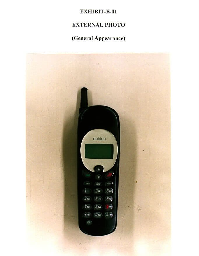
Click to zoom
Application Details
- Equipment Class
- TNE - Licensed Non-Broadcast Transmitter Held to Ear
- Date of Grant
- Aug 23, 1998
- Application Purpose
- Original Equipment
- Date of Application
- Jun 01, 1998
- Equipment Note
- Portable Cellular Telephone
- Frequency Range
- 824.00000000 - 849.00000000
- Company
- Uniden America Corporation
- Country
- United States
Documents & Files
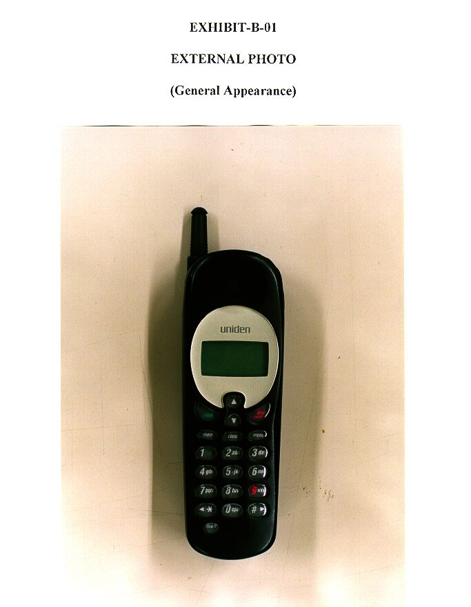
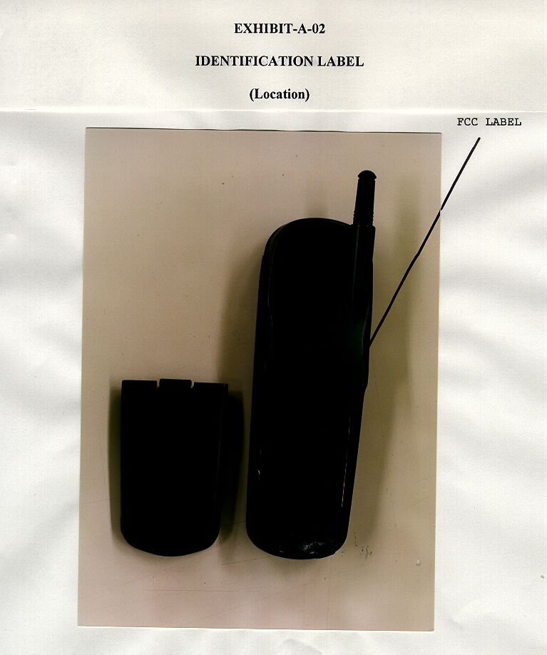
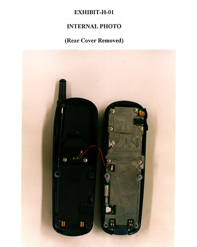
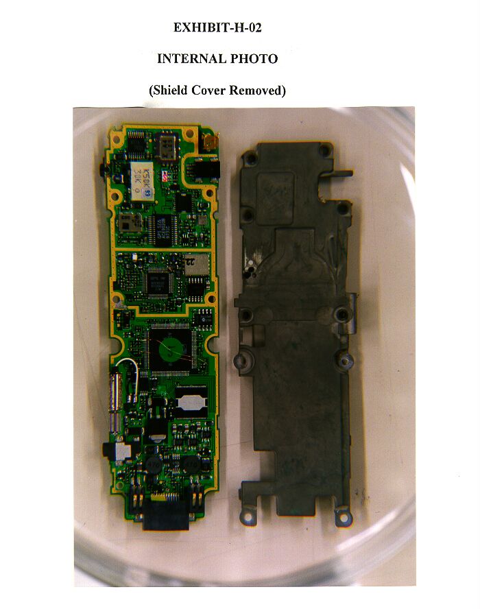
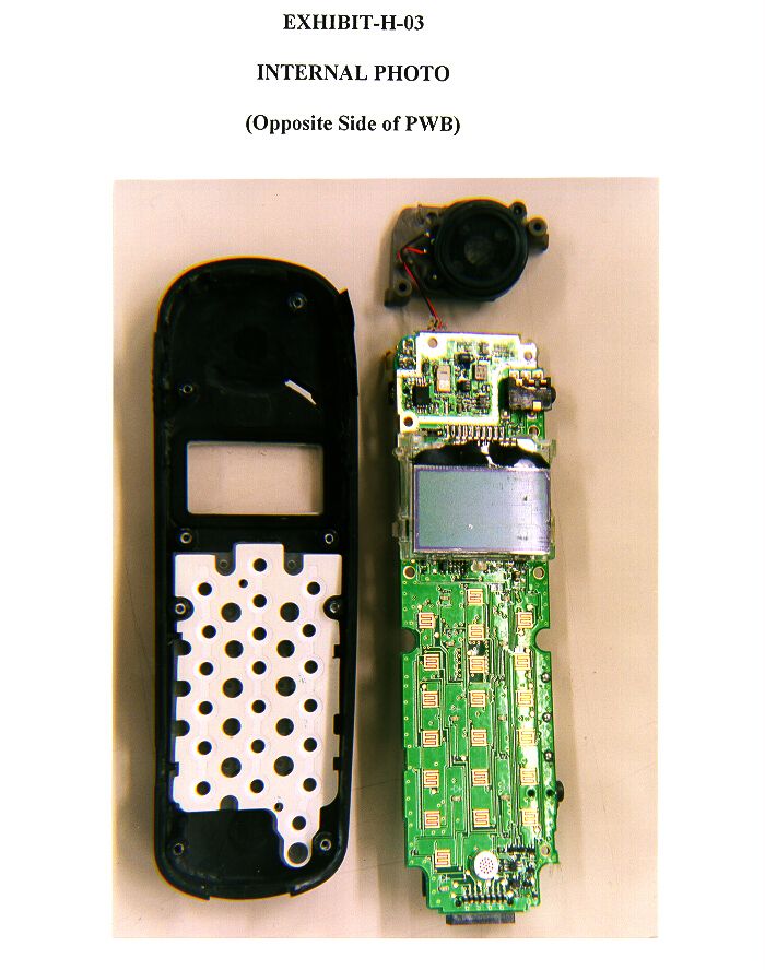
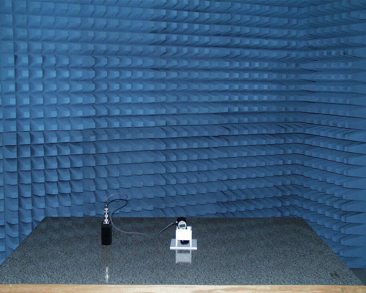
Document Text
Text extracted from the exhibit documents filed with the FCC. Open a document above to read the original.
Users Manual
Precautions! Before you read anything else, please observe the following: Warning! Uniden America CorporationDOES NOTrepresent this unit to be waterproof. To reduce the risk of fire, electrical shock, or damage to the unit,DO NOTexpose this unit to rain or moisture. Important! Read this section before using your wireless phone. This wireless phone is a radio transmitter and receiver. When the phone is on, the antenna is the part of the phone that sends out and receives radio frequency (RF) energy in the 824 to 894 MHz range using common frequency modulation (FM) techniques. When you use your phone, the wireless system handling your call controls the power level (usually 0.006 watts to 3 watts) at which your phone transmits. In 1991, the institute of Electrical and Electronics Engineers (IEEE), and in 1992 the American National Standards Institute (ANSI) updated the 1982 ANSI Standard for safety levels with respect to human exposure to RF energy. Over 120 scientists, engineers, and physicians from universities, government health agencies, and industry, after reviewing the available body of research, developed this updated Standard. In March, 1993, the Federal Communication Commission (FCC) proposed the adoption of this updated Standard. For the safe and efficient operation of your phone, observe these guidelines: 1.Warning: Uniden Multimedia Corporationdoes not represent this unit to have beenwaterproofed. To reduce the risk of electrical shock, fire hazard, or damage to the unit, do not expose to rain or moisture. 2. Do not operate this wireless phone when holding the antenna, or when any person is within 4 inches of the antenna. To limit RF exposure, control the duration of your calls. 3. Do not use the phone with a damaged antenna. If a damaged antenna comes into contact with the skin, a minor burn may result. If the antenna is damaged, replace it with a Uniden-approved antenna before operating the phone. Contact your Uniden dealer for more information. 4. When using your phone while driving, Uniden recommends that you only use the phone when the vehicle is stationary. This ensures that you maintain full attention to driving while the vehicle is in motion. You are responsible for driving safely and using reasonable judgment while using your wireless phone. 5. RF energy from wireless telephones may affect some personal medical devices (pacemakers, hearing aids, etc.) Consult your physician or the device manufacturer for information regarding the effect of RF energy on personal medical devices. 6. Do not use this wireless phone in an airplane. 7. Do not allow children to play with the phone. It is not a toy. Children could hurt themselves or others (by poking themselves or others in the eye with the antenna, for example). Children could also damage the phone or make calls that increase your telephone bills. 8. Obey the warning signs that require mobile radios to be turned off. This is typically required near construction sites where blasting occurs, and in health care facilities. 9. Turn your phone off when in any area with a potentially explosive atmosphere. These areas include fueling areas such as gas stations, below deck on boats, chemical transfer and storage facilities, and areas where the air contains particles (grain, dust, or metal powders.) The FCC Wants You To Know Changes or modifications to this product not expressly approved by Uniden, or operation of this product in any way other than as detailed by the owner’s manual, could void your authority to operate this product. The equipment cannot be used on public coin phone service provided by the telephone company. Connection to party line service is subject to state tariffs. (Contact the state public utility commission, public service commission or corporation commission for information.) The exclamation point within an equilateral triangle is intended to alert the user to the presence of important operating and maintenance (servicing) instructions in the literature accompanying the appliance. UDZZ--- H:...Precautions wireless.vp Mon Jun 01 15:47:08 1998 Color profile: Disabled Composite Default screen Wireless Telephone Privacy Wireless telephones are radio devices. Communications between the handset and base of your wireless telephone are accomplished by means of radio waves which are broadcast over the open airways. Because of the inherent physical properties of radio waves, your communications can be received by radio receiving devices other than your own wireless telephone unit. Consequently, any communications using your wireless telephone may not be private. Adapter Safety Features If the AC adapter furnished with this phone has a polarized line plug (a plug having one blade wider than the other), this plug will fit into thepower outlet only one way. If you are unable to insert the plug fully into the outlet, try reversing the plug. Do notalter the shape of the blades of the polarized plug! NOTE: If you cannot plug the AC adapter into the outlet, contact someone about replacing the outlet. Plug the AC Adapter into a standard 120 VAC wall outlet. Do not use an outlet controlled by a wall switch. Use only the Uniden AC Adapter supplied with this phone. One Year Limited Warranty Important:Evidence of original purchase is required for warranty service. WARRANTOR: UNIDEN MULTIMEDIA CORPORATION (“Uniden”) ELEMENTS OF WARRANTY: Uniden warrants, for one year, to the original retail owner, this Uniden Product to be free from defects in materials and craftsmanship with only the limitations or exclusions set out below. WARRANTY DURATION: This warranty to the original user shall terminate and be of no further effect 12 months after the date of original retail sale. The warranty is invalid if the Product is (A) damaged or not maintained as reasonable or necessary, (B) modified, altered, or used as part of any conversion kits, subassemblies, or any configurations not sold by Uniden, (C) improperly installed, (D) serviced or repaired …
Text truncated - open the document above for the full version.
Users Manual
Keys and Display MINICEL KEYS AND DISPLAY
Users Manual
GLOSSARY A/B switchingSwitch between carriers. Refer to page 31. Any-Key AnswerPress any key (other thansort) to answer an incoming call. Refer to page 19. Call TimersKeeps count of the time (hours, minutes and seconds) that you have used the phone. Reset when you want. Can be for one call, totals calls on line 1 and/or line 2. Refer to page 27. EarpieceWhere you hear conversations. Refer to the back page foldout. Emergency 911With the phone on in standby mode (no numbers in the display), press and holdfor one second. Refer to page 8. GreetingThe first message that appears when your phone is turned on. Refertopage21. KeyguardDisables the keypad until there is an incoming call. Refer to page 22. KeypadThe number keys (0 through 9). Refer to the back page foldout. Minute MinderDuring your conversation, alerts you (through the earpiece) five seconds before each minute is over. You can set the volume or enable/disable the feature. Refer to page 17. Monitor”On hook dialing” - You hear the conversation from the speaker on the back instead of from the earpiece. Since the microphone (on the front) is disabled during monitor, the caller can’t hear you. This feature is great for calling a bank or similar automated answering system. Refer to page 9. MuteDisables/enables the (mouthpiece) microphone during a conversation. Refer to page 9. RoamWith the roam feature, use your unit when you are out of the home service area. When your cellular phone is “roaming,” ROAMappears in the display. Refer to the back page foldout. ScratchpadTemporary location for a phone number. Refer to page 9. SpeakerOn the back of your phone, it emits sounds and tones. Refer to the back page foldout. PINPersonal Identification Number. Refer to page 26. StandbyReady to send or receive a call. Refer to page 6. 2 9 wxyz C:...Mini200 with cover.vp Thu May 21 16:37:09 1998 Color profile: Disabled Composite Default screen 1 CONTENTS NOTE: Foldout the back cover of this owner’s manual to refer to the “Keys and Display” page. CONTENTS Glossary......................................2 Introduction...................................3 • Welcome...................................3 • Authorization Requirements....................3 • Features....................................3 • Included In Your Package......................4 Setting Up Your Phone...........................5 • Installing the Battery.........................5 • Charging the Battery.........................5 • Battery Low Alarm...........................6 • Antenna....................................6 • Power.....................................6 Calling.......................................7 • Receiving a Call..............................7 Absent Call Counter..........................7 • Making a Call...............................7 Direct Dialing...............................7 Redial From Last 10 Completed Calls.............8 One-Touch Emergency Dialing..................8 PIN Calling.................................8 Inserting a Pause............................8 •Ending a Call................................8 •While Calling................................8 Adjusting the Earpiece Volume..................8 Using the Scratch Pad.........................9 Mute......................................9 Monitor....................................9 Transmitting DTMF Signal(s)...................9 Flash Signal (Signaling Tone)..................9 Memory Programming..........................10 • Storing Numbers and Names..................10 • Checking Memory Status.....................10 • Calling Stored Numbers......................11 Speed Dial.................................11 Super Speed Dial............................11 • Clearing a Memory Location...................11 C:...Mini200 with cover.vp Thu May 21 16:37:10 1998 Color profile: Disabled Composite Default screen 2 Menus - Customizing Your Phone.................12 • The Function Menu Map......................12 Quick Menu Access..........................12 • Sound Menu...............................13 Alert Volume and Tone Menu..................13 Earpiece Volume Menu.......................14 Keypad Volume Menu........................15 Speaker Volume Menu........................16 Minute Minder Menu.........................17 • Phone Settings Menu........................18 Vibrate Menu...............................18 Answer Option Menu........................19 Light Menu................................20 Change Greeting Menu.......................21 Enable Keyguard Menu.......................22 Headset Menu..............................23 Contrast Menu..............................24 • Security Menu..............................25 Change Password Menu......................25 PIN Calling Menu...........................26 •Call Timers Menu...........................27 Current Call Menu...........................27 Show Last Call Time Menu....................28 All Calls Menu..............................29 •Service Settings Menu........................30 Phone Line Menu...........................30 Network Menu..............................31 Specifications.................................32 Optional Accessories............................33 Keys and Display...................inside back cover C:...Mini200 with cover.vp Thu May 21 16:37:11 1998 Color profile: Disabled Composite Default screen
Users Manual
IntroductionINTRODUCTION WELCOME Congratulations on your purchase of the Uniden MiniCel cellular phone. You have chosen to enter the world of cellular telephone technology with one of the finest portable cellular phones available today. Now you can place or receive calls from anywhere there is cellular coverage. Your MiniCel can go with you anywhere so that you’re never out of touch – in your car, on the beach, at the golf course or even just for a walk in the woods. With the roam feature, you can use your phone when you travel away from your own area. The many standard features on the MiniCel make calling quick and convenient. The easy-to-use menu functions help you customize your MiniCel. We’re confident you will be proud to own the MiniCel. To make sure you understand all its convenient features, please take the time to read this owner’s manual. It will help you use the technology and convenience of cellular communications. AUTHORIZATION REQUIREMENTS You must contact your local cellular service company to obtain authorization and a cellular telephone number before using your MiniCel. Fees for cellular service vary from company to company. FEATURES • 50 Memory Locations • 128K Bytes Flash Memory • Any Key Answer • One-Touch Emergency Dial • Speed Redial and Super Speed Redial • Programmable 20-Character Greeting • Password Protection Auto PIN • Battery Alarm • Two-Line, 20 Character LCD Display • Scratch Pad Memory • Speaker and Ringer Volume Control • Keyguard • Call Timers • Tone or Vibrate Alert 3 TO YOUR NEW MINICEL PHONE INTRODUCTION INTRODUCTION C:...Mini200 with cover.vp Thu May 21 16:41:07 1998 Color profile: Disabled Composite Default screen INCLUDED IN YOUR PACKAGE • This Owner’s Manual • Precautions and Important Safety Instructions • Registration Card 4 TIP To get the most from your phone, please read this owner’s manual thoroughly. Also, be sure to complete and mail the product registration form. WARNING If any of these items are missing or damaged, immediately contact your place of purchase. Mini 200AC Adapter and Charger Rechargeable Battery (one of the following:) 580 mAH nickel metal (MC580N) 580 mAH Lithium-ion (MC580L) C:...Mini200 with cover.vp Thu May 21 16:41:09 1998 Color profile: Disabled Composite Default screen Setting Up Your PhoneSETTING UP INSTALLING THE BATTERY Your MiniCel comes with either one of the following: 580 mAH nickel metal (MC580N) or 580 mAH Lithium-ion (MC580L). 1) Line up the notches and metal contacts on the bottom of the battery and the base (the back of the MiniCel). Make sure the label side is facing the phone. 2) Gently press the battery top until it clicks into place. CHARGING THE BATTERY 1) Plug the AC adapter cord into the input jack on the side of the phone. 2) Plug the AC adapter into a standard 120 VAC wall outlet. If you turn the phone on while the battery is charging, CHARGINGwill shows in the display. 3) Charge the battery for 3 hours. If the power is on when the battery is fully charged, the display reads: 5 SETTING UP SETTING UP THE BASICS OF YOUR NEW MINICEL Use only the Uniden AC adapter supplied with this phone. DO NOT use an outlet controlled by a wall switch. HINT Before using your phone, fully charge the rechargeable battery pack. We recommend that the battery pack charges for 3 hours. C:...Mini200 with cover.vp Thu May 21 16:41:12 1998 Color profile: Disabled Composite Default screen BATTERY LOW ALARM When the battery is low,RECHARGE BATTERYshows in the LCD display, the battery icon starts flashing, and the battery low warning tone sounds. ANTENNA Before placing or receiving a call, gently pull the antenna up until it clicks into place. POWER tPower On Press and hold the end on/off key until you hear a tone and see the opening greeting. Then the standby display shows: The MiniCel is now in standby mode. t Power Off Press and hold the end on/off key and the display goes blank. 6 CAUTION Do not touch the antenna while you are using the phone. TIP For the best reception, extend the antenna before using the phone. Do not use the phone with a damaged antenna. Use only the supplied or approved antenna. Unauthorized antennas, attachments or modifications could damage the phone, degrade the quality of the call and violate FCC regulations. WARNING C:...Mini200 with cover.vp Thu May 21 16:41:15 1998 Color profile: Disabled Composite Default screen CallingCALLING RECEIVING A CALL 1) When someone calls your MiniCel, the LCD backlight flashes, the alert sounds (see page ) or vibrates (see page ) and INCOMING CALLappears. 2) If the "any key" feature (page ) is active, press any key other thansort. If you have disabled the "any key" feature, press send. 3) The backlight stops flashing and theicon appears in the display. 4) When you finish your call, press end. t Absent Call Counter When you don't answer an incoming call, the display shows the number of unanswered call(s). Press any key to erase the message. MAKING A CALL t Direct Dialing 1) Enter the phone number on the keypad. To erase a digit, press clearand reenter the correct number. To erase all the digits, press and holdclear. 2) Press send. Theicon shows in the display while a call is in progress. If the "current call timer" feature is on, the counter starts (see page ). 7 CALLING WITH YOUR MINICEL SPEED DIAL Pressmem, the two-digit memory location number (01-50) and send. Or, pressmem, the one-digit number for 1 through 9, andsend. SUPER SPEED DIAL From the standby display, press and hold the one-digit number (only for locations 1through8). Caution:location 9 is for emergencydialing only. CALLING C:...Mini200 with cover.vp Thu May 21 16:41:19 1998 Color profile: Disabled Composite Default screen t Redial From Last 10 Completed Calls 1) With no digits in the display, press send. You will see the last number dialed. 2) Presssortto scroll through the list. 3) When you find the number that you want to call, press send. t One-Touch Emergency Dialing To call 911, make sure that ther…
Text truncated - open the document above for the full version.
Operational Description
2529 1 FCC ID: AMWUH045 OPERATIONAL / CIRCUIT DESCRIPTION UH045Z(Mini200) Circuit Description The transceiver unit employed the architecture where the receive synthesizer makes the channel selection and a second synthesizer generates a fixed transmit offset. This architecture is implemented using the "Receiver and Transmitter Interface" IC (IC20l) and the "Radio Interface and Twin Synthesizer" IC (IC202). IC201 is a VHF oscillator, up-converter and prescaler. IC202 is a combined radio interface circuit and twin synthesizer. Its radio interface section contains circuits to monitor and control levels such as transmit power, circuits to demodulate the frequency modulated signal to audio, and a frequency multiplier. The synthesizer section has the Main synthesizer used to elect serve channel by generating the 1st local oscillator (LO) frequency. The fixed Auxiliary synthesizer is used for the transmit-receive offset and for modulation. IC202 also generates 8 . 064 MHz system clock for the "System Controller and DATA MODEMU” IC (IC401). 1 RF l.1 RF Receiver Section RF inband signal enters the duplexer (FL101) of the transceiver through the external antenna system. This duplexer has a cutoff frequency of 869 - 894 MHz where emissions outside of this band are well reduced to prevent interference caused by unwanted signals. The received inband signal is then amplified by approximately 10dB by the low noise amplifier (LNA) Q101 to improve its Noise Figure. This LNA also works as buffer circuit to prevent antenna conducted emissions in the antenna circuit. Then this amplified inband signal goes to the SAW bandpass filter which has cutoff frequency of 869 - 894 MHz. This filter further rejects out of band interferences and reduces antenna conducted emissions. After filtering, the signal is mixed with the 1st LO frequency by IC101 to provide the first IF at 45 MHz. At this stage, impedance matching for these signal sources are well achieved to isolate the signals from each other to prevent antenna conducted emissions from going toward the antenna. The 1st LO is generated by the PLL synthesizer circuit which includes the combination oflC201, IC202 and VCO MO101. The frequency range for the VCO is from 914.04 to 943.97 MHz. The reference for the PLL circuit is generated from the 14.85 MHz VCTCXO (M0202). This 14.85 MHz VCTCXO is a5 PPM crystal oscillator but it is stabilized well within2.5 PPM, in the temperature range of -30 deg C to +70 deg C, by the automatic frequency control (AFC) algorithm employed in the transceiver. The 45 MHz 1st IF signal is filtered by the crystal filter FL103 which has bandwidth of 34 kHz. After the matching circuit, the 1st IF signal goes to the 2nd Mixer of IC102 which consists of an oscillator, a Mixer, a RS SI detector and an IF amplifier (2nd IF amplifier). Here it is mixed with the 44.55MHz second LO to generate 450KHz second (final) IF. This 2nd IF signal is filtered by FL104 which has bandwidth of 30KH~. After being amplified by the 2nd IF amplifier of IC102, the signal enters IC202 for demodulation. The 44.55 MHz is generated by multiplying the crystal frequency 14.85 MHz by 3 by the multiplier of IC202. 2529 2 Once the final IF enters the Radio Interface and Twin Synthesizer IC (IC202), it is amplified, Limited and then processed in two separate paths. One path samples the signal at 504 kHz. This sampling gives a mixed-down output AFCOUT at 54 kHz when the input is at exactly 450 kHz and otherwise tracks the offset to allow estimation of the local oscillator error and the crystal error so that an AFC loop is used to adjust the crystal to exactly the correct frequency. further details of the AFC loop is described in AFC section. The AFCOUT is also used by the MODEM in the System Controller and DATA MODEM IC (IC401) to receive signaling data. The other path is the audio discriminator which is a purely digital implementation of the delay-and-multiply technique. The extracted audio signal then drives the speech and SAT path in Audio Processor IC (IC301). l.2 RF Transmitter Section A fixed frequency of 90 MHz offset is generated by the Auxiliary synthesizer in the Radio Interface and Twin Synthesizer IC (IC202). This 90 MHz Offset frequency is then mixed with the 1st LO frequency by the mixer of the Receiver and Transmitter Interface IC (IC201) to generate the transmit carrier frequency. Modulating signal from Audio Processor (IC301) is added to the Auxiliary loop by bulling VCO tank circuit to provide modulation. Modulated carrier signal is then amplified and buffered by driver amplifier (Q201) to prevent any affects caused by any incidental load change at TX power OK (IC204). The amplified TX signal then goes to TX SAW filter (FL201) where the frequency cmponents other than 824- 849 MHz are reduced to prevent the spurious emissions from the TX carrier. As a final amplifier stage, the TX power OK(IC204) is used to amplify the +7dBm input signal to the required transmission power level. The amplified signal then enters the duplexer (FL101) where final filtering is provided to prevent harmonics and spurious emission of the transmitter. The directional coupler (Y201) picks up the - 1 4 dBm down level of TX power and then it is detected by D201. The detected power level is compared with the logic system's voltage in order to obtained the required TX output power level. During production, comparator setting voltages are calibrated and stored in EEPROM for channel v.s. TX power. This corresponding voltage is then used to set the required output TX power. On the other hand, TX +B switching transistor (Q202) is used to stop the regulated DC power to the TX circuit to prevent spurious emissions when the unit is not in TX mode. Thus, the stabilized TX power is obtained with this circuitry. 1.3 Protection Against False Transmission, Autonomous Timeout The transmitter has a protection circuit that is processor independent to turn the TX Power Amplifier off in case of component f…
Text truncated - open the document above for the full version.
Operational Description
2856 1 FCC ID: AMWUH045 OPERATIONAL / CIRCUIT DESCRIPTION UH045Z(Mini200) Circuit Description The transceiver unit employed the architecture where the receive synthesizer makes the channel selection and a second synthesizer generates a fixed transmit offset. This architecture is implemented using the "Receiver and Transmitter Interface" IC (IC20l) and the "Radio Interface and Twin Synthesizer" IC (IC202). IC201 is a VHF oscillator, up-converter and prescaler. IC202 is a combined radio interface circuit and twin synthesizer. Its radio interface section contains circuits to monitor and control levels such as transmit power, circuits to demodulate the frequency modulated signal to audio, and a frequency multiplier. The synthesizer section has the Main synthesizer used to elect serve channel by generating the 1st local oscillator (LO) frequency. The fixed Auxiliary synthesizer is used for the transmit-receive offset and for modulation. IC202 also generates 8 . 064 MHz system clock for the "System Controller and DATA MODEMU” IC (IC401). 1 RF l.1 RF Receiver Section RF inband signal enters the duplexer (FL101) of the transceiver through the external antenna system. This duplexer has a cutoff frequency of 869 - 894 MHz where emissions outside of this band are well reduced to prevent interference caused by unwanted signals. The received inband signal is then amplified by approximately 10dB by the low noise amplifier (LNA) Q101 to improve its Noise Figure. This LNA also works as buffer circuit to prevent antenna conducted emissions in the antenna circuit. Then this amplified inband signal goes to the SAW bandpass filter which has cutoff frequency of 869 - 894 MHz. This filter further rejects out of band interferences and reduces antenna conducted emissions. After filtering, the signal is mixed with the 1st LO frequency by IC101 to provide the first IF at 45 MHz. At this stage, impedance matching for these signal sources are well achieved to isolate the signals from each other to prevent antenna conducted emissions from going toward the antenna. The 1st LO is generated by the PLL synthesizer circuit which includes the combination oflC201, IC202 and VCO MO101. The frequency range for the VCO is from 914.04 to 943.97 MHz. The reference for the PLL circuit is generated from the 14.85 MHz VCTCXO (M0202). This 14.85 MHz VCTCXO is a5 PPM crystal oscillator but it is stabilized well within2.5 PPM, in the temperature range of -30 deg C to +70 deg C, by the automatic frequency control (AFC) algorithm employed in the transceiver. The 45 MHz 1st IF signal is filtered by the crystal filter FL103 which has bandwidth of 34 kHz. After the matching circuit, the 1st IF signal goes to the 2nd Mixer of IC102 which consists of an oscillator, a Mixer, a RS SI detector and an IF amplifier (2nd IF amplifier). Here it is mixed with the 44.55MHz second LO to generate 450KHz second (final) IF. This 2nd IF signal is filtered by FL104 which has bandwidth of 30KH~. After being amplified by the 2nd IF amplifier of IC102, the signal enters IC202 for demodulation. The 44.55 MHz is generated by multiplying the crystal frequency 14.85 MHz by 3 by the multiplier of IC202. 2856 2 Once the final IF enters the Radio Interface and Twin Synthesizer IC (IC202), it is amplified, Limited and then processed in two separate paths. One path samples the signal at 504 kHz. This sampling gives a mixed-down output AFCOUT at 54 kHz when the input is at exactly 450 kHz and otherwise tracks the offset to allow estimation of the local oscillator error and the crystal error so that an AFC loop is used to adjust the crystal to exactly the correct frequency. further details of the AFC loop is described in AFC section. The AFCOUT is also used by the MODEM in the System Controller and DATA MODEM IC (IC401) to receive signaling data. The other path is the audio discriminator which is a purely digital implementation of the delay-and-multiply technique. The extracted audio signal then drives the speech and SAT path in Audio Processor IC (IC301). l.2 RF Transmitter Section A fixed frequency of 90 MHz offset is generated by the Auxiliary synthesizer in the Radio Interface and Twin Synthesizer IC (IC202). This 90 MHz Offset frequency is then mixed with the 1st LO frequency by the mixer of the Receiver and Transmitter Interface IC (IC201) to generate the transmit carrier frequency. Modulating signal from Audio Processor (IC301) is added to the Auxiliary loop by bulling VCO tank circuit to provide modulation. Modulated carrier signal is then amplified and buffered by driver amplifier (Q201) to prevent any affects caused by any incidental load change at TX power OK (IC204). The amplified TX signal then goes to TX SAW filter (FL201) where the frequency cmponents other than 824- 849 MHz are reduced to prevent the spurious emissions from the TX carrier. As a final amplifier stage, the TX power OK(IC204) is used to amplify the +7dBm input signal to the required transmission power level. The amplified signal then enters the duplexer (FL101) where final filtering is provided to prevent harmonics and spurious emission of the transmitter. The directional coupler (Y201) picks up the - 1 4 dBm down level of TX power and then it is detected by D201. The detected power level is compared with the logic system's voltage in order to obtained the required TX output power level. During production, comparator setting voltages are calibrated and stored in EEPROM for channel v.s. TX power. This corresponding voltage is then used to set the required output TX power. On the other hand, TX +B switching transistor (Q202) is used to stop the regulated DC power to the TX circuit to prevent spurious emissions when the unit is not in TX mode. Thus, the stabilized TX power is obtained with this circuitry. 1.3 Protection Against False Transmission, Autonomous Timeout The transmitter has a protection circuit that is processor independent to turn the TX Power Amplifier off in case of component f…
Text truncated - open the document above for the full version.
Test Report
TEST REPORT: 73-6492 FCC ID: AMWUH045 Page 10 of 40 COMMUNICATION CERTIFICATION LABORATORY SECTION 2. Measurement Data 2.1 RF Power Output Channel # 1 (825.03 MHz) -30 0 C Supply Voltage (VDC) Power Level Nominal ERP (dBW) Nominal ERP (dBm) Measured ERP (dBm) Difference (dB) 4.070-22825.5-2.5 4.071-22825.3-2.7 4.072-22824.9-3.1 4.073-62422.3-1.7 4.074-102018.3-1.7 4.075-141614.3-1.7 4.076-18129.9-2.1 4.077-2285.9-2.1 3.700-22825.5-2.5 3.701-22825.3-2.7 3.702-22824.9-3.1 3.703-62422.3-1.7 3.704-102018.3-1.7 3.705-141614.3-1.7 3.706-18129.9-2.1 3.707-2285.9-2.1 3.330-22825.5-2.5 3.331-22825.3-2.…
Text truncated - open the document above for the full version.
Contact Information
Applicant
Paul Roby
Technical Contact
Uniden Engineering ServicesJames R Haynes
[email protected](843) 394-3852
216 John Street · Lake City, South Carolina · United States
Non-Technical Contact
Uniden Engineering ServicesJames R Haynes
[email protected](843) 394-3852
Test Firm
Communication Certification Lab.Scott Earl
Technical Specifications
| # | Rule Parts | Frequency Range | Power Output | Emission | Tolerance |
|---|---|---|---|---|---|
| 2 | 22H | 824 MHz - 849 MHz | 400.00 mW | 40K0F8W | 0.00025 % |
Other Applications from Uniden America Corporation
AMWUA2405
Apr 15, 2026RADAR DETECTOR
Equipment Class
JBP - Part 15 Class B Computing Device PeripheralAMWUA2406
Apr 15, 2026RADAR DETECTOR
Equipment Class
JBP - Part 15 Class B Computing Device PeripheralAMWUA2402
Jul 23, 2024RADAR DETECTOR
Equipment Class
CRD - Part 15 Radar Detector
AMWUA2404
Feb 17, 2024Wi-Fi Bluetooth Combo Module
Equipment Class
DTS - Digital Transmission System
AMWUA2301
Feb 15, 2023RADAR DETECTOR
Equipment Class
CRD - Part 15 Radar Detector