AMWUL107Land Mobile Transmitter (Driver)
Uniden America Corporation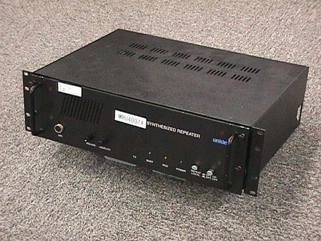
Click to zoom
Application Details
- Equipment Class
- TNB - Licensed Non-Broadcast Station Transmitter
- Date of Grant
- Sep 08, 1998
- Application Purpose
- Original Equipment
- Date of Application
- Jul 16, 1998
- Equipment Note
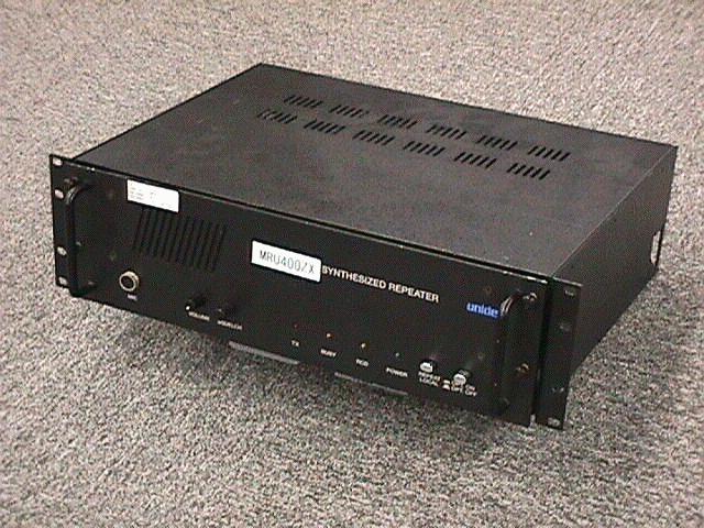
- Land Mobile Transmitter (Driver)
- Frequency Range
- 450.00000000 - 494.00000000
- Company
- Uniden America Corporation
- Country
- United States
Documents & Files
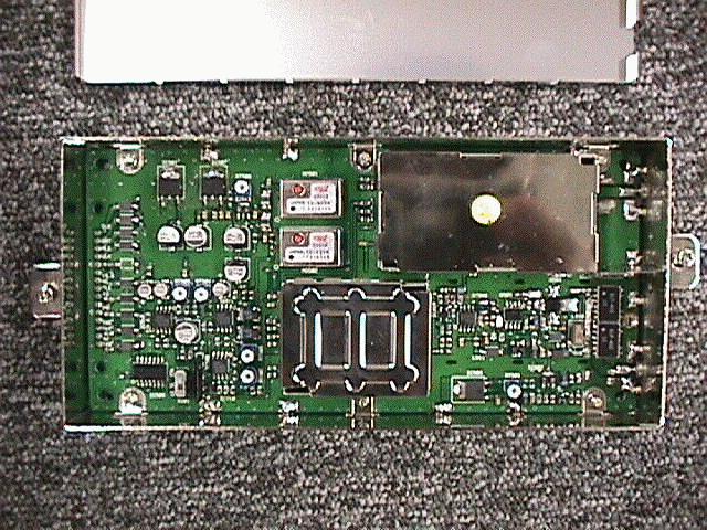
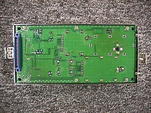
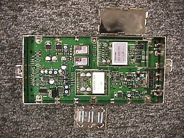
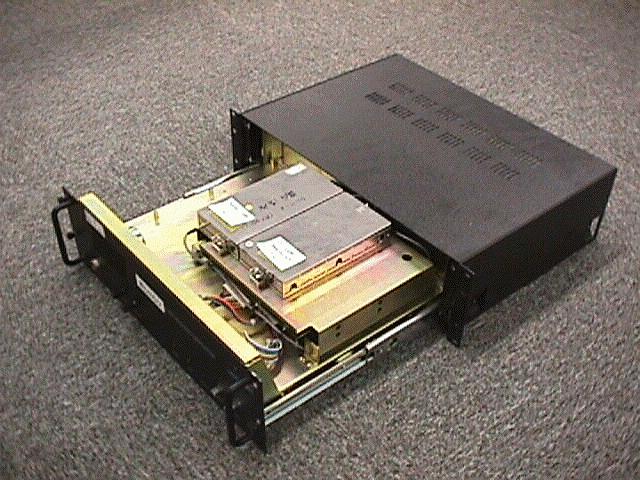
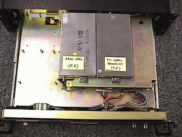
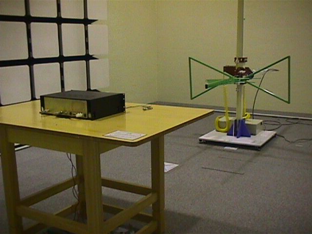
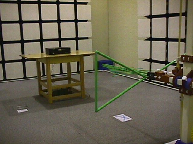
Document Text
Text extracted from the exhibit documents filed with the FCC. Open a document above to read the original.
Users Manual
PRELIMINARY OWNER’S MANUAL CONGRATUALTIONS! You now own the best value in land mobile radio... from Uniden. You’ll find that it gives you consistently outstanding performance in virtually all conditions and situations. Prior to use, your radio must be properly licensed by the Federal Communications Commission (FCC) and properly installed. Your Uniden Dealer will be able to help you with any or all of these requirements and he will be there to assist you with all your future communications needs. BASE STATION OPERATION Base station operation of the MRU400 is as follows: 1. After initial power up, allow a 10 second warm-up period to ensure that the transmitter is within FCC frequency specifications. 2. Rotate the squelch control fully counterclockwise. 3. Turn the squelch control to the right until all background noise disappears. 4. Adjust the volume control for a comfortable listening level. 5. Place the Repeat/Local switch in the “Local” position. 6. The monitor switch is used as follows: a. Switch In : Lets you receive all messages broadcasted on a given channel. b. Switch Out : Lets you hear only those calls meant for you or your group when the microphone is in the hang-up bracket. When a message is received, the CALL light will come on and remain on until you pick up the microphone. This is for the times when you’re away from your station. 7. Before transmitting, monitor your channel to ensure that it is not busy. ( The BUSY light will be on in this situation.) 8. To transmit, depress the Push-To-Talk switch on the side of the microphone and hold it in while you transmit your message. Release the switch when your message is finished. For better voice quality in your transmissions, hold the microphone vertically in front of your face with the top of the microphone approximately level with your lips. 9. When your message is finished and a reply has been made, it is a good practice to always hang-up the microphone. REPEATER OPERATION 1. After initial power up, allow a 10 second warm-up period to ensure that the transmitter is within FCC frequency specifications. 2. Place Repeat/Local Switch in the Repeat position. 3. That’s it! The MRU400 is now a single tone accessed repeater. OPERATING CONTROLS AND THEIR FUNCTIONS The MRU400 Repeater / Base Station is equipped with the following user controls: 1. On/Off Switch – located on the rear panel. When activated the switch applies AC power to the unit. 2. Power indicator light – This LED will glow green during AC power operation and flash green during battery operation. 3. Transmit Light – This LED indicates the presence of a carrier on the RX frequency and enables the user to know that the channel is busy. 4. Busy Light – This LED indicates the presence of a carrier on the RX frequency and enables the user to know that the channel is busy. 5. Mon (Monitor Switch) – By placing this switch in the monitor position the user can monitor position the user can monitor or receive all messages broadcasted on the channel frequency. When the switch is in the “Tone Sq” position, the user will only hear messages intended for his or her group. 6. Call Light – This LED indicator is provided for use when the MRU400 is utilized as a base station. It will come on and remain on when the correct CTCSS tone has been decoded by the receiver, provided the microphone is in the hang up bracket and the “Mon” switch is in the “Tone Sq” position. Reset of the call light can be accomplished by simply removing the microphone from the hang up bracket or monentarily placing the “Mon” switch in the “Mon” position. 7. Repeat/ Local Switch – When this switch is in the “Repeat” position, repeater action is automatic and the repeater can be accessed by another station as well as the local microphone. In the “Local” position, keying of the transmitter can only be accomplished by the use of the microphone. 8. Squelch Control – This control adjust a the Local audio amplifier opening sensitivity and should be adjusted in the following manner. (Note: This control has no effect on repeater operation). a. Rotate the squelch control counterclockwise until background noise is heard. b. Then rotate the control clockwise until the noise just disappears. For best results, leave the control in this position. Turning the control further will result in diminished sensitivity. 9. Volume Control – This control adjusts the local speaker audio output level.
Parts List/Tune Up Info
SEMICONDUCTOR REF No DESCRIPTION TYPE MANUFUCTUER D351 DIODE RLS4148 ROHM D451 DIODE RLS4148 ROHM D502 DIODE RLS4148 ROHM D503 DIODE RLS4148 ROHM IC351 INTEGRATED CIRCUIT MB1501LPF FUJITSU IC352 INTEGRATED CIRCUIT UPC1675G NEC IC353 INTEGRATED CIRCUIT UPB1508GV NEC IC354 INTEGRATED CIRCUIT UPC1678G NEC IC451 INTEGRATED CIRCUIT MB1501LPF FUJITSU IC452 INTEGRATED CIRCUIT UPC1675G NEC IC501 INTEGRATED CIRCUIT BA17805FP ROHM IC502 INTEGRATED CIRCUIT RH5RL50AA RICOH IC503 INTEGRATED CIRCUIT BA05FP ROHM IC506 INTEGRATED CIRCUIT TC4011BF TOSHIBA IC507 INTEGRATED CIRCUIT BA08FP ROHM IC508 INTEGRATED CIRCUIT UPC1678G NEC IC509 INTEGRATED CIRCUIT THB127B TOKO IC510 INTEGRATED CIRCUIT NJM4558M JRC IC511 INTEGRATED CIRCUIT NJM4558M JRC IC512 INTEGRATED CIRCUIT NJM4558M JRC IC513 INTEGRATED CIRCUIT RH5RL40AA RICOH IC514 INTEGRATED CIRCUIT UPC1688G NEC MO351 MODULE:VCO MO-240 HX4088 TOCOS MO451 MODULE:VCO MO-241 HX4088 TOCOS MO501 MODULE:TCXO MO-243 TX1834N TEW MO502 MODULE:TCXO MO-242 TX1834M TEW Q101 TRANSISTOR 2SC3357 NEC Q102 TRANSISTOR 2SC2814 TWN:SANYO Q103 TRANSISTOR 2SC3357 NEC Q104 FET. 2SK323 HITACHI Q107 TRANSISTOR 2SC3356 NEC Q108 TRANSISTOR 2SC3356 NEC Q110 TRANSISTOR DTC114YE ROHM Q452 TRANSISTOR 2SD1048 SANYO Q501 TRANSISTOR 2SB1121 SANYO Q502 TRANSISTOR 2SD1048 SANYO Q503 TRANSISTOR MRF8372R2 MOTOROLA - 1 - SEMICONDUCTOR Q504 TRANSISTOR MRF555 MOTOROLA - 2 - SEMICONDUCTOR FUNCTION SWITCHING SWITCHING BIAS BIAS RX PLL BUFFER PRISCAL BUFFER AMP TX PLL BUFFER REGU 5V REGU 5V REGU 9V GATE REGU 8V TX AMP AUDIO LPF. AUDIO & DATA AMP AUDIO AMP AUDIO AMP REGU 5.6V BUFFER AMP RX VCO TX VCO RX PLL TCXO TX PLL TCXO RF AMP WIDE/NARROW SW LOCAL AMP WIDE/NARROW SW 1st IF AMP 1st IF AMP WIDE/NARROW SW RIPPLE FILTER TX POWER ADJUST TX SW TX DRIVER - 3 - SEMICONDUCTOR TX FINAL - 4 -
Test Report
EQUIPMENT LIST ENG-NO TEST EQUIPMENT TYPE MFR SERIAL NO. 1287 AMPLIFIER AFS30010040020 MITEQ 1383151294 ANTENNA(BILOG) CBL6111 CHASE 10571305 SPECTRUM ANALYZER 8566B HP 2504A014331306 SPECTRUM ANALYZER DISPLAY 85662A HP 2403A090441602 ANTENNA(DIPOLE) 3120-B1 EMCO 751603 ANTENNA(DIPOLE) 3120-B2 EMCO 761604 ANTENNA(DIPOLE) 3120-B3 EMCO 76 524 SPECTRUM ANALYZER TR4173 ADVANTEST 55580013 37 COMMUNICATIONS TEST 8920A HP 3430A0505535 FREQUENCY COUNTER LDC-823A LEADER 877639 629 POWER METER ML4803A ANRITSU M43093 1350 POWER SENSOR MA4601A ANRITSU M35633 615 ATTENUATOR 8498A HP 1801A05152 1617 POWER SUPPLY PAB18-3A KIKUSUI 5040231 509 MULTIMETER E2377A HP 3513J17277656 VOLT/CURRENT METER 2051 HP 67BA2103 1581 CURRENT METER 2051 YEW 67BA37751468 LOW TEMPERATURE CHAMBER MC-71 TABAI ESPEC 660774 631 QUARTS THERMOMETER 2804A HP 1744A00694632 PROBE(QUARTZ THERMOMETER) 18115A HP 2120A¥01580 - 1 - EQUIPMENT LIST CATEGORY CODE 2171 D2121 D2171 D2171 D DDD 2171 42171 42171 4 4444444 2171 42171 42171 4 - 2 -
Contact Information
Applicant
Paul Roby
Technical Specifications
| # | Rule Parts | Frequency Range | Power Output | Emission | Tolerance |
|---|---|---|---|---|---|
| 2 | 90.21 | 450 MHz - 494 MHz | 400.00 mW | 11K0F3E | 0.00015 % |
Other Applications from Uniden America Corporation
AMWUA2405
Apr 15, 2026RADAR DETECTOR
Equipment Class
JBP - Part 15 Class B Computing Device PeripheralAMWUA2406
Apr 15, 2026RADAR DETECTOR
Equipment Class
JBP - Part 15 Class B Computing Device PeripheralAMWUA2402
Jul 23, 2024RADAR DETECTOR
Equipment Class
CRD - Part 15 Radar Detector
AMWUA2404
Feb 17, 2024Wi-Fi Bluetooth Combo Module
Equipment Class
DTS - Digital Transmission System
AMWUA2301
Feb 15, 2023RADAR DETECTOR
Equipment Class
CRD - Part 15 Radar Detector