AMWUN405R1.9 GHz UPCS CORDLESS PHONE-HANDSET
Uniden America Corporation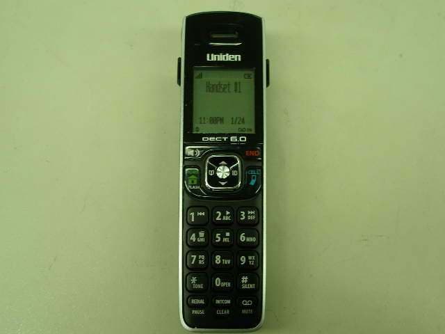
Click to zoom
Application Details
- Equipment Class
- PUE - Part 15 Unlicensed PCS portable Tx held to ear
- Date of Grant
- Apr 18, 2012
- Application Purpose
- Original Equipment
- Date of Application
- Mar 19, 2012
- Equipment Note
- 1.9 GHz UPCS CORDLESS PHONE-HANDSET
- Frequency Range
- 1921.53600000 - 1928.44800000
- Company
- Uniden America Corporation
- Country
- United States
Documents & Files
Document Text
Text extracted from the exhibit documents filed with the FCC. Open a document above to read the original.
Users Manual
D3580 base with answering system and cordless handset Battery cover Accessory handset and charger If you purchased model number: You should have: D3580None D3580-21 of each ...... D3580-1110 of each D3580-1211 of each * If the model number ends in R, your package includes a DRX100 range extender. Refer to the DRX100 User’s Guide for details. You will also find: Not pictured: xRechargeable battery (BT-1031) xAC adapter (PS-0046) xTelephone cord xBelt clip ♦♦If♦any♦items♦are♦missing♦or♦damaged,♦contact♦our♦Customer♦Care♦Line♦immediately.♦ Never♦use♦damaged♦products! ♦♦Need♦help?♦Get♦answers♦24/7♦at♦our♦website: www.uniden.com. If You...Contact Uniden’s...Phone Number have a question or problemCustomer Care Line* 817-858-2929 or 800-297-1023 need a replacement part or an accessory Parts Department*800-554-3988 need special assistance due to a disability Accessibility Help Line 800-874-9314 (voice or TTY) *♦During♦regular♦business♦hours,♦Central♦Standard♦Time;♦see♦our♦website♦for♦detailed♦business♦hours. D3580 Series User's Guide What's in the box? Not pictured: xRechargeable battery (BT-1031) xBelt clip xBattery cover xAC adapter (PS-0035) © 2012 Uniden America Corp. Printed in Vietnam Ft. Worth, Texas U01UN405BZA(0) 2 - English Getting Started ....................................... 3 Installing Your Phone ............................... 3 Getting to Know Your Phone ................. 5 Parts of the Base ......................................... 5 Parts of the Handset ................................. 6 R eading the Display ................................. 7 Using the Handset Menu .................... 8 Entering Text on Your Phone .............. 10 Using Your Phone .................................. 11 Using Your Bluetooth Connection .... 11 Finding a Lost Handset .......................... 12 Changing the Volume ............................ 12 Staying in Range ....................................... 1 2 Using the Caller ID and Redial Lists ... 13 Using Call Waiting .................................... 14 Using the Phonebooks .......................... 14 Using an Optional Headset ................. 16 Silent Mode ............................................... 16 Call Block .................................................... 16 Multihandset Features ........................... 17 Chain Dialing ............................................. 19 Voice Message Notification .................. 19 Using the Answering System .............. 20 Answering System Options (Answering Setup) .............................. 20 Personalizing the Greeting ................. 20 Accessing the Answering System ..... 21 Using the System While You're Away from Home ................... 22 Important Information ......................... 23 Solving Problems .................................... 23 Resetting Handsets ................................ 25 Registering Handsets ............................ 25 Important Safety Instructions! When♦using♦your♦telephone♦equipment,♦basic♦safety♦precautions♦should♦always♦be♦ followed♦to♦reduce♦the♦risk♦of♦fire,♦electric♦shock♦and♦injury♦to♦persons,♦including♦the♦ following:♦ ♦♦This unit is NOT waterproof.♦DO♦NOT♦expose♦it♦to♦rain♦or♦moisture. ♦♦Do♦not♦use♦this♦product♦near♦water,♦for♦example,♦near♦a♦bath♦tub,♦wash♦bowl,♦ kitchen♦sink♦or♦laundry♦tub,♦in♦a♦wet♦basement♦or♦near♦a♦swimming♦pool.♦ ♦♦Avoid♦using♦a♦telephone♦(other♦than♦a♦cordless♦type)♦during♦an♦electrical♦storm.♦ There♦may♦be♦a♦remote♦risk♦of♦electric♦shock♦from♦lightning.♦ ♦♦Do♦not♦use♦the♦telephone♦to♦report♦a♦gas♦leak♦in♦the♦vicinity♦of♦the♦leak.♦ ♦♦Use♦only♦the♦power♦cord♦and♦batteries♦indicated♦in♦this♦manual.♦Do♦not♦dispose♦of♦ batteries♦in♦a♦fire.♦They♦may♦explode.♦Check♦with♦local♦codes♦for♦possible♦special♦ disposal♦instructions.♦ ♦♦Do♦not♦place♦the♦handset♦in♦any♦charging♦cradle♦without♦the♦battery♦installed♦and♦ the♦battery♦cover♦securely♦in♦place. SAVE THESE INSTRUCTIONS! CAUTION! Risk of explosion if battery is replaced by an incorrect type! Dispose of used batteries according to the instructions. Do not open or mutilate the battery. Disconnect the battery before shipping this product. For♦more♦details,♦see♦the♦Important Information♦section. What’s in the manual? English - 3 GETTING STARTED Installing Your Phone Charge the Battery 1.♦Unpack♦all♦handsets,♦ battery♦packs,♦and♦ battery♦covers.♦If♦you♦ need♦to♦remove♦a♦ cover,♦press♦in♦on♦the♦ notch♦and♦slide♦the♦cover♦down♦and♦ off. 2.♦ L ine♦up♦the♦battery♦connector♦with♦ t he♦jack♦inside♦the♦handset;♦the♦ c onnector♦only♦fits♦one♦way.♦ 3.♦Push♦the♦connector♦in♦until♦it♦clicks♦ into♦place;♦tug♦gently♦on♦the♦wires♦ to♦make♦sure♦the♦battery♦is♦securely♦ c onnected. 4. ♦Replace♦the♦battery♦cover♦and♦slide♦it♦ i nto♦place. 5. ♦ U se♦an♦AC♦adapter♦to♦connect♦the♦ power♦jack♦on♦the♦base♦to♦a♦regular♦ i ndoor♦(120V♦AC)♦power♦outlet.♦ Connect♦any♦chargers♦the♦same♦way.♦ 6 .♦ P lace♦a♦handset♦in♦the♦base♦with♦the♦ d isplay♦facing♦forward.♦If♦the♦display♦ d oesn’t♦light♦up,♦reseat♦the♦handset♦or♦ c onnect♦the♦base♦to♦a♦different♦outlet.♦ F or♦2♦or♦more♦handsets,♦place♦each♦ h andset♦in♦a♦charger.♦ #Charge all handsets completely (about 15 hours) before using. Connect the Telephone Cord Use♦the♦telephone♦cord♦to♦connect♦the♦ TEL LINE ♦jack♦on♦the♦base♦to♦a♦standard♦ telephone♦wall♦jack. Test the Connection 1.♦Pick♦up♦the♦handset♦and♦press♦ Home/ Flas H .♦The♦handset♦sounds♦a♦dial♦ tone,♦and♦the♦display♦shows♦Talk.♦ ♦–If♦you♦don't♦hear♦a♦dial♦tone♦or♦the♦ d isplay♦says♦ Check Tel Line, check♦ the♦connection♦between♦the♦base♦ and♦the♦phone♦jack.♦ 2.♦Make♦a♦quick♦test♦call.♦(Press♦ end♦to♦ hang♦up.)♦ ♦–If♦you♦keep♦hearing♦a♦dial♦tone,♦ change♦to♦pulse♦dialing. ♦–If♦there’s♦a♦lot♦of♦noise,♦check♦for♦ interference♦(see♦page♦23).♦ 3.♦Test♦all♦handsets♦the♦same♦way.♦If♦ you♦can't♦get♦a♦dial♦tone,♦move♦the♦ handset♦closer♦to♦the♦base.♦ Changing to Pulse Dialing Your♦phone♦uses♦tone♦dialing♦by♦default.♦ If♦your♦phone♦company♦uses♦pulse♦ dialing,♦you♦need♦to♦change♦your♦phone’s♦…
Text truncated - open the document above for the full version.
Cover Letter(s)
Uniden America Corporation 4700 Amon Carter Blvd. Fort Worth, TX 76155 817-858-3300 Fax: 817-858-3328 February 3, 2012 TIMCO Engineering, Inc. 849 NW State Road 45 P.O. Box 370 Newberry, Florida 32669 Re.: Letter of Explanation for Uniden Model D3580 1.9 GHz UPCS Cordless Phone – Handset Unit SAR exemption FCC ID: AMWUN405R Product Type: 1.9 GHz UPCS Cordless Phone – Handset Unit To Whom It May Concern: UPCS DECT 6.0 Cordless Handset SAR exemption for FCC TCB Certification under Part 15D: These handsets operate at a very low source-based time-averaged duty cycle with a typical source-based time- averaged output power of < 6 mW. For FCC TCB Certification of these handsets, SAR testing has been excluded since the maximum source-based time-averaged output power is < 60/f mW per it operates with a maximum of 1 TDMA slot out of the 24 total slots. This document serves as the RF exposure exhibit in the FCC Form 731 application in lieu of a SAR report and has been reviewed and accepted by the FCC prior to submittal to the TCB. Operational Description: Above mentioned model is a DECT 6.0 Cordless Handset. It operates at frequency range of 1920 to 1930 MHz with 5 channels. RF Exposure Conditions: The Handset is intended for use in the portable exposure condition and the General Population / Uncontrolled RF exposure environment. Transmission Mode: This DECT 6.0 Cordless Handset utilizes a DECT wireless communication technology with a maximum of 1 TDMA slot out of the 24 total slots. Uniden America Corporation 4700 Amon Carter Blvd. Fort Worth, TX 76155 817-858-3300 Fax: 817-858-3328 Duty Cycle: DECT 6.0 Cordless Handset operates with a maximum of 1 TDMA slot out of the 24 total slots. The length of time for each single slot is 416.7μ Seconds and the 24 total slots is 10m Seconds as a transmission period. RF Output Power: Tx frequency range: 1920 – 1930 MHz Antenna-to-tissue phantom separation: 2mm Maximum Output Power: 19.1 dBm (81mW) Maximum Duty Factor: 4.16% 60/f(GHz) mW = 31.17mW Source-based time-averaged conducted output power is 3.470mW = < 60/f Please contact the undersigned if you have any questions or need any further information regarding this matter. Regards, Jon Suehiro Manager, Engineering and Regulatory Affairs
Cover Letter(s)
Uniden America Corporation 4700 Amon Carter Blvd. Fort Worth, TX 76155 817-858-3300 Fax: 817-858-3328 REQUEST FOR CONFIDENTIALITY February 3, 2012 To: Federal Communications Commission Equipment Authorization Branch Laboratory Division Office of Engineering and Technology 7435 Oakland Mills Road Columbia, Maryland 21046 Subject: Data for FCC Certification Applicant: Uniden America Corporation 4700 Amon Carter Blvd., Fort Worth, Texas 76155 Jon Suehiro, Manager – Engineering and Regulatory Affairs TYPE OF EQUIPMENT: UPCS 1.9 GHz Cordless Telephone Handset Unit FCC IDENTIFIER: AMWUN405R Dear Sir or Madam: Some of the material included in this application contains trade secrets and proprietary information not customarily released to the public. Because public disclosure of the material might be harmful to the applicant and provide unjustified benefits to its competitors, it is requested that the following be withheld from public disclosure: Circuit Description (AMWUN405R_Circuit Description.pdf) Schematic Diagrams (AMWUN405R_Schematic Diagram.pdf) Block Diagrams (AMWUN405R_Block Diagram.pdf) Trade secrets and proprietary information can be held confidential. Therefore, we wish to invoke the act under the provisions of 47CFR, Sections 0.457(d) and 0.459. Please contact the undersigned if you have any questions or need any further information. Regards, Jon Suehiro Manager, Engineering and Regulatory Affairs
Cover Letter(s)
Dear Timco Engineering, I hope this reply will solve the FCC pending and we can obtain the FCC Grant very soon. Our Letter of Explanation is already explaining the maximum slot usage regardless the featured mode such range extender (data rate and time slot reduction), intercom call, call conferencing, call forwarding, 2nd incoming call, call waiting, etc as FCC is concerning about. I also checked the actual files uploaded to your site as this FCC ID: AMWUN405R application, and I should have been added the file “D3580 Part 15D Declarations.doc” to this application. Please let me know if I need to upload this file to your site separately under JOB #: 290NC12. Please see this Declarations defines AMWUN405R’s “Max number of slots in use simultaneously” to “1”. the various duty cycles will not be happening in FCC ID: AMWUN405R communication. Transmission Mode: This DECT 6.0 Cordless Handset utilizes a DECT wireless communication technology with a maximum of 1 TDMA slot out of the 24 total slots.
Cover Letter(s)
FCC Part 15D – Compliance Information d3580 part 15d declarations_rev.doc 8-Dec-2006 page 1 (4) rev.1.4 EUT AND PRODUCT INFORMATION Type of Equipment UPCS (DECT 6.0) Applicant Name Uniden America Corporation Address 4700 Amon Carter Blvd, Fort Worth, Texas 76155 U.S.A. Contact Jon Suehiro FP PP Repeater EUT Type/System FCC ID AMWUN405 AMWUN405R Model name D3580 D3580 HW Version 1.0 1.0 SW Version 0.08 0.08 Max antenna Gain -2dBi -3dBi Can the EUT be Initiating Device YES YES YES Does the EUT transmit signaling channels YES YES YES Max number of slots in use simultaneously 4 1 Test standard: FCC part 15D Other: RSS-213, Issue 2 Frequency Band 1921.536 – 1928.448 MHz # of RF Channels 5 Frame Period 10 ms Max. Burst length 10 ms Min. Burst Length 10 ms # of Logical Channels 60 (12 duplex channels per RF carrier) Operating Mode Simplex Duplex FCC Part 15D – Compliance Information d3580 part 15d declarations_rev.doc 8-Dec-2006 page 2 (4) rev.1.4 ANTENNAS Base (FP) Antenna Type Internal External 1 Dipole 2 Dipole 3 4 Does RX and TX use the same antenna(s)? Yes No Handset (PP) Antenna Type Internal External 1 monopole 2 Does RX and TX use the same antenna(s)? Yes No ANTENNA DIVERSITY Antenna Diversity Supported TX RX Base (FP) 1 2 3 4 Handset (PP) 1 2 VOLTAGE AND TEMPERATURE RANGES VOLTAGES FP PP Repeater Nominal Voltage 120 V AC 2.4 V DC Cut-Off Voltage (if applicable) N/A 2.15V POWER SOURCE Type Manufacturer Base or Repeater AC Adaptor Ten Pao International Ltd. Handset (PP) (charger) Ni-MH Battery Yiyang Corun Battery Co., Ltd. Data Connections PSTN Others (please specify) .... FCC Part 15D – Compliance Information d3580 part 15d declarations_rev.doc 8-Dec-2006 page 3 (4) rev.1.4 ANCILLARY EQUIPMENT Description Type Manufacturer HOST DEVICE Description Type Manufacturer ADDITIONAL INFORMATION FCC Part 15D – Compliance Information d3580 part 15d declarations_rev.doc 8-Dec-2006 page 4 (4) rev.1.4 MANUFACTURERS DECLARATIONS FCC part 15.323 (c)(5) No device or group of co-operating devices located within 1m of each other shall during any frame period occupy more than 6 MHz of aggregate bandwidth, or alternatively, more than one third of the time and spectrum windows defined by the system. Applicant Agrees Yes No FCC part 15.323 (c)(10) The applicant hereby declares that the system in this application does use the criteria of (c)(10) of this section. Applicant Agrees Yes No FCC part 15.323 (c)(11) The applicant hereby declares that system in this application does not use the criteria of (c)(11) of this section. Applicant Agrees Yes No FCC part 15.323 (c)(12) The provisions of (c)(10) or (c)(11) of this section shall not be used to extend the range of spectrum occupied over space or time for the purpose of denying fair access to spectrum to other devices. Applicant Agrees Yes No FCC part 15.307 (b) The Applicant is a participating member of UTAM, Inc. and will provide an affidavit from UTAM, Inc. certifying this. Confirmed By Applicant Yes No ADDITIONAL REMARKS: > DECLARED BY: > Date: January 30, 2012 > Name (print): Jon Suehiro Signature
External Photos
FCC ID: AMWUN405R 1 External Photos Front View Rear View
ID Label/Location Info
FCC ID: AMWUN405R 1 Equipment Identification Label Equipment Labels: The following markings are permanently affixed to the Base Unit: 1) 16 mm(W) x 22 mm(H) 2) 9 mm(W) x 21.5 mm(H) by Engraving by Label
ID Label/Location Info
FCC ID: AMWUN405R 1 Equipment Identification Label Equipment Labels: The following markings are permanently affixed to the Base Unit: 1) 16 mm(W) x 22 mm(H) 2) 9 mm(W) x 21.5 mm(H) by Engraving by Label
Internal Photos
FCC ID: AMWUN405R 1 Internal Photos Rear Cover opened FCC ID: AMWUN405R 2 Main PCB Top View FCC ID: AMWUN405R 3 Main PCB Bottom View
RF Exposure Info
Uniden America Corporation 4700 Amon Carter Blvd. Fort Worth, TX 76155 817-858-3300 Fax: 817-858-3328 February 3, 2012 TIMCO Engineering, Inc. 849 NW State Road 45 P.O. Box 370 Newberry, Florida 32669 Re.: Letter of Explanation for Uniden Model D3580 1.9 GHz UPCS Cordless Phone – Handset Unit SAR exemption FCC ID: AMWUN405R Product Type: 1.9 GHz UPCS Cordless Phone – Handset Unit To Whom It May Concern: UPCS DECT 6.0 Cordless Handset SAR exemption for FCC TCB Certification under Part 15D: These handsets operate at a very low source-based time-averaged duty cycle with a typical source-based time- averaged output power of < 6 mW. For FCC TCB Certification of these handsets, SAR testing has been excluded since the maximum source-based time-averaged output power is < 60/f mW per it operates with a maximum of 1 TDMA slot out of the 24 total slots. This document serves as the RF exposure exhibit in the FCC Form 731 application in lieu of a SAR report and has been reviewed and accepted by the FCC prior to submittal to the TCB. Operational Description: Above mentioned model is a DECT 6.0 Cordless Handset. It operates at frequency range of 1920 to 1930 MHz with 5 channels. RF Exposure Conditions: The Handset is intended for use in the portable exposure condition and the General Population / Uncontrolled RF exposure environment. Transmission Mode: This DECT 6.0 Cordless Handset utilizes a DECT wireless communication technology with a maximum of 1 TDMA slot out of the 24 total slots. Uniden America Corporation 4700 Amon Carter Blvd. Fort Worth, TX 76155 817-858-3300 Fax: 817-858-3328 Duty Cycle: DECT 6.0 Cordless Handset operates with a maximum of 1 TDMA slot out of the 24 total slots. The length of time for each single slot is 416.7μ Seconds and the 24 total slots is 10m Seconds as a transmission period. RF Output Power: Tx frequency range: 1920 – 1930 MHz Antenna-to-tissue phantom separation: 2mm Maximum Output Power: 19.1 dBm (81mW) Maximum Duty Factor: 4.16% 60/f(GHz) mW = 31.17mW Source-based time-averaged conducted output power is 3.470mW = < 60/f Please contact the undersigned if you have any questions or need any further information regarding this matter. Regards, Jon Suehiro Manager, Engineering and Regulatory Affairs
Test Report
FCC Part 15D – Compliance Information d3580 part 15d declarations-new.doc 8-Dec-2006 page 1 (4) rev.1.4 EUT AND PRODUCT INFORMATION Type of Equipment UPCS (DECT 6.0) Applicant Name Uniden America Corporation Address 4700 Amon Carter Blvd, Fort Worth, Texas 76155 U.S.A. Contact Jon Suehiro FP PP Repeater EUT Type/System FCC ID AMWUN405 and AMWUN405BT AMWUN405R Model name D3580 D3580 HW Version 1.0 1.0 SW Version 0.08 0.08 Max antenna Gain -2dBi -3dBi Can the EUT be Initiating Device YES YES YES Does the EUT transmit signaling channels YES YES YES Max number of slots in use simultaneously 4 1 Test standard: FCC part 15D Other: RSS-213, Issue 2 Frequency Band 1921.536 – 1928.448 MHz # of RF Channels 5 Frame Period 10 ms Max. Burst length 10 ms Min. Burst Length 10 ms # of Logical Channels 60 (12 duplex channels per RF carrier) Operating Mode Simplex Duplex FCC Part 15D – Compliance Information d3580 part 15d declarations-new.doc 8-Dec-2006 page 2 (4) rev.1.4 ANTENNAS Base (FP) Antenna Type Internal External 1 Dipole 2 Dipole 3 4 Does RX and TX use the same antenna(s)? Yes No Handset (PP) Antenna Type Internal External 1 monopole 2 Does RX and TX use the same antenna(s)? Yes No ANTENNA DIVERSITY Antenna Diversity Supported TX RX Base (FP) 1 2 3 4 Handset (PP) 1 2 VOLTAGE AND TEMPERATURE RANGES VOLTAGES FP PP Repeater Nominal Voltage 120 V AC 2.4 V DC Cut-Off Voltage (if applicable) N/A 2.15V POWER SOURCE Type Manufacturer Base or Repeater AC Adaptor Ten Pao International Ltd. Handset (PP) (charger) Ni-MH Battery Yiyang Corun Battery Co., Ltd. Data Connections PSTN Others (please specify) .... FCC Part 15D – Compliance Information d3580 part 15d declarations-new.doc 8-Dec-2006 page 3 (4) rev.1.4 ANCILLARY EQUIPMENT Description Type Manufacturer HOST DEVICE Description Type Manufacturer ADDITIONAL INFORMATION FCC Part 15D – Compliance Information d3580 part 15d declarations-new.doc 8-Dec-2006 page 4 (4) rev.1.4 MANUFACTURERS DECLARATIONS FCC part 15.323 (c)(5) No device or group of co-operating devices located within 1m of each other shall during any frame period occupy more than 6 MHz of aggregate bandwidth, or alternatively, more than one third of the time and spectrum windows defined by the system. Applicant Agrees Yes No FCC part 15.323 (c)(10) The applicant hereby declares that the system in this application does use the criteria of (c)(10) of this section. Applicant Agrees Yes No FCC part 15.323 (c)(11) The applicant hereby declares that system in this application does not use the criteria of (c)(11) of this section. Applicant Agrees Yes No FCC part 15.323 (c)(12) The provisions of (c)(10) or (c)(11) of this section shall not be used to extend the range of spectrum occupied over space or time for the purpose of denying fair access to spectrum to other devices. Applicant Agrees Yes No FCC part 15.307 (b) The Applicant is a participating member of UTAM, Inc. and will provide an affidavit from UTAM, Inc. certifying this. Confirmed By Applicant Yes No ADDITIONAL REMARKS: > DECLARED BY: > Date: January 30, 2012 > Name (print): Jon Suehiro Signature
Test Report
Nemko AS, Gaustadalléen 30, P.O.Box 73 Blindern, NO-0314 Oslo Norway T +47 22 96 03 30 F +47 22 96 05 50 Enterprise number NO974404532 Visiting address: Nemko Kjeller, Instituttveien 6, P.O.Box 96, NO-2027 Kjeller Norway T +47 64 84 57 00 F +47 64 84 57 05 Test report no. : 193682-3 Item tested : D3580 Type of equipment : UPCS Handset FCC ID : AMWUN405R Client : Uniden America Corporation FCC Part 15, subpart D Isochronous UPCS Device 1920 - 1930 MHz Industry Canada RSS-213, Issue 2 2 GHz Licence-exempt Personal Communications Service Devices (LE-PCS) 2 February 2012 Authorized by : .............................................. G. Suhantakumar Technical Verificator TEST REPORT FCC part 15D Report no.: 193682-3 FCC ID: AMWUN405R Nemko AS, N-2007 Kjeller Page 2 (52) CONTENTS 1 GENERAL INFORMATION ............................................................................................................... 3 1.1 Testhouse Info ................................................................................................................................... 3 1.2 Client Information .............................................................................................................................. 3 1.3 Manufacturer (if other than client) ...................................................................................................... 3 2 TEST INFORMATION ....................................................................................................................... 4 2.1 Tested Item........................................................................................................................................ 4 2.2 Description of Tested Device ............................................................................................................. 4 2.3 Exposure Evaluation .......................................................................................................................... 5 2.4 Test Environment .............................................................................................................................. 5 2.5 Test Period ........................................................................................................................................ 5 2.6 Test Engineer(s) ................................................................................................................................ 5 2.7 Test Equipment ................................................................................................................................. 5 2.8 Other Comments ............................................................................................................................... 5 3 TEST REPORT SUMMARY .............................................................................................................. 6 3.1 General .............................................................................................................................................. 6 3.2 Test Summary ................................................................................................................................... 7 4 TEST RESULTS ................................................................................................................................ 8 4.1 Power Line Conducted Emissions ..................................................................................................... 8 4.2 Coordination with fixed microwave .................................................................................................. 10 4.3 Digital Modulation Techniques ........................................................................................................ 10 4.4 Labeling Requirements ................................................................................................................... 10 4.5 Antenna Requirement...................................................................................................................... 11 4.6 Channel Frequencies ...................................................................................................................... 11 4.7 Automatic Discontinuation of Transmission .................................................................................... 12 4.8 Peak Power Output ......................................................................................................................... 13 4.9 Emission Bandwidth B ..................................................................................................................... 18 4.10 Power Spectral Density ................................................................................................................... 21 4.11 In-Band Unwanted Emissions, Conducted ...................................................................................... 24 4.12 Out-of-band Emissions, Conducted................................................................................................. 26 4.13 Carrier Frequency Stability .............................................................................................................. 33 4.14 Frame Repetition Stability ............................................................................................................... 34 4.15 Frame Period and Jitter ................................................................................................................... 34 4.16 Monitoring Threshold, Least Interfered Channel ............................................................................. 36 4.17 Threshold Monitoring Bandwidth ..................................................................................................... 38 4.18 Reaction Time and Monitoring Interval ............................................................................................ 39 4.19 Time and Spectrum Window Access Procedure ............................................................................. 41 4.20 Ackn…
Text truncated - open the document above for the full version.
Test Setup Photos
FCC ID: AMWUN405R Project no.: 193682 Page 1 of 1 PHOTOS OF TEST SET-UP – D3580 Handset Antenna Gain Test Power line Conducted Emissions Test Set-up
Contact Information
Applicant
Paul Roby
Test Firm
Nemko ASFrode Sveinsen
Technical Specifications
| # | Rule Parts | Frequency Range | Power Output |
|---|---|---|---|
| 1 | 15D | 1.92 GHz - 1.93 GHz | 81.00 mW |
Other Applications from Uniden America Corporation
AMWUA2405
Apr 15, 2026RADAR DETECTOR
Equipment Class
JBP - Part 15 Class B Computing Device PeripheralAMWUA2406
Apr 15, 2026RADAR DETECTOR
Equipment Class
JBP - Part 15 Class B Computing Device PeripheralAMWUA2402
Jul 23, 2024RADAR DETECTOR
Equipment Class
CRD - Part 15 Radar Detector
AMWUA2404
Feb 17, 2024Wi-Fi Bluetooth Combo Module
Equipment Class
DTS - Digital Transmission System
AMWUA2301
Feb 15, 2023RADAR DETECTOR
Equipment Class
CRD - Part 15 Radar Detector