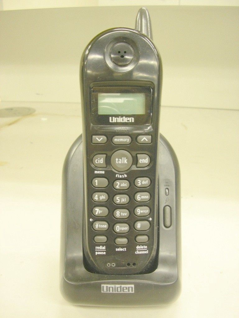
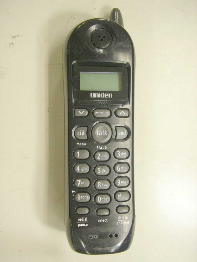
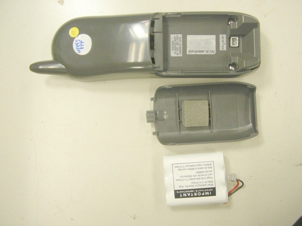
AMWUP095RCORDLESS TELEPHONE- REMOTE UNIT
Uniden America Corporation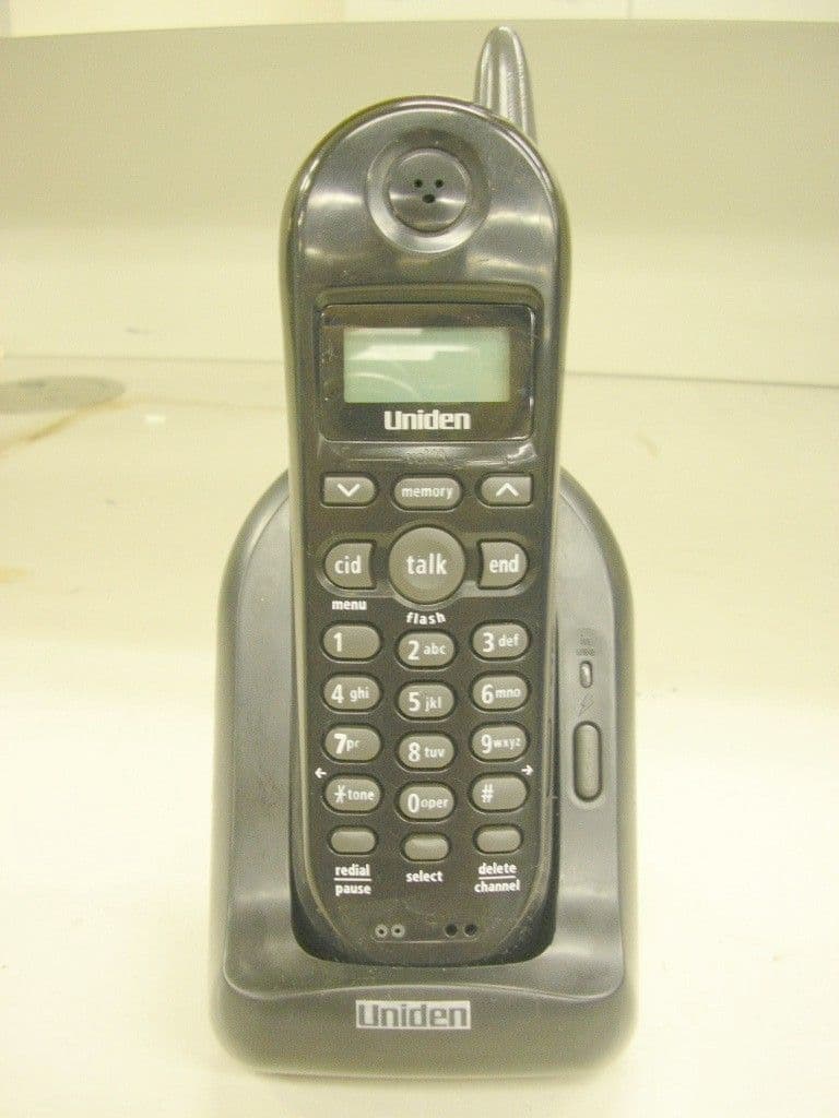
Click to zoom
Application Details
- Equipment Class
- DXX - Part 15 Low Power Communication Device Transmitter
- Date of Grant
- Oct 16, 2006
- Application Purpose
- Original Equipment
- Date of Application
- Oct 15, 2006
- Equipment Note
- CORDLESS TELEPHONE- REMOTE UNIT
- Frequency Range
- 924.51692500 - 926.70442500
- Company
- Uniden America Corporation
- Country
- United States
Documents & Files
Document Text
Text extracted from the exhibit documents filed with the FCC. Open a document above to read the original.
Users Manual
UP095BH.indd AUP095BH.indd A 9/26/2006 5:51:19 PM9/26/2006 5:51:19 PM 1 Setup GuideEXI4560/EXI4561 Step 1 Check the Package Contents Make sure your cordless phone’s packaging includes the following items. Base Handset AC adapter Rechargeable battery Telephone cord Also included: • Owner’s manual Step 2 Install the Handset Battery Pack Note Use ONLY the Uniden rechargeable battery pack supplied with your new phone! Remove the cover.Connect the battery pack with the correct polarity.Replace the cover. Step 3 Set up the Base Plug the AC adapter cord to the DC IN 9V jack (yellow). Route the cord. Plug the AC adapter to a 120V AC power outlet. Note Use ONLY the Uniden AC adapter supplied with your new phone! Step 4 Charge the Handset Place the handset in the base.Make sure that charge LED illuminates. Charge for 15-20 hours before using your phone. Step 5 Connect to the Phone Line Plug the other end into the telephone wall jack. Route the cord. Plug one end of the telephone cord into the base TEL LINE jack. Step 6 Make & Receive Calls To Make a Call Press talk/ fl ash . Listen for dial tone. Dial the desired number. To Receive a CallPick up the handset and press talk/ fl ash . To Hang Up a CallPress end or return the handset to the base. Additional Features For more information on these and other features, please refer to your Owner’s Manual. For your convenience, listed below are important features that will help you set up your new cordless phone. Handset/Base Set up:- Adjust the Earpiece Volume o P.25 - Set the Ringer Volume o P.25 - Set Tone/Pulse Dialing o P.17 Caller ID:Set Caller ID on Call Waiting (CIDCW) o P.15 Note: You must subscribe to Caller ID services through your local telephone provider to use Caller ID and CIDCW. Refer to your Owner’s Manual for detailed operations.For answers to questions and to order genuine Uniden parts and accessories 24 hours a day visit our website at www.uniden.com. If you have any problems, you can also call our Customer Hotline at 1-800-297-1023, Mon-Fri 7 a.m. to 7 p.m., Sat/Sun 9 a.m. to 5 p.m. CST. (Phone support is closed on holidays.) UP095BH.indd 1UP095BH.indd 1 9/26/2006 5:51:20 PM9/26/2006 5:51:20 PM 2 Guía de programaciónEXI4560/EXI4561 1° Paso Inspección del contenido del embalaje Asegúrese de que haya recibido los siguientes artículos en el paquete Base Receptor Adaptador CA Pila recargable Cable telefónico Además va incluido: • Manual del usuario 2° Instalación del paquete de pilas del receptor Nota ¡Use SOLAMENTE el paquete de pilas recargable de Uniden suministrado con su nuevo teléfono! Quite la tapa. negronegronegro negronegro rojo rojo Conecte el paquete de pilas con la polaridad correcta.Reponga la tapa 3° Paso Preparación de la base Conecte el adaptador CA en el enchufe (amarillo) DC IN 9V . Pase el cable A la toma CA Al enchufe DC IN 9V Adaptador CA (suministrado) Conecte el adaptador CA en una toma de 120V CA. Nota ¡Use SOLAMENTE el adaptador CA de Uniden suministrado con su teléfono! 4° Paso Carga del receptor Coloque el receptor en la base.Asegúrese de que el LED de carga se ilumine. Cargue el receptor de 15 a 20 horas antes de usar el teléfono. 5° Paso Conexión de la línea telefónica Conecte el otro extremo en el enchufe telefónico de la pared. Al enchufe telefónico Pase el cable Cable de la línea telefónica (suministrado) Al enchufe TEL LINE Conecte un extremo de la línea telefónica en el enchufe TEL LINE en la base. 6° Paso Realización y recepción de llamadas Para hacer una llamada Oprima talk/ fl ash . Espere por el tono de marcación.Marque el número deseado. Para recibir una llamadaLevante el receptor y oprima talk/ fl ash . Para colgar una llamadaOprima end o devuelva el receptor a la base. Características adicionales Para más información sobre estas y otras características, le rogamos que consulte su Manual del usuario. Para su conveniencia, hemos listado abajo unas características importantes, las cuales le ayudarán a programar su nuevo teléfono inalámbrico de Uniden. Programación del receptor/base:- Ajuste del volumen del auricular y del altavoz o P.25 - Programación del volumen del timbre o P.25 - Programación de la marcación por tono/pulso o P.17 Identi fi cación de llamadas (Caller ID): Programe la Identi fi cación de llamadas en Llamadas en espera (CIDCW) o P.15 Nota: Usted debe estar suscrito al servicio de Identi fi cación de llamadas con su proveedor de telefonía local para poder usar las características de Caller ID y de CIDCW Consulte su manual del usuario para operaciones más detalladas.Para hacer preguntas u ordenar partes genuinas y accesorios de Uniden, llame a nuestra línea para atención al cliente en el 1-800-297-1023.Horario:Lunes - viernes: 7 de la mañana- 7 de la tarde. Sábado/domingo: 9 de la mañana - 5 de la tarde. No habrá ayuda telefónica los días festivos. O, visite nuestra página Web: http://www.uniden.com UP095BH.indd 2UP095BH.indd 2 9/26/2006 5:51:21 PM9/26/2006 5:51:21 PM 3 Setup Guide ...................................................................1Welcome/ Accessibility .................................................4Terminology/ Manual Conventions ..............................5Product Overview ..........................................................6Controls and Functions ................................................7Installing the Phone ......................................................9 Choosing the Best Location ................................................ 9Installing the Rechargeable Battery Pack into the Handset....................................................................... 10 Installing the Base Unit ..................................................... 11Mounting the Base Unit on a Wall ..................................... 13 Basic Setup ..................................................................15 Activating AutoTalk ............................................................ 15Activating Caller ID on Call Waiting ...............................…
Text truncated - open the document above for the full version.
Cover Letter(s)
REQUEST FOR CONFIDENTIALITY October 12, 2006 To: Federal Communications Commission Equipment Authorization Branch Laboratory Division Office of Engineering and Technology 7435 Oakland Mills Road Columbia, Maryland 21046 Subject: Data for FCC Certification Applicant: Uniden America Corporation 181 N. Country Club Road, P.O. Box 580 Lake City, South Carolina 29560 James R. Haynes, Vice President, Engineering and Regulatory Affairs TYPE OF EQUIPMENT: 900 MHz Cordless Telephone Remote Unit - Part 15.249 FCC IDENTIFIER: AMWUP095R Dear Sir or Madam: Some of the material included in this application contains trade secrets and proprietary information not customarily released to the public. Because public disclosure of the material might be harmful to the applicant and provide unjustified benefits to its competitors, it is requested that the following be withheld from public disclosure: Circuit Descriptions and Test Mode Information Schematic Diagrams Block Diagrams Trade secrets and proprietary information can be held confidential. Therefore, we wish to invoke the act under the provisions of 47CFR, Sections 0.457(d) and 0.459. Please contact the undersigned if you have any questions or need any further information. Regards, James R. Haynes Vice President, Engineering and Regulatory Affairs
ID Label/Location Info
Equipment Identification Label Equipment Label: The following label is permanently affixed to the Handset. HANDSET: 30 mm (W) X 20 mm (H) FCC STATEMENT: To be described in user manual
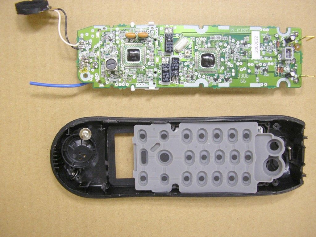
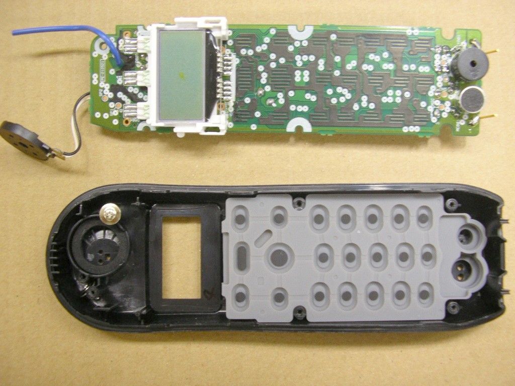
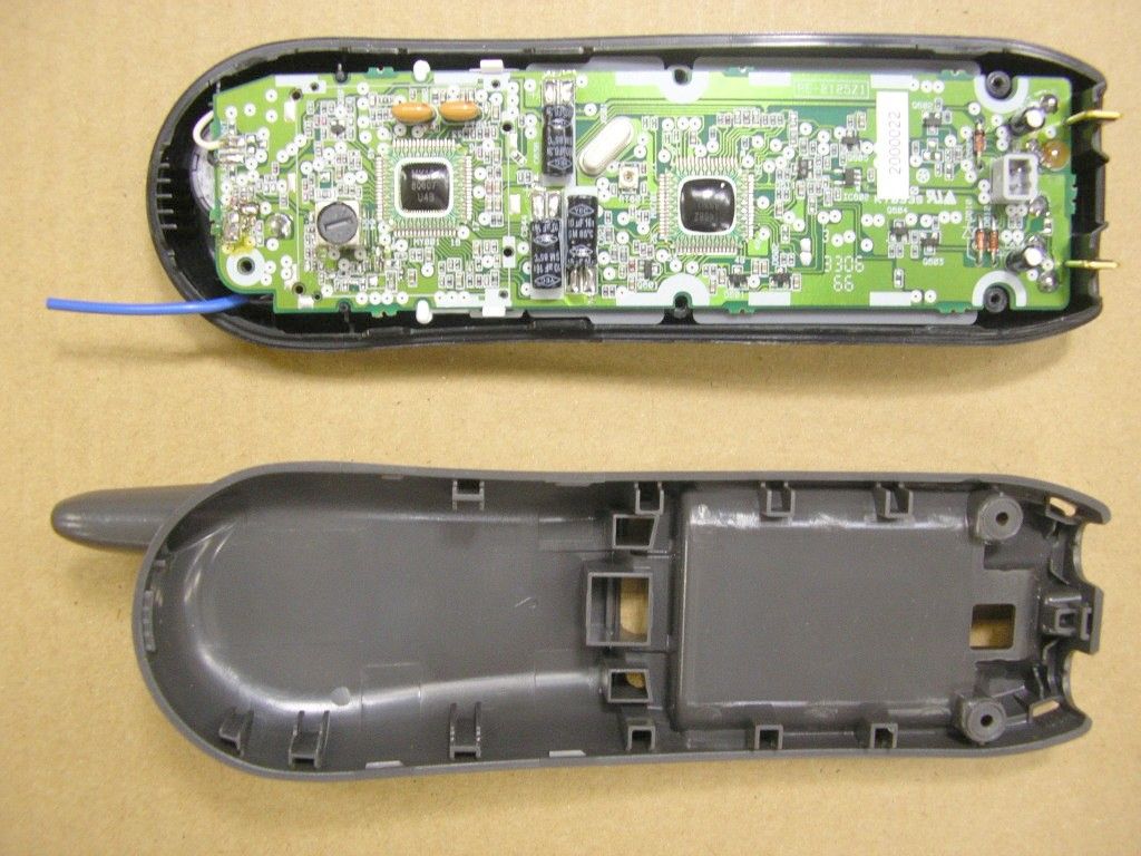
Internal Photos
GENERAL INFORMATION General Information in accordance with the Federal Communications Commission Rules and Regulations, Volume II, Part 2. (1) Applicant: Uniden America Corporation 181 N. Country Club Road, P.O. Box 580 Lake City, South Carolina 29560 Mr. James R. Haynes, Vice President, Eng & Reg Affairs (2) FCC Identifier: FCC ID: AMWUP095R MODEL: EXI4561 (FOR HANDSET) (3) Instruction Manual: Refer to User Manual (4) Circuit Description: Refer to Operational Description (5) Circuit & Block Diagrams: Refer to Block Diagram / Schematics (6) Measurement Data: Refer to Test Report The following conditions and procedures were followed during testing of the equipment. Room Temperature: 23 - 27 Degrees Celsius Room Humidity: 40 - 60 % Power Supply: Ni-cad Battery for Handset (7) Photographs : Refer to External Photos (8) Peripheral or Accessory Device: Not used (9) Transition provisions in section 15.37 Rules: This equipment complies with the new Part 15 of FCC Rules and is not affected by Section 15.37. (10) Decoding the Emergency Broadcast System Attention Signal: Not Applicable (11) Direct Sequence Spread Spectrum Transmitter: Not Applicable (12) Digital Security Code Information: UP095R-15. doc 2
Test Report
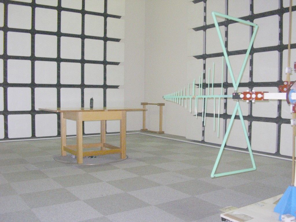
Test Report TEST PROCEDURES AND TEST SITE DESCRIPTION MEASUREMENT ITEMS Section No. 5-1 Field Strength of Radiated Emissions 15.249(a)(b) 15.205 / 15.209 5-2 Power Line Conducted Emissions 15.207 SUPPLEMENT DATA - BAND EDGE EMISSIONS FCC ID: AMWUP095R MODEL: EXI4561 (for HANDSET) EQUIPMENT: 900MHz ISM BAND ANALOG TRANSMITTER DATE: October 2, 2006 Tested by: Mr. S. Takamiya, Uniden Corporation 5-1 Field Strength of Radiated Emissions 15.249(a)(b) 15.205 / 15.209 The measurements were performed in accordance with the ANSI C63.4-2003. Field Strength measurements of radiated spurious emissions were made at the open test site of a 3 meter range maintained by Uniden Corporation in Japan. Complete description and measurement data of this test site have been placed on file with the Commission. The radio frequency spectrum was scanned in the range of 30 MHz to the 10 th harmonic in accordance with the section 15.33(a) of the FCC Rules. The frequency below 1 GHz, the measurement was carried out by using CISPR quasi-peak detector, AGILENT E7400A the Spectrum Analyzer in accordance with the sections 15.33(a) and 15.35(a). The frequency above 1 GHz, using the AGILENT E7400A Spectrum Analyzer in accordance with the section 15.35(b) carried out the measurement. A bilog antenna CBL6112A was used to cover the range from 30 MHz to 1000 MHz. Narrowband tuned dipole antennas were used over the entire 30 to 1000 MHz range for precision measurements of field strength. Above 1000 MHz, a horn antenna EMCO 3115 was used. For each spurious or harmonic frequency, the antenna was raised and lowered to obtain a maximum reading on the Spectrum Analyzer with antenna horizontally polarized. Then the turntable, on which the equipment under test was placed, was rotated a minimum of 360 degrees to further increase the reading on the Spectrum Analyzer. For testing small and/or handheld product, the measurement was performed in 3 orthogonal planes(X, Y, Z). This procedure was repeated with the antenna vertically polarized. The equipment under test was placed in its normal operating position on a turntable approximately 1 meter in height. In order to convert the measured emission levels into field strength in dBuV/m, the actual field strength (Ef) is determined by algebraically adding the measured emission level (Em) and the antenna correction factor (ACF) including the cable loss at the appropriate frequency. Ef [dBuV/m] = Em [dBuV/m] + ACF [dB] FCC Limits: a) Fundamental emission: 94 dBuV/m (50,000 uV/m) b) Spurious emissions: 30 - 88 MHz 40 dBuV/m (100 uV/m) 88 - 216 MHz 43.5 dBuV/m (150 uV/m) 216 - 960 MHz 46 dBuV/m (200 uV/m) Above 960 MHz 54 dBuV/m (500 uV/m) Test Results: Refer to the attached test reports. All emissions not reported were more than 20 dB below the limits. NOTE: For measurement of the handset, all of the testing were made with the internal battery that is fully charged. For measurement of base unit, all of the testing weremade with the AC Adapter which connected to a standardvoltage source. 5-2 Power Line Conducted Emissions 15.207 Test Procedure: The measurements were performed in accordance with the ANSI C63.4- 2003 . During the measurements, a standard voltage source is fed into the unit under test through a power line impedance stabilization network. FCC Limit: The radio frequency voltage that is conducted back into the AC power line on any frequencies within the band from 150kHz to 30MHz shall not exceed the following limitation. REQUIREMENTS: FREQUENCY(MHz) LEVEL (dBuV) 0.150-0.50 66 to 56 QP 56 to 46 Ave 0.50-5.0 56 QP 46 Ave 5.0-30.0 60 QP 50 Ave Test Results: Refer to the attached test reports. All emissionsnot reported were more than 20 dB below the limits. NOTE: Regarding the Handset, this FCC requirement is notapplicable to it since the Handset is intended to use thebattery only. SUPPLEMENT DATA - BAND EDGE EMISSION Attached data show the handset’s transmission on lowest channel and base unit’s transmission on highest channel. At the outside of emission bands, those emissions are well reduced against the operational channel frequency of the units.
Contact Information
Applicant
Paul Roby
Test Firm
Uniden CorporationKeizo Fujiwara
Technical Specifications
| # | Rule Parts | Frequency Range | Power Output |
|---|---|---|---|
| 1 | 15C | 924.516925 MHz - 926.704425 MHz | - |
Other Applications from Uniden America Corporation
AMWUA2405
Apr 15, 2026RADAR DETECTOR
Equipment Class
JBP - Part 15 Class B Computing Device PeripheralAMWUA2406
Apr 15, 2026RADAR DETECTOR
Equipment Class
JBP - Part 15 Class B Computing Device PeripheralAMWUA2402
Jul 23, 2024RADAR DETECTOR
Equipment Class
CRD - Part 15 Radar Detector
AMWUA2404
Feb 17, 2024Wi-Fi Bluetooth Combo Module
Equipment Class
DTS - Digital Transmission System
AMWUA2301
Feb 15, 2023RADAR DETECTOR
Equipment Class
CRD - Part 15 Radar Detector