AMWUP7175.8 GHz DSS Cordless Telephone
Uniden America Corporation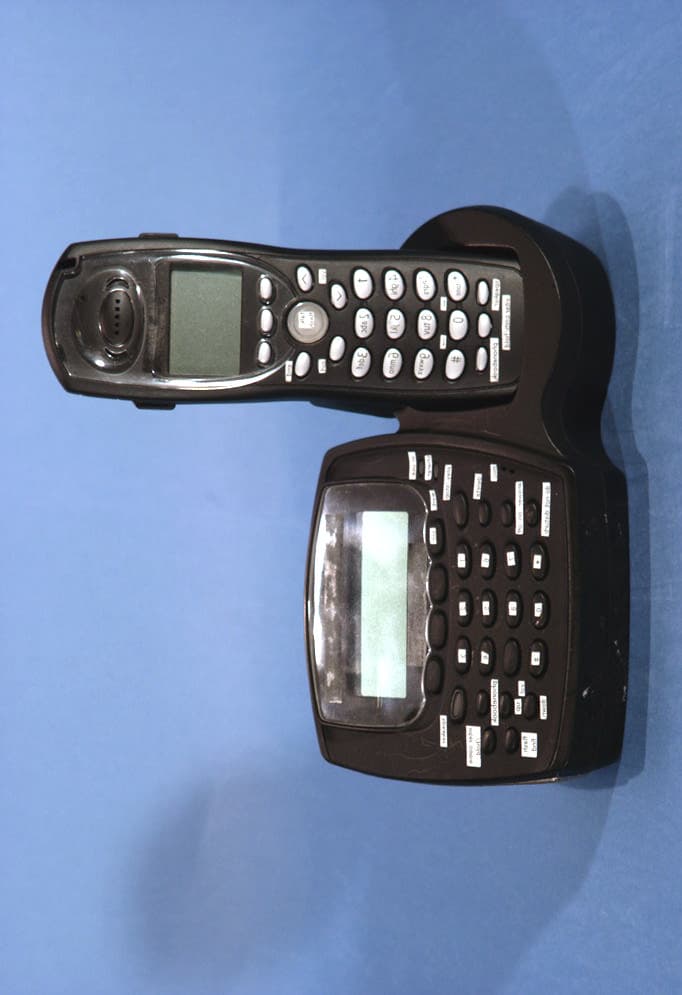
Click to zoom
Application Details
- Equipment Class
- DTS - Digital Transmission System
- Date of Grant
- Jan 08, 2004
- Application Purpose
- Original Equipment
- Date of Application
- Nov 04, 2003
- Equipment Note
- 5.8 GHz DSS Cordless Telephone
- Frequency Range
- 5741.05600000 - 5828.09600000
- Company
- Uniden America Corporation
- Country
- United States
Documents & Files
Document Text
Text extracted from the exhibit documents filed with the FCC. Open a document above to read the original.
Users Manual
[1] www.uniden.com WELCOME/FEATURES/TERMINOLOGY2 CONTROLS & FUNCTIONS4 DISPLAY AND ICONS6 SOFT KEY FUNCTION8 GETTING STARTED9 Setting up the Phone9 Mounting the Base Unit on a Wall13 Main the Menu Options15 Setting Menu Options17 BASICS33 Making and Receiving Calls33 Flash and Call Waiting34 Placing a Call on Hold34 Redialing a Call35 Adjusting the Ringer, and Earpiece and Speaker Volume36 Do Not Disturb (DND)36 Mute Microphone37 Tone Dialing Switch-over38 Traveling Out of Range38 Privacy Mode39 3 or 4-Way Conferencing39 PHONEBOOK41 Phonebook (Storing Phone Numbers, names, Distinctive Rings and Speed Dial)41 Chain Dialing42 Steps for Entering Names and Special Characters43 Viewing the Phonebook45 Making Calls Using the Phonebook46 Speed Dialing46 Editing or Erasing a Stored Name, Phone Number, Distinctive Ring and Speed Dial47 Copying Phonebook Locations48 CALLER ID49 Caller ID and CIDCW (Caller ID on Call Waiting)49 Viewing the Caller ID List50 Deleting a Caller ID Message51 Using the Caller ID Message List52 Call Waiting Deluxe Features54 THE INTEGRATED ANSWERING DEVICE55 The Integrated Telephone Answering Device55 Turning the Answering System On/Off56 Setting your outgoing message (Greeting)56 Using the Answering Setup Menu57 New Message LED57 Using your Answering System58 Remote Operation62 EXPANDING YOUR PHONE66 Expanding Your Phone66 Connecting the Charger66 Register the Handset67 Using the DirectLink Mode68 Intercom/Call Transfer Feature69 ADDITIONAL INFORMATION72 Changing the Digital Security Code72 Find Handset72 Installing the Beltclip72 Headset Installation73 Note on Power Sources73 Maintenance74 General Information75 TROUBLESHOOTING76 Liquid Damage79 PRECAUTIONS & WARRANTY80 I.C. NOTICE82 MEMORY LIST83 INDEX85 REMOTE OPERATION CARD86 MAIN MENU FLOW CHART88 Contents [2] WELCOME/FEATURES/TERMINOLOGY www.uniden.com Congratulations on your purchase of the Uniden Multi-Handset Cordless System telephone. This unit is different from conventional cordless telephones. When the base unit is connected to AC power and a telephone line, it can support up to 10 handsets. You can now place a fully-featured cordless handset anywhere in your home or office where AC power is available to connect the handset chargers. Extra handsets also allow you to establish a 4-way conference call among 2 handsets, the base speakerphone, and an outside line. Note: Some illustrations in this manual may differ from the actual unit for explanation purposes. As an Energy Star £ Partner, Uniden has determined that this product or product models meets the Energy Star £ guidelines for energy efficiency. Energy Star £ is a U.S. registered mark. • 5.8GHz Digital Expandable • Integrated Answering Device • Dual Keypad with LCD Screen at Base • 10 Multi-Handset Expandability • Hands-Free Speakerphone in the Handset and Base • Caller ID/Caller ID on Call Waiting (subscribe through local telephone company) • Call Waiting Deluxe (subscribe through local telephone company) • 100 Programmable Memory Locations • Trilingual Display Options and Voice Prompts (English, French and Spanish) • Intercom/Call Transfer Between Handsets • 20 Distinctive Ring Options (10 ringer tones and 10 melody ringers) • Mute and Hold Features • Do Not Disturb (DND) Feature •DirectLink¥ Mode • Room/Baby Monitoring • Battery Level Indicator • Clock Display •Animation Displays WELCOME/ FEATURES/ Welcome Features WELCOME/FEATURES/TERMINOLOGY [3] www.uniden.com This series features AutoTalk¥ and AutoStandby¥. AutoTalk allows you to answer a call by just removing the handset from the cradle so you don't have to waste time pushing buttons. AutoStandby allows you to hang up by simply returning the handset to the cradle. To protect you against mis-billed calls that might result from your phone being activated by other equipment, this series has Random Code¥ digital security, which automatically selects one of over approx. 65,000 digital security codes for the handset and base. Digital Spread Spectrum Technology uses a wider frequency band than standard digital transmissions. The result is a more secure conversation with the clarity of digital sound, extended range, and minimal interference from other cordless phones. IntegriSound¥ Built in sound quality which provides lifelike conversations. WithDirectLink¥ mode, you can use 2 or more handsets as radio tranceivers (walkie-talkies). Be sure to visit our web site: www.uniden.com Uniden £ is a registered trademark of Uniden America Corporation. AutoTalk, AutoStandby, DirectLink, IntegriSound and Random Code are trademarks of Uniden America. Terminology •Standby Mode - The handset is not in use, and talk/flash has not been pressed. No dial tone is present. •Talk Mode -The handset is not in the cradle, and talk/flash or speaker has been pressed, enabling a dial tone. 6CNM appears on the display. WELCOME/ FEATURES/ [4] CONTROLS & FUNCTIONSwww.uniden.com Controls & Functions 1. Handset Antenna 2. Beltclip Hole 3. Speaker Phone Speaker and Ringer 4. Handset Battery Compartment 5. New Message LED 6. Handset Earpiece 7. LCD Display 8.Soft Keys (P. 8) 9./vol and ∧/∨ (P. 36 & 17) 10. * /tone/< (P. 38 & 43) 11.speaker (P. 33) 12.intcom/hold (P. 69 & 34) 13.Headset Jack Cover 14.talk/flash (P. 33 & 34) 15.end (P. 33) 16.cid (Caller ID) (P. 50) 17.#/> (P. 43) 18.phonebook (P. 41) 19.Handset Microphone 20.Handset Charging Contacts 2 1 4 3 5 6 7 8 9 10 11 12 19 20 14 17 18 15 16 13 Play Skip Stop Delete Repeat Handset Remote Operation CONTROLS & FUNCTIONS CONTROLS & FUNCTIONS [5]www.uniden.com 44 46 45 23 24 25 2133 34 36 35 31 41 403029282726 42 432232 38 39 37 21. In use LED 22. play/stop (P. 58) 23.cid/exit (P. 50) 24. Charge LED 25. Base Charging Contacts 26.delete message (P. 59) 27.mic (microphone) 28. answer on/off (P. 56) 29.do not disturb (P. 36)/DND LED 30. tone (P. 38) 31. Message Counter Display (P. 8) 32.Soft Keys 33. Base Speaker 34.speaker/speaker LED (P. 33) 35.phonebook (P. 41) 36. intercom/hold Key (P. 69 …
Text truncated - open the document above for the full version.
Cover Letter(s)
January 6, 2004 Federal Communications Commission Equipment Approval Services 7435 Oakland Mills Road Columbia, MD 21046 Attn: Mr. Andy Leimer SUBJECT: Uniden Corporation FCC ID: AMWUP717 731 Confirmation No.: EA638039 Correspondence Reference No.: 26155 Request for Tech. Info.: 12/30/03 Dear Andy: Submitted herewith, on behalf of Uniden Corporation is an amendment provided in response to the request for technical information dated December 30, 2003. 1. Please find attached the revised SAR cover page indicating the correct type of device. 2. Please find attached the revised page 7 of the SAR report with the corrected body tissue recipe. 3. The SAR testing was conducted with the new SPEAG probe which is less than 6 mm in diameter. Please find attached page 5 of the SAR report with the probe specifications. 4. Please find attached the revised uncertainty budget. 5. Please find attached the probe calibration. 6. The basis for the dipole target is from SPEAG and is included in the dipole validation data in the SAR test report. 7. Please find attached the print out of the SAR liquid dielectric test system. We trust this information is sufficient to resolve FCC questions in this application. If you have any further questions, please do not hesitate to contact us. cc: Uniden Corporation
External Photos
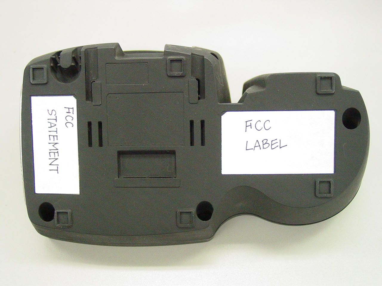
UNIDEN FCC ID: AMWUP717 EUT Photographs © 2003 PCTEST Lab. 5.8GHz Cordless Phone Model: TRU8886 UNIDEN FCC ID: AMWUP717 EUT Photographs © 2003 PCTEST Lab. 5.8GHz Cordless Phone Model: TRU8886 UNIDEN FCC ID: AMWUP717 EUT Photographs © 2003 PCTEST Lab. 5.8GHz Cordless Phone Model: TRU8886 UNIDEN FCC ID: AMWUP717 EUT Photographs © 2003 PCTEST Lab. 5.8GHz Cordless Phone Model: TRU8886 UNIDEN FCC ID: AMWUP717 EUT Photographs © 2003 PCTEST Lab. 5.8GHz Cordless Phone Model: TRU8886 UNIDEN FCC ID: AMWUP717 EUT Photographs © 2003 PCTEST Lab. 5.8GHz Cordless Phone Model: TRU8886 UNIDEN FCC ID: AMWUP717 EUT Photographs © 2003 PCTEST Lab. 5.8GHz Cordless Phone Model: TRU8886 UNIDEN FCC ID: AMWUP717 EUT Photographs © 2003 PCTEST Lab. 5.8GHz Cordless Phone Model: TRU8886 UNIDEN FCC ID: AMWUP717 EUT Photographs © 2003 PCTEST Lab. 5.8GHz Cordless Phone Model: TRU8886 UNIDEN FCC ID: AMWUP717 EUT Photographs © 2003 PCTEST Lab. 5.8GHz Cordless Phone Model: TRU8886 UNIDEN FCC ID: AMWUP717 EUT Photographs © 2003 PCTEST Lab. 5.8GHz Cordless Phone Model: TRU8886 UNIDEN FCC ID: AMWUP717 EUT Photographs © 2003 PCTEST Lab. 5.8GHz Cordless Phone Model: TRU8886
Internal Photos
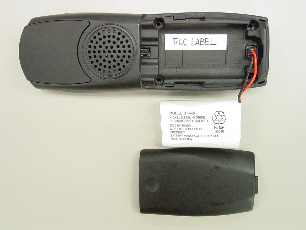
UNIDEN FCC ID: AMWUP717 EUT Photographs © 2003 PCTEST Lab. 5.8GHz Cordless Phone Model: TRU8886 UNIDEN FCC ID: AMWUP717 EUT Photographs © 2003 PCTEST Lab. 5.8GHz Cordless Phone Model: TRU8886 UNIDEN FCC ID: AMWUP717 EUT Photographs © 2003 PCTEST Lab. 5.8GHz Cordless Phone Model: TRU8886 UNIDEN FCC ID: AMWUP717 EUT Photographs © 2003 PCTEST Lab. 5.8GHz Cordless Phone Model: TRU8886 UNIDEN FCC ID: AMWUP717 EUT Photographs © 2003 PCTEST Lab. 5.8GHz Cordless Phone Model: TRU8886 UNIDEN FCC ID: AMWUP717 EUT Photographs © 2003 PCTEST Lab. 5.8GHz Cordless Phone Model: TRU8886 UNIDEN FCC ID: AMWUP717 EUT Photographs © 2003 PCTEST Lab. 5.8GHz Cordless Phone Model: TRU8886 UNIDEN FCC ID: AMWUP717 EUT Photographs © 2003 PCTEST Lab. 5.8GHz Cordless Phone Model: TRU8886 UNIDEN FCC ID: AMWUP717 EUT Photographs © 2003 PCTEST Lab. 5.8GHz Cordless Phone Model: TRU8886 UNIDEN FCC ID: AMWUP717 EUT Photographs © 2003 PCTEST Lab. 5.8GHz Cordless Phone Model: TRU8886 UNIDEN FCC ID: AMWUP717 EUT Photographs © 2003 PCTEST Lab. 5.8GHz Cordless Phone Model: TRU8886 UNIDEN FCC ID: AMWUP717 EUT Photographs © 2003 PCTEST Lab. 5.8GHz Cordless Phone Model: TRU8886 UNIDEN FCC ID: AMWUP717 EUT Photographs © 2003 PCTEST Lab. 5.8GHz Cordless Phone Model: TRU8886 UNIDEN FCC ID: AMWUP717 EUT Photographs © 2003 PCTEST Lab. 5.8GHz Cordless Phone Model: TRU8886 UNIDEN FCC ID: AMWUP717 EUT Photographs © 2003 PCTEST Lab. 5.8GHz Cordless Phone Model: TRU8886
RF Exposure Info
UNIDEN FCC ID: AMWUP717 EUT Photographs © 2003 PCTEST Lab. 5.8GHz Cordless Phone Model: TRU8886 UNIDEN FCC ID: AMWUP717 EUT Photographs © 2003 PCTEST Lab. 5.8GHz Cordless Phone Model: TRU8886 UNIDEN FCC ID: AMWUP717 EUT Photographs © 2003 PCTEST Lab. 5.8GHz Cordless Phone Model: TRU8886 UNIDEN FCC ID: AMWUP717 EUT Photographs © 2003 PCTEST Lab. 5.8GHz Cordless Phone Model: TRU8886 UNIDEN FCC ID: AMWUP717 EUT Photographs © 2003 PCTEST Lab. 5.8GHz Cordless Phone Model: TRU8886 UNIDEN FCC ID: AMWUP717 EUT Photographs © 2003 PCTEST Lab. 5.8GHz Cordless Phone Model: TRU8886 UNIDEN FCC ID: AMWUP717 EUT Photographs © 2003 PCTEST Lab. 5.8GHz Cordless Phone Model: TRU8886 UNIDEN FCC ID: AMWUP717 EUT Photographs © 2003 PCTEST Lab. 5.8GHz Cordless Phone Model: TRU8886 UNIDEN FCC ID: AMWUP717 EUT Photographs © 2003 PCTEST Lab. 5.8GHz Cordless Phone Model: TRU8886 UNIDEN FCC ID: AMWUP717 EUT Photographs © 2003 PCTEST Lab. 5.8GHz Cordless Phone Model: TRU8886 UNIDEN FCC ID: AMWUP717 EUT Photographs © 2003 PCTEST Lab. 5.8GHz Cordless Phone Model: TRU8886 UNIDEN FCC ID: AMWUP717 EUT Photographs © 2003 PCTEST Lab. 5.8GHz Cordless Phone Model: TRU8886 UNIDEN FCC ID: AMWUP717 EUT Photographs © 2003 PCTEST Lab. 5.8GHz Cordless Phone Model: TRU8886 UNIDEN FCC ID: AMWUP717 EUT Photographs © 2003 PCTEST Lab. 5.8GHz Cordless Phone Model: TRU8886 UNIDEN FCC ID: AMWUP717 EUT Photographs © 2003 PCTEST Lab. 5.8GHz Cordless Phone Model: TRU8886
RF Exposure Info
PCTEST ENGINEERING LABORATORY, INC. 6660 – B Dobbin Road • Columbia, MD 21045 • USA Telephone 410.290.6652 / Fax 410.290.6654 http://www.pctestlab.com (email: [email protected]) CERTIFICATE OF COMPLIANCE (SAR EVALUATION) PCTEST SAR REPORT FCC Measurement Report Reviewed by: Quality Manager SAR Filename: SAR-230924533.AMW Test Dates: October 15-22, 2003 Phone Type: 5.8 GHz Cordless Phone FCC ID: AMWUP717 Page 1 of 29 © 2003 PCTEST Engineering Laboratory, Inc APPLICANT NAME & ADDRESS: DATE & LOCATION OF TESTING: Uniden Engineering Services Dates of Tests: October 15-22, 2003 216 John Street, P.O. Box 580 Test Report S/N: SAR.230924533.AMW Lake City, SC 92560-0580 Test Site: PCTEST Lab, Columbia MD FCC ID: AMWUP717 APPLICANT: UNIDEN ENGINEERING SERVICES EUT Type: Tri-Mode Dual-Band Analog/PCS Phone (AMPS/CDMA) Tx Frequency: 5741 – 5828 MHz Rx Frequency: 5741 – 5828 MHz Max. RF Output Power: 18.67 dBm EIRP (HS), 24.18 dBm EIRP (BASE) Max. SAR Measurement: 0.099 W/kg Head SAR; 0.571 W/kg Body SAR; Trade Name/Model(s): TRU8885 FCC Classification: FCC Part 15 Digital Transmission System (DTS) FCC Rule Part(s): §2.1093; FCC/OET Bulletin 65 Supplement C [July 2001] Application Type: Certification Test Device Serial No.: identical prototype [S/N: 2] This wireless portable device has been shown to be capable of compliance for localized specific absorption rate (SAR) for uncontrolled environment/general population exposure limits specified in ANSI/IEEE Std. C95.1-1992 and had been tested in accordance with the measurement procedures specified in FCC/OET Bulletin 65 Supplement C (2001) and IEEE Std. 1528-200X (Draft 6.5, January 15, 2002). I attest to the accuracy of data. All measurements reported herein were performed by me or were made under my supervision and are correct to the best of my knowledge and belief. I assume full responsibility for the completeness of these measurements and vouch for the qualifications of all persons taking them. Grant Conditions: Output power is EIRP. This transmitter has been tested for SAR compliance for head and body- worn configurations. SAR compliance for body-worn operating configurations is limited to the specific belt-clip tested for this filing. Users must be informed of the operating requirements for satisfying body-worn RF exposure compliance. PCTEST certifies that no party to this application has been denied the FCC benefits pursuant to Section 5301 of the Anti-Drug Abuse Act of 1988, 21 U.S.C. 862. SAR.230924533.AMW PCTEST SAR REPORT FCC Measurement Report Reviewed by: Quality Manager SAR Filename: SAR-230924533.AMW Test Dates: October 15-22, 2003 Phone Type: 5.8 GHz Cordless Phone FCC ID: AMWUP717 Page 2 of 29 © 2003 PCTEST Engineering Laboratory, Inc TABLE OF CONTENTS 1. INTRODUCTION / SAR DEFINITION.................................................................................3 2. SAR MEASUREMENT SETUP.............................................................................................4 3. DASY4 E-FIELD PROBE SYSTEM........................................................................................5 4. Probe Calibration Process..................................................................................................6 5. PHANTOM & EQUIVALENT TISSUES................................................................................7 6. TEST SYSTEM SPECIFICATIONS.........................................................................................8 7. DOSIMETRIC ASSESSMENT & PHANTOM SPECS...............................................................9 8. DEFINITION OF REFERENCE POINTS..............................................................................10 9. TEST CONFIGURATION POSITIONS...............................................................................11 10. ANSI/IEEE C95.1 - 1992 RF EXPOSURE LIMITS.................................................................14 11. MEASUREMENT UNCERTAINTIES...................................................................................15 12. SYSTEM VERIFICATION..................................................................................................16 13. SAR TEST DATA SUMMARY...........................................................................................17 15. SAR TEST EQUIPMENT...................................................................................................23 16. CONCLUSION...............................................................................................................24 17. REFERENCES..................................................................................................................25 EXHIBIT A: SAR TEST DATA........................................................................................26 EXHIBIT B: SAR TEST SETUP PHOTOGRAPHS.................................................................27 EXHIBIT C: DIPOLE VALIDATION.................................................................................28 EXHIBIT D: PROBE CALIBRATION DATA.......................................................................29 PCTEST SAR REPORT FCC Measurement Report Reviewed by: Quality Manager SAR Filename: SAR-230924533.AMW Test Dates: October 15-22, 2003 Phone Type: 5.8 GHz Cordless Phone FCC ID: AMWUP717 Page 3 of 29 © 2003 PCTEST Engineering Laboratory, Inc 1. INTRODUCTION / SAR DEFINITION The FCC has adopted the guidelines for evaluating the environmental effects of radiofrequency radiation in ET Docket 93-62 on Aug. 6, 1996 to protect the public and workers from the potential hazards of RF emissions due to FCC-regulated portable devices.[1] The safety limits used for the environmental evaluation measurements are based on the criteria published by the American National Standards Institute (ANSI) for localized specific absorption rate (SAR) in IEEE/ANSI C95.1-1992 Standard for Safety Levels with Respect to Human Exposure to Radio Frequency Electromagnetic Fields, 3 kHz to 300 GHz. (c) 1992 by the Institute o…
Text truncated - open the document above for the full version.
RF Exposure Info
PCTEST ENGINEERING LABORATORY, INC. DUT: TRU8885; Type: Handset for Uniden 5.8GHz Cordless Phone Communication System: 5.8GHz TDMA Cordless; Frequency: 5782.02 MHz;Duty Cycle: 1:4 Medium: 5800 Brain ( σ = 5.22 mho/m, ε r = 36.13, ρ = 1000 kg/m 3 ) Phantom section: Right Section Test Date: 10-13-2003; Ambient Temp: 23.2°C; Tissue Temp: 20.4°C Probe: ES3DV2 - SN3022; ConvF(2.15, 2.15, 2.15); Calibrated: 9/23/2003 Sensor-Surface: 3mm (Mechanical Surface Detection) Electronics: DAE3 SN330; Calibrated: 12/1/2002 Phantom: SAM 12b; Type: SAM 4.0; Serial: TP:1197 Measurement SW: DASY4, V4.1 Build 47; Postprocessing SW: SEMCAD, V1.8 Build 62 Ch.17, Touch Area Scan (81x181x1): Measurement grid: dx=10mm, dy=10mm Zoom Scan (7x7x8)/Cube 0: Measurement grid: dx=4.3mm, dy=4.3mm, dz=3mm Peak SAR (extrapolated) = 0.422 W/kg SAR(1 g) = 0.043 mW/g; SAR(10 g) = 0.016 mW/g Reference Value = 1.88 V/m 0 dB = 0.057mW/g PCTEST ENGINEERING LABORATORY, INC. DUT: TRU8885; Type: Handset for Uniden 5.8GHz Cordless Phone Communication System: 5.8GHz TDMA Cordless; Frequency: 5741.06 MHz;Duty Cycle: 1:4 Medium: 5800 Brain ( σ = 5.22 mho/m, ε r = 36.13, ρ = 1000 kg/m 3 ) Phantom section: Right Section Test Date: 10-13-2003; Ambient Temp: 23.2°C; Tissue Temp: 20.4°C Probe: ES3DV2 - SN3022; ConvF(2.15, 2.15, 2.15); Calibrated: 9/23/2003 Sensor-Surface: 3mm (Mechanical Surface Detection) Electronics: DAE3 SN330; Calibrated: 12/1/2002 Phantom: SAM 12b; Type: SAM 4.0; Serial: TP:1197 Measurement SW: DASY4, V4.1 Build 47; Postprocessing SW: SEMCAD, V1.8 Build 62 Ch.01, Tilt Area Scan (81x181x1): Measurement grid: dx=10mm, dy=10mm Zoom Scan (7x7x8)/Cube 0: Measurement grid: dx=4.3mm, dy=4.3mm, dz=3mm Peak SAR (extrapolated) = 1.08 W/kg SAR(1 g) = 0.099 mW/g; SAR(10 g) = 0.038 mW/g Reference Value = 1.22 V/m 0 dB = 0.129mW/g PCTEST ENGINEERING LABORATORY, INC. DUT: TRU8885; Type: Handset for Uniden 5.8GHz Cordless Phone Communication System: 5.8GHz TDMA Cordless; Frequency: 5741.06 MHz;Duty Cycle: 1:4 Medium: 5800 Brain ( σ = 5.22 mho/m, ε r = 36.13, ρ = 1000 kg/m 3 ) Phantom section: Left Section Test Date: 10-14-2003; Ambient Temp: 22.4°C; Tissue Temp: 20.6°C Probe: ES3DV2 - SN3022; ConvF(2.15, 2.15, 2.15); Calibrated: 9/23/2003 Sensor-Surface: 3mm (Mechanical Surface Detection) Electronics: DAE3 SN330; Calibrated: 12/1/2002 Phantom: SAM 12b; Type: SAM 4.0; Serial: TP:1197 Measurement SW: DASY4, V4.1 Build 47; Postprocessing SW: SEMCAD, V1.8 Build 62 Ch.01, Touch Area Scan (81x181x1): Measurement grid: dx=10mm, dy=10mm Zoom Scan (7x7x8)/Cube 0: Measurement grid: dx=4.3mm, dy=4.3mm, dz=3mm Peak SAR (extrapolated) = 2.91 W/kg SAR(1 g) = 0.053 mW/g; SAR(10 g) = 0.015 mW/g Reference Value = 1.59 V/m 0 dB = 0.058mW/g PCTEST ENGINEERING LABORATORY, INC. DUT: TRU8885; Type: Handset for Uniden 5.8GHz Cordless Phone Communication System: 5.8GHz TDMA Cordless; Frequency: 5741.06 MHz;Duty Cycle: 1:4 Medium: 5800 Brain ( σ = 5.22 mho/m, ε r = 36.13, ρ = 1000 kg/m 3 ) Phantom section: Left Section Test Date: 10-14-2003; Ambient Temp: 22.4°C; Tissue Temp: 20.6°C Probe: ES3DV2 - SN3022; ConvF(2.15, 2.15, 2.15); Calibrated: 9/23/2003 Sensor-Surface: 3mm (Mechanical Surface Detection) Electronics: DAE3 SN330; Calibrated: 12/1/2002 Phantom: SAM 12b; Type: SAM 4.0; Serial: TP:1197 Measurement SW: DASY4, V4.1 Build 47; Postprocessing SW: SEMCAD, V1.8 Build 62 Ch.01, Tilt Area Scan (81x181x1): Measurement grid: dx=10mm, dy=10mm Zoom Scan (7x7x8)/Cube 0: Measurement grid: dx=4.3mm, dy=4.3mm, dz=3mm Peak SAR (extrapolated) = 1.14 W/kg SAR(1 g) = 0.081 mW/g; SAR(10 g) = 0.024 mW/g Reference Value = 2.01 V/m 0 dB = 0.089mW/g PCTEST ENGINEERING LABORATORY, INC. DUT: TRU8885; Type: Handset for Uniden 5.8GHz Cordless Phone Communication System: 5.8GHz TDMA Cordless; Frequency: 5741.06 MHz;Duty Cycle: 1:4 Medium: 5800 Muscle ( σ = 6.16 mho/m, ε r = 47.84, ρ = 1000 kg/m 3 ) Phantom section: Flat Section; Space: 0.0 cm Test Date: 10-15-2003; Ambient Temp: 22.6°C; Tissue Temp: 20.2°C Probe: ES3DV2 - SN3022; ConvF(1.57, 1.57, 1.57); Calibrated: 9/23/2003 Sensor-Surface: 3mm (Mechanical Surface Detection) Electronics: DAE3 SN330; Calibrated: 12/1/2002 Phantom: SAM 12b; Type: SAM 4.0; Serial: TP:1197 Measurement SW: DASY4, V4.1 Build 47; Postprocessing SW: SEMCAD, V1.8 Build 62 Ch.01 Area Scan (81x181x1): Measurement grid: dx=10mm, dy=10mm Zoom Scan (7x7x8)/Cube 0: Measurement grid: dx=4.3mm, dy=4.3mm, dz=3mm Peak SAR (extrapolated) = 2.04 W/kg SAR(1 g) = 0.571 mW/g; SAR(10 g) = 0.237 mW/g Reference Value = 2.59 V/m 0 dB = 0.777mW/g PCTEST ENGINEERING LABORATORY, INC. DUT: TRU8885; Type: Handset for Uniden 5.8GHz Cordless Phone Communication System: 5.8GHz TDMA Cordless; Frequency: 5741.06 MHz;Duty Cycle: 1:4 Medium: 5800 Brain ( σ = 5.22 mho/m, ε r = 36.13, ρ = 1000 kg/m 3 ) Phantom section: Right Section Test Date: 10-13-2003; Ambient Temp: 23.2°C; Tissue Temp: 20.4°C Probe: ES3DV2 - SN3022; ConvF(2.15, 2.15, 2.15); Calibrated: 9/23/2003 Sensor-Surface: 3mm (Mechanical Surface Detection) Electronics: DAE3 SN330; Calibrated: 12/1/2002 Phantom: SAM 12b; Type: SAM 4.0; Serial: TP:1197 Measurement SW: DASY4, V4.1 Build 47; Postprocessing SW: SEMCAD, V1.8 Build 62 Ch.01, Tilt Area Scan (81x181x1): Measurement grid: dx=10mm, dy=10mm Zoom Scan (7x7x8)/Cube 0: Measurement grid: dx=4.3mm, dy=4.3mm, dz=3mm Peak SAR (extrapolated) = 1.08 W/kg SAR(1 g) = 0.099 mW/g; SAR(10 g) = 0.038 mW/g Reference Value = 1.22 V/m PCTEST ENGINEERING LABORATORY, INC. DUT: TRU8885; Type: Handset for Uniden 5.8GHz Cordless Phone Communication System: 5.8GHz TDMA Cordless; Frequency: 5741.06 MHz;Duty Cycle: 1:4 Medium: 5800 Muscle ( σ = 6.16 mho/m, ε r = 47.84, ρ = 1000 kg/m 3 ) Phantom section: Flat Section; Space: 0.0 cm Test Date: 10-15-2003; Ambient Temp: 22.6°C; Tissue Temp: 20.2°C Probe: ES3DV2 - SN3022; ConvF(1.57, 1.57, 1.57); Calibrated: 9/23/2003 Sensor-Surface: 3mm (Mechanical Surface Detection) Electronics: DAE3 SN330; Calibrated: 12/1/2002 Phantom: SAM 12b; Type: SAM 4.0; Seri…
Text truncated - open the document above for the full version.
RF Exposure Info
ES3DV2-SN:3022 Page 1 of 2 December 3, 2003 Additional Conversion Factors for Dosimetric E-Field Probe Type: Serial Number: Place of Assessment: Date of Assessment: Probe Calibration Date: Schmid & Partner Engineering AG hereby certifies that conversion factor(s) of this probe have been evaluated on the date indicated above. The assessment was performed using the FDTD numerical code SEMCAD of Schmid & Partner Engineering AG. Since the evaluation is coupled with measured conversion factors, it has to be recalculated yearly, i.e., following the re-calibration schedule of the probe. The uncertainty of the numerical assessment is based on the extrapolation from measured value at 900 MHz or at 1800 MHz. Assessed by: ES3DV2 3022 Zurich December 3, 2003 September 23, 2003 ES3DV2-SN:3022 Page 2 of 2 December 3, 2003 Dosimetric E-Field Probe ES3DV2 SN:3022 Conversion factor (± standard deviation) 1950 MHz ConvF 4.7 ± 9.5% e r = 40.0 ± 5% s = 1.40 ± 5% mho/m (head tissue) 1950 MHz ConvF 4. 3 ± 9.5% e r = 53.3 ± 5% s = 1.52 ± 5% mho/m (body tissue) ES3DV2-SN:3022Page 1 of 2November 28, 2003 Additional Conversion Factors for Dosimetric E-Field Probe Type: Serial Number: Place of Assessment: Date of Assessment: Probe Calibration Date: Schmid & Partner Engineering AG hereby certifies that conversion factor(s) of this probe have been evaluated on the date indicated above. The assessment was performed using the FDTD numerical code SEMCAD of Schmid & Partner Engineering AG. Since the evaluation is coupled with measured conversion factors, it has to be recalculated yearly, i.e., following the re-calibration schedule of the probe. The uncertainty of the numerical assessment is based on the extrapolation from measured value at 900 MHz or at 1800 MHz. Assessed by: ES3DV2 3022 Zurich November 28, 2003 September 23, 2003 ES3DV2-SN:3022Page 2 of 2November 28, 2003 Dosimetric E-Field Probe ES3DV2 SN:3022 Conversion factor (± standard deviation) 1600 MHzConvF5.2 ± 8% e r =40.3 ± 5% s =1.29 ± 5% mho/m (head tissue) 1600 MHzConvF4.9 ± 8% e r =53.8 ± 5% s =1.40 ± 5% mho/m (body tissue) ES3DV2-SN:3022Page 1 of 2December 9, 2003 Additional Conversion Factors for Dosimetric E-Field Probe Type: Serial Number: Place of Assessment: Date of Assessment: Probe Calibration Date: Schmid & Partner Engineering AG hereby certifies that conversion factor(s) of this probe have been evaluated on the date indicated above. The assessment was performed using the FDTD numerical code SEMCAD of Schmid & Partner Engineering AG. Since the evaluation is coupled with measured conversion factors, it has to be recalculated yearly, i.e., following the re-calibration schedule of the probe. The uncertainty of the numerical assessment is based on the extrapolation from measured value at 900 MHz or at 1800 MHz. Assessed by: ES3DV2 3022 Zurich December 9, 2003 September 23, 2003 ES3DV2-SN:3022Page 2 of 2December 9, 2003 Dosimetric E-Field Probe ES3DV2 SN:3022 Conversion factor (± standard deviation) 2140 MHzConvF4.5 ± 8% e r =39.8 ± 5% s =1.49 ± 5% mho/m (brain tissue)
RF Exposure Info
PCTEST ENGINEERING LABORATORY, INC. 6660 – B Dobbin Road • Columbia, MD 21045 • USA Telephone 410.290.6652 / Fax 410.290.6654 http://www.pctestlab.com (email: [email protected]) CERTIFICATE OF COMPLIANCE (SAR EVALUATION) PCTEST SAR REPORT FCC Measurement Report Reviewed by: Quality Manager SAR Filename: SAR-230924533-R1.AMW Test Dates: October 15-22, 2003 Phone Type: 5.8 GHz Cordless Phone FCC ID: AMWUP717 Page 1 of 29 © 2003 PCTEST Engineering Laboratory, Inc APPLICANT NAME & ADDRESS: DATE & LOCATION OF TESTING: Uniden Engineering Services Dates of Tests: October 15-22, 2003 216 John Street, P.O. Box 580 Test Report S/N: SAR.230924533-R1.AMW Lake City, SC 92560-0580 Test Site: PCTEST Lab, Columbia MD FCC ID: AMWUP717 APPLICANT: UNIDEN ENGINEERING SERVICES EUT Type: 5.8 GHz Cordless Phone Tx Frequency: 5741 – 5828 MHz Rx Frequency: 5741 – 5828 MHz Max. RF Output Power: 18.67 dBm EIRP (HS), 24.18 dBm EIRP (BASE) Max. SAR Measurement: 0.099 W/kg Head SAR; 0.571 W/kg Body SAR; Trade Name/Model(s): TRU8885 FCC Classification: FCC Part 15 Digital Transmission System (DTS) FCC Rule Part(s): §2.1093; FCC/OET Bulletin 65 Supplement C [July 2001] Application Type: Certification Test Device Serial No.: identical prototype [S/N: 2] This wireless portable device has been shown to be capable of compliance for localized specific absorption rate (SAR) for uncontrolled environment/general population exposure limits specified in ANSI/IEEE Std. C95.1-1992 and had been tested in accordance with the measurement procedures specified in FCC/OET Bulletin 65 Supplement C (2001) and IEEE Std. 1528-200X (Draft 6.5, January 15, 2002). I attest to the accuracy of data. All measurements reported herein were performed by me or were made under my supervision and are correct to the best of my knowledge and belief. I assume full responsibility for the completeness of these measurements and vouch for the qualifications of all persons taking them. Grant Conditions: Output power is EIRP. This transmitter has been tested for SAR compliance for head and body- worn configurations. SAR compliance for body-worn operating configurations is limited to the specific belt-clip tested for this filing. Users must be informed of the operating requirements for satisfying body-worn RF exposure compliance. PCTEST certifies that no party to this application has been denied the FCC benefits pursuant to Section 5301 of the Anti-Drug Abuse Act of 1988, 21 U.S.C. 862. PCTEST SAR REPORT FCC Measurement Report Reviewed by: Quality Manager SAR Filename: SAR-230924533-R1.AMW Test Dates: October 15-22, 2003 Phone Type: 5.8 GHz Cordless Phone FCC ID: AMWUP717 Page 5 of 29 © 2003 PCTEST Engineering Laboratory, Inc 3. DASY4 E-FIELD PROBE SYSTEM Probe Measurement System The SAR measurements were conducted with the dosimetric probe ET3DV6, designed in the classical triangular configuration [7] (see Fig. 3.2) and optimized for dosimetric evaluation. The probe is constructed using the thick film technique; with printed resistive lines on ceramic substrates. The probe is equipped with an optical multifiber line ending at the front of the probe tip (see Fig. 3.3). It is connected to the EOC box on the robot arm and provides an automatic detection of the phantom surface. Half of the fibers are connected to a pulsed infrared transmitter, the other half to a synchronized receiver. As the probe approaches the surface, the reflection from the surface produces a coupling from the transmitting to the receiving fibers. This reflection increases first during the approach, reaches maximum and then decreases. If the prob…
Text truncated - open the document above for the full version.
Contact Information
Applicant
Paul Roby
Test Firm
PCTEST Engineering Laboratory, Inc.Randy Ortanez
Technical Specifications
| # | Rule Parts | Frequency Range | Power Output |
|---|---|---|---|
| 2 | 15C | 5.74 GHz - 5.83 GHz | 73.40 mW |
Other Applications from Uniden America Corporation
AMWUA2405
Apr 15, 2026RADAR DETECTOR
Equipment Class
JBP - Part 15 Class B Computing Device PeripheralAMWUA2406
Apr 15, 2026RADAR DETECTOR
Equipment Class
JBP - Part 15 Class B Computing Device PeripheralAMWUA2402
Jul 23, 2024RADAR DETECTOR
Equipment Class
CRD - Part 15 Radar Detector
AMWUA2404
Feb 17, 2024Wi-Fi Bluetooth Combo Module
Equipment Class
DTS - Digital Transmission System
AMWUA2301
Feb 15, 2023RADAR DETECTOR
Equipment Class
CRD - Part 15 Radar Detector