AMWUT022PORTABLE FRS/GMRS RADIO
Uniden America Corporation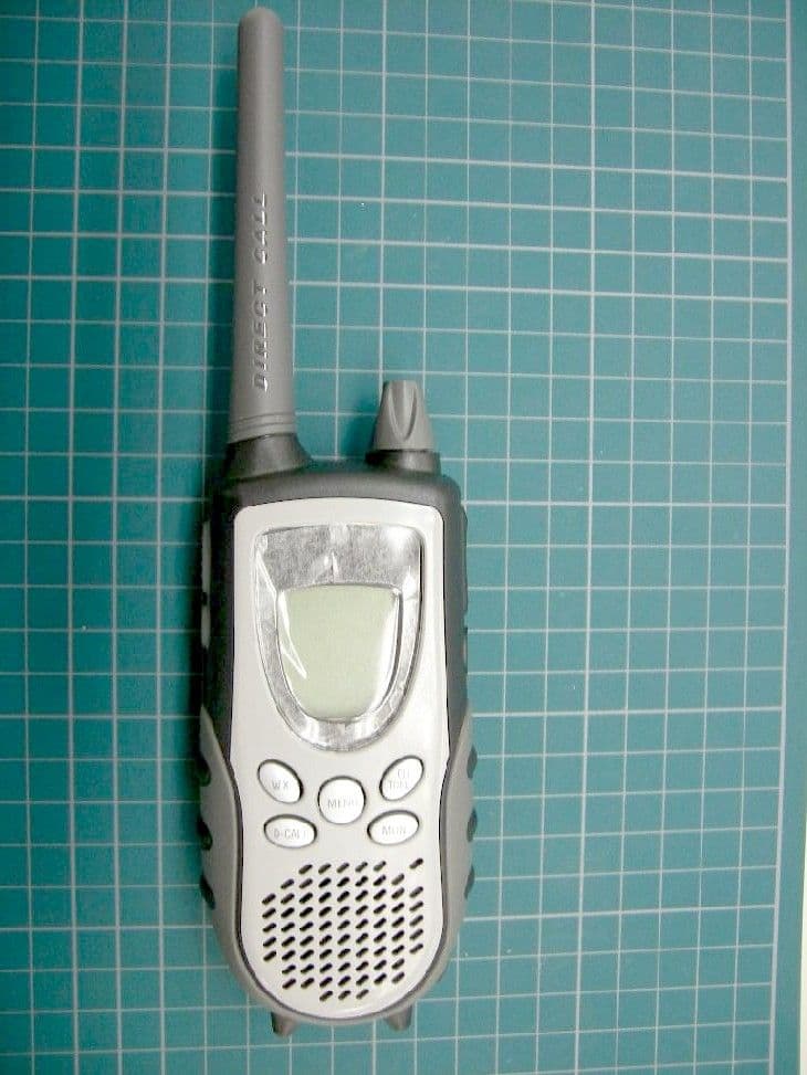
Click to zoom
Application Details
- Equipment Class
- FRF - Part 95 Family Radio Face Held Transmitter
- Date of Grant
- Jun 05, 2006
- Application Purpose
- Original Equipment
- Date of Application
- Jun 05, 2006
- Equipment Note
- PORTABLE FRS/GMRS RADIO
- Frequency Range
- 462.55000000 - 462.72500000
- Company
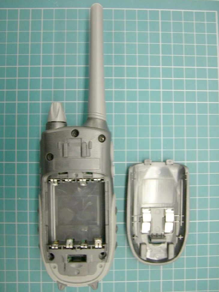
- Uniden America Corporation
- Country
- United States
Documents & Files
Document Text
Text extracted from the exhibit documents filed with the FCC. Open a document above to read the original.
Users Manual
Thank you for purchasing your 2-way radios from RadioShack . You can talk to others in the next room, next door, and around the neighborhood. Your radios transmit and receive General Mobile Radio Service (GMRS) and Family Radio Service (FRS) frequencies. 21-1936 18-mile GMRS/FRS 2-way radios with charger Your radio has 22 channels and 142 quiet codes. To talk to others, you must be on the same channel and quiet code if it is activated. To set a quiet code, turn off group mode. To select a channel and quiet code: 1. Press CH/TONE/SCN , and then repeatedly press U or V to select a channel (1-22). 2. Press CH / TONE/SCN . The quiet code number fl ashes. 3. Repeatedly press U or V to select a quiet code ( oFF or 1 - 142). 4. Press CH / TONE/SCN again. • Quiet codes limit authorized users and reduce interference. • Code oFF indicates that you have no quiet code selected. Your radio can receive a signal regardless of other radio settings. channel frequency chart Ch. Cross Ref. Ch. Cross Ref. 1 462.5625 FRS & GMRS 12 467.6625 FRS 2 462.5875 FRS & GMRS 13 467.6875 FRS 3 462.6125 FRS & GMRS 14 467.7125 FRS 4 462.6375 FRS & GMRS 15 462.5500 GMRS 5 462.6625 FRS & GMRS 16 462.5750 GMRS 6 462.6875 FRS & GMRS 17 462.6000 GMRS 7 462.7125 FRS & GMRS 18 462.6250 GMRS 8 467.5625 FRS 19 462.6500 GMRS 9 467.5875 FRS 20 462.6750 GMRS 10 467.6125 FRS 21 462.7000 GMRS 11 467.6375 FRS 22 462.7250 GMRS • Use FRS ( LO ) channels 8 - 14, with a range of up to 5 miles, for longer battery life. Use GMRS ( HI ) channels 1 - 7 and 15 - 22, with a range of up to 18 miles, for more power. • You can boost the typical range of GMRS channels only when operating on a Ni-MH battery pack. When you press BOOST while using alkaline batteries, TXHI appears instead of BOOS and the range is not boosted. This product is warranted by RadioShack against manufacturing defects in material and workmanship under normal use for one (1) year from the date of purchase from RadioShack company-owned stores and authorized RadioShack franchisees and dealers. For complete warranty details and exclusions, check with your local RadioShack store. RadioShack Customer Relations 300 RadioShack Circle Fort Worth, TX 76102 04/04 • Keep your radios dry; if they get wet, wipe them dry immediately. • Handle your radios carefully; do not drop them. • Wipe your radios with a damp cloth occasionally to keep them looking new. installing batteries To install the battery pack or AAA batteries (not included), remove the battery compartment cover, install the battery pack according to the label and replace the cover. • Dispose of old batteries promptly and properly. Do not burn or bury them. • Use only fresh batteries of the required size and recommended type. Do not mix batteries of different sizes or chemistries. • If you do not plan to use your radio for a month or more, remove the batteries. Batteries can leak chemicals that can damage electronic parts. charging your radiosBattery packs take about 16 hours to fully charge. When the battery is low, BATT appears and fl ashes. Recharge the battery pack. You can charge in one of two ways: using the cradle or your car adapter (not included). • Do not recharge alkaline batteries. • To prolong the life of your rechargeable batteries, always fully discharge your battery pack before recharging. • You cannot recharge AAA type rechargeable batteries. charging using the cradle 1. Plug the supplied AC adapter into the cradle and a standard wall outlet. 2. Turn off the radio and place in the charger.3. Charge the battery pack for 16 hours. (The indicator on the cradle lights while the radio is on the cradle even after the charging fi nishes.) Then remove the radio from the cradle after charging. using vehicle battery powerYou can charge the radio using a 9V, 210 mA DC adapter and a size H Adaptaplug T M TM adapter (neither supplied). Both are available at RadioShack . You must use a power adapter that supplies 9V DC and delivers at least 210 mA. Its center tip must be set to positive and its plug must fi t the radio’s DC 9V jack. Using an adapter that does not meet these speci fi cations could damage the radio or the adapter. 1. Turn off the radio.2. Insert the Adaptaplug into the adapter’s cord with center tips set to positive + . Then, insert the Adaptaplug into the radio’s 9V jack and plug the other end of the adapter into your vehicle’s power adapter socket. 3. Charge the battery pack for 16 hours until the display becomes blank. automatic power save feature After three seconds of inactivity, your radio switches to Power Save mode. The radio can still receive transmissions in this mode. attaching belt clips Attach each belt clip by sliding the belt clip down. To remove, lift the tab and slide the belt clip upward.making a call 1. Turn on the radio.2. Verify the person you wish to talk to is on the same channel. 3. Press PTT (push to talk) to talk, then release to listen. muting keystroke tones To mute the keystroke tones, press and hold D-CALL while turning on the radio. To reactivate the keystroke tones, turn the radio off. Then turn it back on while holding down D-CALL . activating roger beep A roger beep is sent to notify the end of a transmission. To activate the roger beep, press and hold U while turning on the radio. To deactivate the roger beep, turn the radio off. Then turn it back on while holding U . You can hear a sent roger beep when the keystroke tone feature is on. This radio operates on the General Mobile Radio Service (GMRS) frequencies when using Channels 1—7 and channels 15—22. You must have a GMRS license issued by the Federal Communications Commission to legally use these channels. For licensing information and application forms, visit the FCC online at: www.fcc.gov/wtb/uls or call the FCC hotline at 1-800-418-3676. If you have any questions, you can contact the FCC direct at 1-888-225-5322.No license is required for operation on channels 8-14 or operation on any channel in Canada. Channels .........…
Text truncated - open the document above for the full version.
Attestation Statements
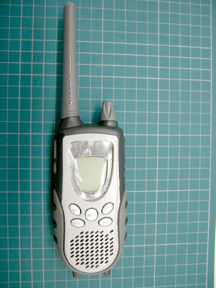
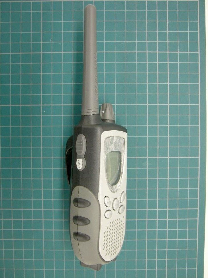
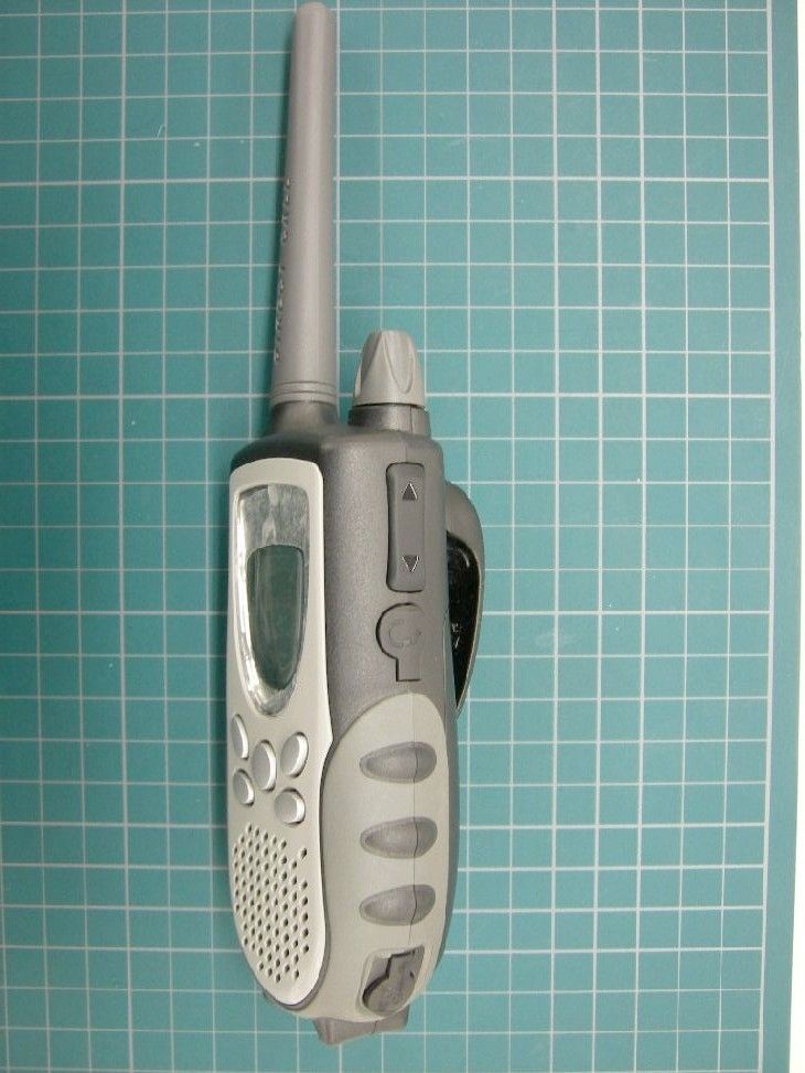
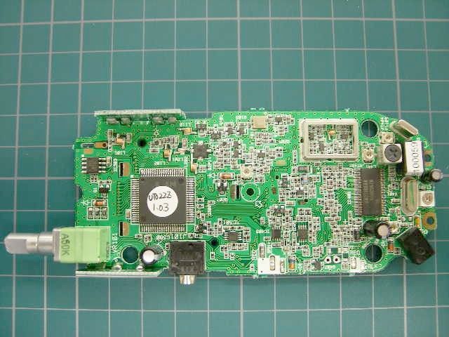
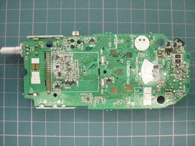
GENERAL INFORMATION General Information in accordance with the Federal Communications Commission Rules and Regulations, Volume II, Part 2. 1. Applicant: Uniden America Corporation Engineering Services Office 181 N. Country Club Road, P.O. Box 580 Lake City, South Carolina 29560 Mr. James R. Haynes, Vice president 2. Equipment Identification: FCC ID: AMWUT022 MODEL : 21-1936 3. Quantity: Quantity Production is planned. 4. Emission Type: 11K0F3E 5. Frequency Range: 462.5625 – 467.7125MHz (FRS) 462.5500 – 462.7250MHz (GMRS) 6. Operating Power (ERP): 0.30 W erp(FRS) 1.00 W erp(GMRS: Boost mode) 7. Max. Power Rating: According to the section 95.135 and 95.639 of the FCC Rules. 8. DC voltage and current into Final Amplifying Device: Refer to test data 9. Solid State Devices: Refer to Parts List/Tune-up Info 10. Circuit & Block Diagrams: Refer to EXHIBITS 11. Instruction Manual: Refer to User Manual 12. Tune-up Procedures: Refer to Parts List/Tune-up Info 13. Circuit Descriptions: Refer to Operational Description Means for Frequency Stabilization Means for Attenuation of Spurious Emissions Means for Limiting Modulation 14. Description of Digital Modulation Techniques: Not Applicable 15. Standard Test Conditions: The following conditions and procedures were followed during testing of the equipment. Room Temperature: 23 - 27 Degrees Celsius Room Humidity: 40 - 60 % Power Supply Voltage: 4.8V - NiMH Battery Pack -or- 6.0V - 4 AAA Alkaline Batteries Note: Prior to testing, the unit is tuned-up according to the manufacturer's alignment procedure. All presented data will represent the "worst case" parameter being measured. 16. Equipment Identification: A drawing of the equipment's Identification Label and, its location are as shown in ID Label/Location Info. 17. Photographs: External photographs of the unit as well as internal photos of the printed circuit boards are found in External Photos and Internal photographs.
Cover Letter(s)
REQUEST FOR CONFIDENTIALITY June 3, 2006 To: Federal Communications Commission Equipment Authorization Branch Laboratory Division Office of Engineering and Technology 7435 Oakland Mills Road Columbia, Maryland 21046 Subject: Data for FCC Certification under Part 95 Applicant: Uniden America Corporation 181 N. Country Club Road, P.O. Box 580 Lake City, South Carolina 29560 James R. Haynes, Vice President, Engineering and Regulatory Affairs TYPE OF EQUIPMENT: FRS/GMRS Hand Held Transmitter FCC IDENTIFIER: AMWUT022 Dear Sir or Madam: Some of the material included in this application contains trade secrets and proprietary information not customarily released to the public. Because public disclosure of the material might be harmful to the applicant and provide unjustified benefits to its competitors, it is requested that the following be withheld from public disclosure: Circuit Description Schematic Diagrams Block Diagrams Trade secrets and proprietary information can be held confidential. Therefore, we wish to invoke the act under the provisions of 47CFR, Sections 0.457(d) and 0.459. Please contact the undersigned if you have any questions or need any further information. Regards, James R. Haynes Vice President, Engineering and Regulatory Affairs
ID Label/Location Info
ID Label/Location Info Equipment Identification Label The FCC Label complies with the section 2.925(d) of the FCC Rules and will be permanently affixed to the equipment. Rating label: 32 mm (W) x 7.2 mm (H)
Parts List/Tune Up Info
FORM-4 REFERENCE DIAGRAM NO. PAGE MODEL UNIT BLOCKISSUE DATE ISSUED 2006/5/24SAKAIHI TITLE ADJUST POINT SUB TITLE REF DIAGRAM 1. MAIN PCB B101 (TOP VIEW)2. MAIN PCB B101 (BOTTOM VIEW) TP1 : VCONT+6V:DC 6VL182 : VCONT ADJ. TP2 : DISC OUT(De_Em )LOCAL OUTL401 : DISC.ADJ. TP3 : BALANCERF IN/OUTRT201 : TX POWER ADJ. TP4 : AF OUTUPCT401 : FREQ. ADJ. TP5 : MIC INDNRT402 : MOD. BALANCE ADJ TP6 : BOOSTCHG:DC 11VRT403 : MAX DEV. ADJ. TP7 : PTT with CHARGE JIGRT404 : SQ ADJ. TP8 : BATT SEL REV. CODE DATE LOT # / RN # REVISED BY CHECKED BY ENGLISH VERSION02.09 JQD818ZF011 R0 UT022ZH ALIGNMENT PROCEDURE CHG JACK ALIGNMENT PROCEDURE FORM - 3 PAGE MODEL UNIT BLOCKISSUE DATE ISSUED 2006/5/24 TITLETEST MODESUB TITLECONFIRMATION REF DIAGRAM TEST MODE REV. CODE DATE LOT # / RN # REVISED BY CHECKED BY ENGLISH VERSION02.09 JQD818ZF013 R0 UT022ZH SAKAIHI
RF Exposure Info
Company: Uniden America Corporation FCC ID: AMWUT022 462.5500 - 467.7125 MHz Model(s): 21-1936 DUT Type: Portable FM UHF FRS/GMRS PTT Radio Transceiver 2006 Celltech Labs Inc. This document is not to be reproduced in whole or in part without the prior written permission of Celltech Labs Inc. Page 1 of 39 Test Report Serial No.: 052306AMW -T752-S95U Report Issue Date: June 02, 2006 Date(s) of Evaluation: May 26, 2006 Report Revision No.: Revision 1.0 Description of Test(s): RF Exposure SAR FCC 47 CFR §2.1093 OET 65, Supplement C R R F F E E X X P P O O S S U U R R E E E E V V A A L L U U A A T T I I O O N N S S P P E E C C I I F F I I C C A A B B S S O O R R P P T T I I O O N N R R A A T T E E S S S A A A R R R T T T E E E S S S T T T R R R E E E P P P O O O R R R T T T FOR UNIDEN AMERICA CORPORATION PORTABLE UHF FRS/GMRS PTT RADIO TRANSCEIVER MODEL(S): 21-1936 FCC ID: AMWUT022 (FCC OET BULLETIN 65 SUPPLEMENT C) Test Report Serial Number 052306AMW-T752-S95U Test Report Revision Number Revision 1.0 (Initial Release) Test Lab Celltech Compliance Testing & Engineering Lab (Celltech Labs Inc.) 1955 Moss Court Kelowna, BC Canada V1Y 9L3 Test Report Prepared By: Cheri Frangiadakis Test Report Writer Celltech Labs Inc. Test Report Reviewed By: Jonathan Hughes General Manager Celltech Labs Inc. Company: Uniden America Corporation FCC ID: AMWUT022 462.5500 - 467.7125 MHz Model(s): 21-1936 DUT Type: Portable FM UHF FRS/GMRS PTT Radio Transceiver 2006 Celltech Labs Inc. This document is not to be reproduced in whole or in part without the prior written permission of Celltech Labs Inc. Page 2 of 39 Test Report Serial No.: 052306AMW -T752-S95U Report Issue Date: June 02, 2006 Date(s) of Evaluation: May 26, 2006 Report Revision No.: Revision 1.0 Description of Test(s): RF Exposure SAR FCC 47 CFR §2.1093 OET 65, Supplement C Celltech Labs Inc. declares under its sole responsibility that this wireless portable device has demonstrated compliance with the Specific Absorption Rate (SAR) RF exposure requirements specified in FCC 47 CFR §2.1093 and Health Canada’s Safety Code 6. The device was tested in accordance with the measurement standards and procedures specified in FCC OET Bulletin 65, Supplement C (Edition 01-01) and Industry Canada RSS-102 Issue 2 for the General Population / Uncontrolled Exposure environment. All measurements were performed in accordance with the SAR system manufacturer recommendations. I attest to the accuracy of data. All measurements were performed by me or were made under my supervision and are correct to the best of my knowledge and belief. I assume full responsibility for the completeness of these measurements and vouch for the qualifications of all persons taking them. This test report shall not be reproduced partially, or in full, without the prior written approval of Celltech Labs Inc. The results and statements contained in this report pertain only to the device(s) evaluated. DECLARATION OF COMPLIANCE SAR RF EXPOSURE EVALUATION Test Location CELLTECH LABS INC. Testing and Engineering Services 1955 Moss Court Kelowna, B.C. Canada V1Y 9L3 Phone: 250-448-7047 Fax: 250-448-7046 e-mail: [email protected] web site: www.celltechlabs.com Company Information UNIDEN AMERICA CORPORATION Engineering Services Office 181 N. Country Club Road Lake City, SC 29560 United States FCC IDENTIFIER: AMWUT022 Model(s): 21-1936 Test Requirement(s): FCC 47 CFR §2.1093; Health Canada Safety Code 6 Test Procedure(s): FCC OET Bulletin 65, Supplement C (Edition 01-01) Industry Canada RSS-102 Issue 2 Device Description: Portable UHF FRS/GMRS PTT Radio Transceiver Modulation Type: FM (UHF) Transmit Frequency Range(s): 462.5500 - 462.7250 MHz (GMRS Channels 15-22) 462.5625 - 462.7125 MHz (FRS/GMRS Channels 1-7) 467.5625 - 467.7125 MHz (FRS Channels 8-14) Max. RF Output Power Tested: 1.00 Watts (30.01 dBm) ERP (462.5625 MHz) GMRS Ch. 1 (Boost Mode) Power Mode(s) Tested: Boost Mode (for face-held operation with NIMH battery only) Normal Mode Antenna Type(s) Tested: Fixed External Battery Type(s) Tested: NiMH Battery Pack 4.8 V, 700 mAh (Model: BP38) Alkaline Duracell Procell AAA x4 (1.5 V, 1150 mAh) Body-Worn Accessories Tested: Plastic Belt-Clip (P/N: UT-018A) Audio Accessories Tested: Headset-Microphone with PTT (P/N: n/a) Max. SAR Level(s) Evaluated: Face-Held: 1.39 W/kg (1g) - 50% duty cycle Body-Worn: 0.900 W/kg (1g) - 50% duty cycle Test Report Approved By: Sean Johnston Compliance Technologist Celltech Labs Inc. Company: Uniden America Corporation FCC ID: AMWUT022 462.5500 - 467.7125 MHz Model(s): 21-1936 DUT Type: Portable FM UHF FRS/GMRS PTT Radio Transceiver 2006 Celltech Labs Inc. This document is not to be reproduced in whole or in part without the prior written permission of Celltech Labs Inc. Page 3 of 39 Test Report Serial No.: 052306AMW -T752-S95U Report Issue Date: June 02, 2006 Date(s) of Evaluation: May 26, 2006 Report Revision No.: Revision 1.0 Description of Test(s): RF Exposure SAR FCC 47 CFR §2.1093 OET 65, Supplement C TABLE OF CONTENTS 1.0 INTRODUCTION ___________________________________________________________________ 4 2.0 DESCRIPTION OF DEVICE UNDER TEST (DUT)_________________________________________ 4 3.0 SAR MEASUREMENT SYSTEM ______________________________________________________ 5 4.0 MEASUREMENT SUMMARY _________________________________________________________ 6 MEASUREMENT SUMMARY (CONT.) _____________________________________________________ 7 5.0 DETAILS OF SAR EVALUATION______________________________________________________ 8 6.0 EVALUATION PROCEDURES ________________________________________________________ 8 7.0 SYSTEM PERFORMANCE CHECK ____________________________________________________ 9 8.0 SIMULATED EQUIVALENT TISSUES _________________________________________________ 10 9.0 SAR SAFETY LIMITS ______________________________________________________________ 10 10.0 ROBOT SYSTEM SPECIFICATIONS _________________________________________________ 11 11.0 PROBE SPECIFICAT…
Text truncated - open the document above for the full version.
Test Report
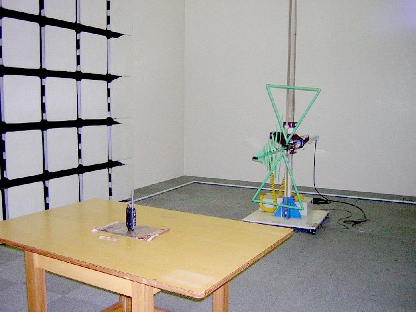
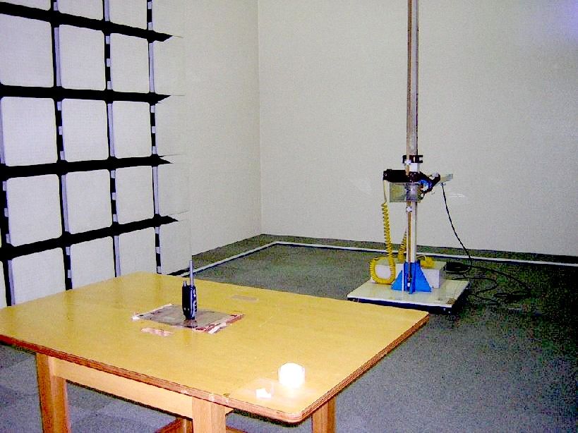
Test Report TEST PROCEDURES AND TEST SITE DESCRIPTION DATE: 5-31-06 FCC ID: AMWUT022 MODEL: 21-1936 DESCRIPTION: 22CH FRS/GMRS RADIO Tested by: Mr. Hiroyuki Sakai, Uniden Corporation MEASUREMENT ITEMS Section No. 1. DC Voltage & Current into Final Device 2.1033(C)(8) 2. RF Output Power 2.1046 3. Modulation Characteristics (Audio Roll-off) 2.1047 4. Modulation Characteristics (Audio Frequency Response) 2.1047 5. Modulation Characteristics (Modulation Limiting) 2.1047 & 95.637(a) 6. Occupied Bandwidth 2.1049(c)(1) & 95.635(b)(1)(3)(7) 7. Spurious & Harmonic Emission at Antenna Terminal 2.1051 8. Field Strength of Spurious/Harmonic Radiation 2.1053 & 95.635(b)(7) 9. Frequency Stability (Temperature) 2.1055 10. Frequency Stability (Voltage) 2.1055 NOTE: List of measurement equipment and test site description are included in this EXHIBIT. 1. DC Voltage & Current into Final Device 2.1033(C)(8) ------------------------------------------ To measure the DC Voltage and Current into Final Amplifying Device, the measuring equipment was connected to the actual P.C.Board of the transmitter. FCC limits: Not specified Test Results: Refer to test data 2. RF Output Power 2.1046 & 95.639 ------------------- The unit was tuned-up in accordance with the alignment procedure stated in the EXHIBIT-6, and was loaded into a 50-ohm resistive termination. The unit was powered through its normally supplied power cable by a DC power supply. Power supply voltage was set to nominal voltage at the power supply terminals with the transmitter off. The unit was operated for three consecutive test cycles of 15 minutes standby and 5 minutes in transmitting. At the end of the third 5 minutes period, the RF output power is measured. During the test, no components of the emission spectrum exceed the limit specified in the applicable rule part for occupied bandwidth or emission limitations. FCC limits: 0.5 W ERP for FRS and 5W ERP for GMRS Test Results: Refer to test data 3. Modulation Characteristics (Audio Roll-off) 2.1047 ----------------------------------------------- To measure the audio roll-off filter response, an audio frequency oscillator and AF VTVM were connected to the actual P.C.Board of the transmitter. AF VTVM and an oscilloscope monitored the output of the audio filter. An AF input level was maintained was maintained constant at least 10 dB below the saturation level at maximum response frequency. The measurement was made under the above conditions by varying the frequency between 1 kHz and 100 kHz. FCC limits: 3 kHz - 20 kHz: -60 log 10 (F/3) dB Test Results: Refer to test data 4. Modulation Characteristics (Audio Frequency Response) 2.1047 --------------------------------------------------------- The audio frequency response was measured in accordance with TIA/EIA Specification 603. Operate the unit under the standard test conditions and monitor the output with a modulation or a calibrated test receiver. The input required to produce 30 percent modulation level was measured. 5. Modulation Characteristics (Modulation Limiting) 2.1047 & 95.637(a) ---------------------------------------------------- The transmitter shall be adjusted for full rated system deviation, 1000 Hz and reference it as 0dB input. With modulation frequencies of 300, 1000 and 3000 Hz respectively, vary the audio input to a level 20dB above that required at 100 Hz to produce 60% of rated system deviation. This is required for both up to and down modulation. Record the percent of full system deviation obtained as a function of input level. FCC limits: +/-2.5 kHz deviation Test Results: Refer to test data 6. Occupied Bandwidth 2.1049(c)(1) & 95.635(b)(1)(3)(7) ---------------------- The spectrum of the modulated carrier was monitored by a panoramic method capable of 60dB amplitude range. The unit was modulated with a 2500 Hz audio signal at an input level 16dB above that required for 50% of maximum system deviation. In case the 100Hz of CTCSS tone or 100 bps of digital coded data modulation is indicated for this transmitter, a representative measurement data for this operation is also presented. Since the total deviation of the unit is designed as 4.7 kHz Div., the deviation of 2500Hz audio signal was set to 3.7 kHz Div., as the maximum deviation of tone or digital coded signal was continuously set to 1.0 kHz Div. At first, tone or digital signal was disabled and set the 2500 Hz audio signal to 1.85 kHz deviation (= 50% of 3.7 kHz deviation). Then, the input level of 2500Hz audio signal was increased by 16dB. In this condition, the tone or digital coded signal was then enabled and imposed with 2500Hz audio signal. FCC limits: a) -25dB (50 - 100% of assigned frequency) b) -35dB (100 - 250% of assigned frequency) c) 43 + 10log 10 (RF output power in Watts) dB or 80dB, whichever is lesser attenuation for more than 250% of assigned frequency Test Results: Refer to test data 7. Spurious & Harmonic Emission at Antenna Terminal 2.1051 ---------------------------------------------------- Spurious radiation are the radio frequency voltage or power generated within the equipment and appearing at the equipment's output terminals when properly loaded with its characteristic non-radiating load. The unit was modulated with a 2500 Hz tone at an input level 16dB greater than that required 50% modulation. The spectrum was scanned from the lowest frequency generated in the equipment to the tenth harmonic of the carrier. FCC limits: 43 + 10log 10 (RF output power in Watts) dB Test Results: Refer to test data . 8. Field Strength of Spurious & Harmonic Radiation 2.1053 --------------------------------------------------- Measurement Procedure & Test Site Description Field strength measurements of radiated spurious emissions were made on a 3-meter range maintained by Uniden Corporation in Japan. Complete description and measurement data of this test site have been placed on file with the Commission. The equipment was scanned for radiated emissions in a scheduled enclo…
Text truncated - open the document above for the full version.
Contact Information
Applicant
Paul Roby
Test Firm
Uniden CorporationKeizo Fujiwara
Technical Specifications
| # | Rule Parts | Frequency Range | Power Output | Emission | Tolerance |
|---|---|---|---|---|---|
| 2 | 95A | 462.55 MHz - 462.725 MHz | 1 W | 11K0F3E | 2.5 ppm |
Other Applications from Uniden America Corporation
AMWUA2405
Apr 15, 2026RADAR DETECTOR
Equipment Class
JBP - Part 15 Class B Computing Device PeripheralAMWUA2406
Apr 15, 2026RADAR DETECTOR
Equipment Class
JBP - Part 15 Class B Computing Device PeripheralAMWUA2402
Jul 23, 2024RADAR DETECTOR
Equipment Class
CRD - Part 15 Radar Detector
AMWUA2404
Feb 17, 2024Wi-Fi Bluetooth Combo Module
Equipment Class
DTS - Digital Transmission System
AMWUA2301
Feb 15, 2023RADAR DETECTOR
Equipment Class
CRD - Part 15 Radar Detector